Proceedings of the 2006 IEEE International Conference on Robotics and Automation Orlando, Florida - May 2006
Enhanced Real-Time Execution of Modular Control Software based on IEC 61499 Alois Zoitl, Rene Smodic and Christoph Sünder
Gunnar Grabmair
Automation and Control Institute Vienna University of Technology, Austria Email: {zoitl|smodic|suender}@acin.tuwien.ac.at
Upper Austria University of Applied Science Wels, Austria Email:
[email protected]
comparing the execution overhead introduced by adding additional execution threads in a Java-based environment. An event path concept with annotated real-time constraints has been introduced by [13]. This event path concept allows to derive a priority assignment scheme for function blocks (FB), which enables real-time execution of IEC 61499 applications if each FB of such an event path gets its own execution context. Reference [16] derived a simple real-time execution model for IEC 61499 where each real-time constraint resource could contain only one real-time constraint. Although this model is easy to implement and predictable, it's rather fixed and not flexible enough to serve the needs of application designers. The mapping from the event based IEC 61499 execution to a cyclic scan-based system as it is used in traditional PLC systems has been shown in [9]. This mapping allows a deterministic pre-verifiable execution behavior and response times for the application. But the main limiting point is the large overhead introduced by the scan cycle and as a result of this overhead the larger overall response time of the application. In this work we cover the behavior of IEC 64199 execution models within a single control device. First a short overview of the IEC 61499 elements provides the basics for our investigation. A representative application example—a motion control task—is used to derive requirements for an execution support system. We present different execution models and validate them to this application example. Based on this a novel approach to map exiting real-time execution theory to IEC 61499 execution models will be presented. An analysis shows that the new approach is more efficient than existing approaches and will also meet the requirements introduced by the application example.
Abstract – The ever increasing complexity of manufacturing systems demands for new real-time control infrastructures. With the new standard IEC 61499 the IEC introduced a base for such a control infrastructure. An open issue of this standard is the missing definition of real-time execution. Based on existing realtime execution theory different execution models for real-time execution of IEC 61499 control applications are analyzed in this work. A novel execution approach for an efficient execution model is presented. This new approach will serve as basis for a new IEC 61499 execution environment. Index Terms - IEC 61499, distributed control, real-time scheduling.
I. INTRODUCTION The complexity of manufacturing plants is ever increasing in order to serve the arising needs of the market. In addition an increasing demand for lower downtimes and higher productivity even amplifies the growing complexity. Reconfigurable Manufacturing Systems (RMS) [8] are a possible approach for higher flexibility and lower downtimes through an adaptive reconfiguration approach. The basic need for supporting RMSs is a modular real-time control infrastructure. State of the art Programmable Logic Control (PLC) technology is not capable and has not been designed for solving such challenges. With the new international standard IEC 61499 ([6]) the International Electrotechnical Commission (IEC) made first steps into a new direction. The architecture defined in this standard solves the basic problems of flexible distributed control systems. None the less there are open points in its definitions. These are the specification method and execution models for real-time constrained control applications and providing the necessary flexibility for reconfiguration of control applications in real-time. Deterministic real-time execution of IEC 61499 applications is the base for supporting the proposed services of RMSs [15]. Therefore this work focuses on the analysis of the execution behavior and a real-time execution support for IEC 61499. Up to now most work regarding execution of IEC 61499 deals only with parts of the standard elements and not directly with real-time execution. Reference [12] examines different event propagation strategies and their impact on the execution behavior of IEC 61499 applications in detail. Reference [4] compares different implementation strategies for IEC 61499 Function Blocks (FBs) regarding their execution behavior and
0-7803-9505-0/06/$20.00 ©2006 IEEE
II. EXECUTION BEHAVIOR OF IEC 61499 APPLICATIONS As a base for executing real-time constrained IEC 61499 applications this section investigates the basic structure of IEC 61499. The standard defines several models—application, system, device, resource, and the FB model—that allow the control engineer to develop distributed control applications in an intuitive and graphical manner. Hereby the main focus of this paper lays on the execution behavior of these models and their interaction. A full description of IEC 61499 may be found in the standard [6] or in a more readable form in the book [10].
327
B a sic S TART
C o m m u n ica tio n In te rfa ce
1 EX
1 IN I T
C o m m u n icatio n In ter fac e D e vice M an ag e m e n t y M an ag es A pp lica tion s y C o m m a nd s y y y y y y
c reate initia lis e s ta rt s to p delete que ry
R es o u rc e A
M A IN
I NI T
R es o u r ce B
R e so u rc e C
I N IT
M AIN
EXO
I N IT O
C om p os ite
A pp lica tion 1 A p plic atio n 2 A pp lic ation 3 P ro ce ss In ter fa ce
P ro ce ss In ter fa ce
S e rv ic e In te rfa ce
S ch ed u lin g fu n c tio n
a ) D ev ic e
application
b ) R e s ou rc e
resource
INIT(+) PARAMS
startService
INITO(+) STATUS
c ) F un ctio n B loc k T yp es
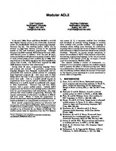
Fig. 1 Overview of the Executable Elements within an IEC 61499 Device
Our first attempt on analyzing the execution behavior of IEC 61499 considers only the elements within one controldevice. These are at first the device1 containing resources, and a device management. A resource contains applications or application parts built from interconnected FBs. The device management administrates the life cycle of the resources and their applications. Fig. 1 shows these elements and their interrelation.
If a device does not contain any resource explicitly it has to behave like a resource at large and has to allow the execution of IEC 61499 applications built from connected FBs. So the device needs a twofold functionality. C. Resources A resource is a functional unit that serves as containment for applications or application parts residing in the specific device and has independent control of its operation. Within a device resources can be created, deleted, configured, etc. without interfering with other resources and their applications. A resource has to support the device in its task to encapsulate the contained applications properly. For applications built as FBNs a resource has to provide an execution environment. That means it has to deliver event notifications to FBs and has to allow FBs to process the incoming events corresponding to their internal structure (see section II.C). The kind of delivering events has great influence on the behavior of the whole FBN and can lead to undesired side effects ([4] and [12]). A resource gets access to the communication interface services and process interface services from the device. Service Interface Function Blocks (SIFBs) are the means to provide these services to the applications.
A. Applications Applications are the main element of IEC 61499 for the user to model control functionality. They are modeled as Function Block Networks (FBNs) consisting of interconnected FBs with event- and data-connections (example shown in Fig. 1b). Applications are in general compiled without any device or control infrastructure in mind. Therefore IEC 61499 allows the mapping of applications to the devices they should be executed on after the modeling process. It is even possible to map parts of applications to different devices (not considered in this work) or to several resources within a device (e.g. Application 2 in Fig. 1). B. Devices A device is the IEC 61499 representation of any control equipment with the ability to hold IEC 61499 resources and to execute IEC 61499 applications. It consists of a communication interface, a process interface, the device management, and can contain zero or more resources. The communication interface provides communication services for the device and the application parts residing in this device. The process interface provides the services for accessing the sensors/actuators needed to control the process. In difference to the resources defined in the standard IEC 61131-3 [5] IEC 61499 not necessarily associates a resource to one own local computational unit (e. g. one CPU). Therefore a device has to take care that each resource gets computing time corresponding to the needs of the resource or the contained application. It also handles that the execution of the resource must not interfere with other resources.
D. Function Blocks A FB is the smallest functional unit used for modelling IEC 61499 applications. From the designers point of view mainly the interface and the functionality it provides is important. That means if an input event arrives some execution (e.g. processing input data, generating output data) is triggered, and corresponding output events are sent if necessary. How this execution is done internally in detail is unimportant in this context. IEC 61499 defines three main FB-types: Basic FBs remain passive until an input event arrives. The arrival of the event triggers the examination of the emerging transitions from the current active state in the Execution Control Chart (ECC). The first true transition activates a change to the next state. Entering a new state triggers the execution of actions. Actions are the execution of algorithms and/or the sending of output events.
1
Within this paper words written in italic are the names of the different IEC 61499 standard compliant model elements.
328
To execute algorithms the FB sends a request to the resource for scheduling the corresponding algorithm. The ECC remains passive until the algorithm finishes its execution. The scheduling-function of the resource (shown in Fig. 1b) has to schedule the algorithms correctly (see also Figure 6 in [6]). Composite FBs (CFBs) contain a FBN similar to a resource. Incoming events are passed on to the internal FBs. From the resource point of view there is no difference in executing a basic FB or a CFB. Internally the CFB behaves like a resource2, which handles the internal data and event connections. But it passes algorithm scheduling requests from inner basic FBs out to the resource like a normal basic FB. The difference for executing CFBs is only the overhead for passing on data and events. Service Interface FBs provide a mapping from device specific services to IEC 61499 FBs. In general there are two different types of SIFBs: the requester and the responder type. The requester type is an application initiated SIFB. That means it remains passive until an input event arrives. On such an arrival the SIFB utilizes the service it provides. Therefore the execution is similar to a basic FB. The responder type is a resource or hardware initiated FB. That means that the underlying service it provides can trigger its execution and the sending of output events. All events in a FBN can be seen as a result of such SIFBs, thus these SIFBs are the origin of all events. Therefore they are often called “event sources” (ES). Examples for frequently used event sources are the E_RESTART SIFB and the E_CYCLE SIFB as defined within the standard. As the underlying service can theoretically trigger the responder SIFB at any time and indefinitely often these SIFBs can disturb the execution of all FBNs in the device, because each trigger request needs processing time for execution. This can lead to undesired blocking of applications caused by overload of the processing unit and therefore the execution model has to treat this kind of SIFBs specially. The mapping between the services and the SIFBs is beyond the scope of the standard and therefore implementation specific.
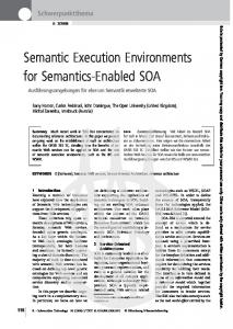
III. CONTROL APPLICATION EXAMPLE In this section a control example of real relevance—as already done in one of our experiments—is presented. This example serves as basis for the investigation on IEC 61499 application execution and its needs regarding real-time execution support. A common task in automation systems is motion control. Therefore a position control of a linear axis will serve as a basic example. Fig. 2 shows the block diagram of our control model. It is a feedback control consisting of two cascaded control loops. The inner loop ensures the velocity control of the axis and is directly interacting with the actuator of the axis. The outer loop is the position control. This loop delivers setpoints for the velocity control to reach the desired position. The user or some higher level control provides the setpoint for the position. This is not of direct interest for this example. Transforming this continuous control model to an IEC 61499 application we get a discrete closed loop control. For the two control loops a cyclic invocation of the controllers is necessary. In order to get reasonable control performance the sample rate of the velocity control should be 1ms. The sample rate of the outer control loop must be larger. 10ms have been chosen for this example. Fig. 3 shows the example transformed to an IEC 61499 application. The upper line of function blocks represents the velocity control loop. The first FB triggers the whole loop continuously every millisecond to execute. The execution sequence is as follows: first read the current value of the velocity, second calculate the control law (in this case a PIcontroller), and third write the output with the set value for the actuator of the axis. The position control loop is rather similar by first reading the current position of the axis used as input for the control law. The calculated control value is the setpoint input of the velocity control. The set-point of the position control loop is delivered from an external application via the network. In addition a simple monitoring block acquires the current values of the axis position and velocity and provides them for some Human Machine Interface (HMI). This IEC 61499 modeled application will be placed within one resource of an IEC 61499 compliant device. In order to achieve a good quality of control and a stable system the two control loops have to be executed every cycle period. For the following investigation let us assume that the control algorithms should deliver their output values without
E. Device Management The management functionality within a device has the main task to administrate all applications and the resources located in this device. It is also the functional unit that performs external reconfiguration requests. Within a device it provides the services that allow to create, initialize, start, stop and delete the instances and to query the attributes of resources. Within a resource the same services allow the handling of FB instances and their connections. When executing IEC 61499 applications within a device or a resource these management services have great influence on the execution behavior of the applications. They allow the changeability of the application while the application itself or other applications are executing. There should be no impact on the running applications.
P o sitio n C o n tro lle r
V e lo city C o n tro lle r vsp
P o s sp
-
A x is
vcu r
Fig. 2 Control Model of the Example Application 2
IEC 61499-1 does not consider nested resources but they could be a helpful extension to it.
329
P os cur
C y cle_ V elo city_ C o n tro l S T AR T STOP
EO
C u rren t_V elo city
R T _E _C Y C L E T #1 m s
V elo city_C o ntro ller
C NF
REQ
REQ
EC 3 S IF B _ IN
DT
CNF
S ET _S P
S e t_ M o to r_C urre nt REQ
PI PV
D O UT
CNF
S IF B _O U T D O UT
D IN
SP
P o sitio n
M o n ito rin g REQ1 REQ2
IN D
C ycle_P o sitio n_ C o n tro l
S U B S C R IB E R POS
S T AR T STOP
EO
DT
REQ
P os itio n _C on trolle r
C NF
R EQ
CNF
SE T _S P
R T _E _C Y C L E T# 10m s
C u rren t_P o sitio n
S IF B _ IN D O UT
HM I S P EE D
EC2
P O S IT IO N
PI DOUT
PV SP
EC1
R ea l-T im e E v en ts N orm a l E ve nts D ata C o nne ctio ns
E C 1 … E v e nt C hain 1 E C 2 … E v e nt C hain 2 E C 3 … E v e nt C hain 3
Fig. 3 Sample Motion Control Application for the Verification of our Concepts 3
delay . Therefore an execution environment has to assure the timely execution of the two control loops. In addition we have the position setpoint FBN that delivers data from outside of the resource to the position control loop. As the arrival time of this data cannot be foreseen the execution of this FBN must not interfere with the execution of the two control loops. The other application part that is less important than the control loops is the data acquisition for the HMI. For the HMI it is not necessary to acquire the data each cycle. Summarizing the application we have two cyclic real-time constrained application parts—the two control loops—and two non real-time constrained application parts, which exchange data and send events between each other.
In order to allow determinism a minimal interference is a prerequisite. Real-time scheduling theory provides means to schedule and execute such tasks and fulfill their timing constraints. In the following a comparison of different possibilities for applying the real-time task concept to the IEC 61499 models is presented. IEC 61499 defines that a resource serves as an independent execution context for the contained applications and application parts5. Therefore the resource comes into mind as the first IEC 61499 modeling element a task could be assigned to. This allows the parallel execution of applications in different resources without major interference. Within the resource the executing task has to provide facilities for delivering sent events and to execute FBs for a correct execution of FBNs. Taking our example from Fig. 3 the different application parts are executed within one task. Therefore the resource has to assure that the two real-time constrained application parts will meet their constraints. In addition means are necessary that the non real-time application parts will not interfere the execution of the real-time application parts. To achieve this requirement additional execution support like sub-tasks or special FBN scheduling and execution mechanisms are necessary. Therefore the direct mapping between real-time tasks and resources is not satisfying. Based on this concept in [16] a simple approach with only one ES per resource showed that such an approach is much too simple and restricts the control engineer in modeling his applications. Therefore alternative task definitions or additional execution means are necessary. Additional tasks are introduced if each FB has assigned its own execution task. This allows that all FBs execute their internal structure and elements independently. To transmit events between FBs inter-task communication methods are utilized. This approach of task assignment results in a larger amount of tasks (depending on the application size). The drawback is that real-time operating systems often provide only a limited number of real-time tasks for each application. Also many tasks are highly coupled because of event- and data-connections. This results in complicated synchronization structures, with non trivial or even unsolvable real-time scheduling problems. Reference [4] compares several different implementations for execution environments where each FB has
IV. EXECUTING REAL-TIME CONSTRAINT IEC 61499 MODELS Up to now IEC 61499 does not provide definitions for modeling and executing real-time constrained applications. By applying existing real-time scheduling and execution theory to IEC 61499 and investigating the execution necessities for IEC 61499 modeled control applications a full featured IEC 61499 execution environment with real-time support can be developed. A. First thoughts about mapping Real-Time Scheduling Theory Concepts to IEC 61499 In the field of real-time execution of control programs lots of research has been done during the last 30 years starting with the seminal work from C.L. Liu and J.W. Layland [11]. The main target was the field of scheduling theory and how to get predictable and deterministic execution behavior. To leverage the results of this research a mapping between IEC 61499 execution models and the models of the real-time scheduling theory is necessary. In terms of real-time scheduling the main element is a task, which [2] defines as follows: “A task is a sequential execution of code that does not suspend itself.” Tasks are considered independent in their execution and executed quasi paral4 lel. Tasks can have assigned real-time constraints . In general the activation of tasks can be periodic, aperiodic or sporadic. 3
In difference to write the output at the beginning of the next cycle (so called one unit delay). 4 E.g. deadline, release time, period, etc. for more information see in [3]
5
330
It is assumed that a device contains at least one resource.
-
Different ECs can trigger the same FB (e.g. EC1 and EC2 trigger the Position_Controller FB) - ECs can split and execute parallel branches (e.g. execution of the Monitoring FB in EC2 and EC3) - ECs with real-time constraints can have branches that are not real-time constrained (e.g. execution of the Monitoring FB in EC2 and EC3). - The length of the EC can vary depending on internal state and input data of the triggered FBs These aspects provide requirements to the execution environment and will be discussed in the following. The fact that ECs can have real-time constraints supports the approach that each constrained EC will get its own real-time execution task. Also from the modeling point of view this makes sense because control engineers are used to specify real-time constraints to the application parts in end to end form and not for each function (in our case a FB) as presented in [13]. This allows applying the well developed theories of the real-time scheduling community and the support of existing real-time operating systems for executing and scheduling control applications modeled in IEC 61499. The case that a FB can be triggered from different ECs is an important factor for the execution environment. Therefore a FB is part of different ECs and will be executed within the execution context of these ECs. This means that depending on the EC the FB currently participates the FB will inherit the execution properties (e.g. real-time constraints) from the triggering EC. For this behavior we introduce the term “Dynamic Task Membership”. Therefore a non ES-FB behaves in this case similar to a library function of a usual programming language. The execution environment has to provide means that the FBs are “reentrant” and their data and states are consistent while the FBs are executed. The typical way is to block other tasks when the FB is accessed by one task. Blocking the realtime execution of tasks is normally a bad idea, because it can cause that real-time constraints will not be met. Execution environments have to take this into account by special algorithms ([2]) or—if possible—through pre-analyzing the application and scheduling the tasks in a way that they will not interfere. Not supporting the “reentrance” of FBs results in extensive limitations for the control engineer and is therefore not favored for an implementation of an execution environment. A rather common element within an EC is the splitting in two or more branches. From the control engineers point of view the wish is that the different branches are executed in parallel. Apart from our definition of an EC this would sound like a logical starting point for new ECs. From the real-time execution point of view this would only be necessary if the constraints of the different branches are not the same. If for example all branches have the same deadline the goal is to finish the execution of all branches before the deadline. Executing branch after branch and finishing all branches before the deadline will result in the same quality of service as if the branches will be executed in own tasks, each task fulfilling its deadline. The only difference is, that the second implementation needs more system resources and results in more taskhandling overhead. If the branches stay as part of the originat-
assigned its own task. The measures showed that the overhead for synchronizing the different tasks resulted in a poorer execution performance of the application. Mainly it results in a higher worst case execution time, which is the determining factor for meeting real-time constraints. B. Using Event Sources for Task Assignment From a general point of view an IEC 61499 FB is a passive element. It only needs execution time when it is triggered by an arriving input event. This is an additional point why assigning each FB an own execution context is not appropriate. In an IEC 61499 application the only active elements are responder-FBs. While analyzing the execution flow of FBs and event notifications it can be observed that all execution paths origin from ES-FBs. Therefore assigning each ES-FB an own task allowing the execution of the outgoing events and connected FBs seems an appropriate way. With this concept a minor amount of real-time tasks is necessary. In the following we investigate the execution started from an ES-FB and its impact on an execution environment in more detail. C. Event Sinks Up to now we only spoke about the origins of events. But for a full execution behavior analysis of IEC 61499 applications also the sinks of events have to be considered. As an Event-Sink (ESK) we define the point in a FBN where the execution of a FB will not lead to any further FB-execution. There are three possibilities for the existence of such points. The simplest one is that the ESK is represented by a FB with no output events. This is not a very common FB because most FBs provide at least status outputs on the success of their execution. A more common point is that the output events are not connected to further FBs and therefore obviously no further execution will be initiated although an output event is sent. In that case it has been the decision of the application engineer to end the FB execution at this FB. The not so obvious to see ESK is the possibility that the internals of a FB decide not to send an output event. So although there are FBs connected to the ESK-FB output event there will be no further execution. D. The Event-Chain Concept With the ES and the ESK in hand we define an EventChain (EC) as the chain of FB executions started through an event occurrence at one ES-FB and ending in or more ESKs. This EC concept will serve as model and execution element in our further investigations. When applying this EC concept to our example from Fig. 3 three ES-FBs and therefore 3 ECs can be identified. EC1 starts at the Position FB and ends at the Position_Controller FB as the SET_SP event input will not execute the control law of the PI-FB. EC2 is the position control loop starting at the Cycle_Position_Control FB and ending at the Velocity_Controller and Monitoring FB. EC3 is the velocity control loop starting at the Cycle_Velocity_Control FB and ending at the Set_Motor and Monitoring FB. These three ECs show the main execution aspects and constraints that have to be taken into account: - ECs can have real-time constraints (e.g. deadline)
331
ing EC no special means are needed when the branches are joined again. Therefore we propose that branching within an EC will be part of the initiating EC. If for special cases a different behavior is needed the application engineer is advised to explicitly model the needed behavior with additional FBs. The E_SPLIT and E_MERGE FBs as defined in IEC 61499 can serve as a starting point for developing such FBs. If an outgoing event within a real-time constrained EC triggers the execution of non real-time constrained application parts the execution of the real-time constrained EC must not be interfered. An execution environment can start a new EC in such a case or pass the event trigger request on to a background task, which is assigned to the non real-time constrained resource execution handling. To guarantee real-time execution the determination of execution time of ECs is of great interest. The most important thing is to determine the longest lasting execution path within the EC in order to determine the Worst Case Execution Time (WCET). Only with this WCET it is possible to calculate deterministically if real-time constraints will be met. If the effective execution time will be shorter the constraints will still be met.
project under the FIT-IT contract FFG~808205. Further information is available at: www.microns.org REFERENCES [1] F. Barlarin, L. Lavagno, P. Murthy and A. Sangiovanni-Vincentelli, “Scheduling for Embedded Real-Time Systems”, IEEE Design & Test of Computers, vol. 15, no. 1, Jan.-March, 1998. pp. 71 - 82 [2] G.C. Buttazzo, “Hard Real-Time Computing Systems; Predictable Scheduling Algorithms and Applications”, Kluwer Academic Publishers, 1997 [3] C. Ekelin, J. Jonsson, “Real-Time System Constraints: Where do They Come From and Where do They Go?”, In Proceedings of the Int'l Workshop on Real-Time Constraints, Alexandria, USA, 1999, pp. 53-57. [4] L. Ferrarini and C. Veber, “Implementation approaches for the execution model of IEC 61499 applications”, INDIN04, in Proceedings of the IEEE Intern. Conf. on Industrial Informatics, Berlin, Germany, 2004, pp. 612 617. [5] IEC TC65/WG6, “IEC 61131-3: Programmable controllers – Part 3: Programming languages”, Geneva, 1993 [6] IEC TC65/WG6, “IEC 61499-1: Function Block – Part 1 Architecture”, Geneva, 2005 [7] H. Kopetz, “Real-Time Systems: Design Principles for Distributed Embedded Applications”, Kluwer Academic Publisher, Boston/ Dordrecht/ London, 1997 [8] Y. Koren, U. Heisel, F. Jovane, T. Moriwaki, G. Pritshow, G.Ulsoy and H. van Brussel, “Reconfigurable Manufacturing Systems”, in Annals of the International Institution for Production Engineering Research (CIRP), Vol. 48/2, 199, pp.527-539 [9] J. L. Martinez Lastra, L. Godinho, A. Lobov, R. Tuokko, “An IEC 61499 Application generator for Scan-Based Industrial Controllers”, 3rd International IEEE Conference on Industrial Informatics INDIN05, Perth, 2005 [10]R. Lewis, “Modeling Control Systems Using IEC61499 – Applying Function Blocks to Distributed Systems”, The Institution of Electrical Engineers, London, 2001 [11]C.L. Liu and J.W. Layland, “Scheduling Algorithms for Multiprogramming in a Hard-Real-time Environment”, Journal of the Association for Computing Machinery, vol. 20, no. 1, January, 1973, pp. 46 - 61. [12]W. Rumpl, C. Dutzler A. Zoitl and F. Auinger, “Platforms for scaleable Flexible Automation considering concepts of IEC 61499”, 5th IEEE/IFIP International Conference on Information Technology for Balanced Automation Systems in Manufacturing and Services, Cancun, Mexico, 2002 [13]G.S. Doukas, K. Thramboulidis: “A Real-Time Linux Execution Environment for Function Block Based Distributed Control Applications”, in Proceedings of the 3rd IEEE International Conference on Industrial Informatics, Perth, 2005 [14]V.V. Vyatkin, J.H. Christensen, J.L. Martinez Lastra and F. Auinger, “OONEIDA: An Open, Object-Oriented kNowledge Economy for Intelligent Distributed Automation”, in Proceedings of the 1st IEEE International Conference on Industrial Informatics INDIN'03, Banff, Canada, 2003. [15]A. Zoitl, F. Auinger, V.V. Vyatkin and J.L. Martinez Lastra, “Towards basic real-time reconfiguration services for next generation zerodowntime Automation systems”, International IMS Forum 2004, Global Challenges in Manufacturing, Cernobbio, Italy, 2004 [16]A. Zoitl, G. Grabmair, F. Auinger and C. Sünder, “Executing real-time constrained Control Applications modeled in IEC 61499 with respect to Dynamic Reconfiguration”, 3rd International IEEE Conference on Industrial Informatics INDIN05, Perth, 2005
V. CONCLUSION AND OUTLOOK We did a deep investigation on the execution of IEC 61499 models within a control device. Starting with the definitions of the standard we introduced a representative example providing the requirements for an execution environment supporting real-time execution. Based on this example a mapping between IEC 61499 and existing research in the area of real-time scheduling and execution has been done. By deriving the new Event-Chain Concept a method for optimal— most flexible—assignment of real-time execution tasks to IEC 61499 execution models has been developed. For further work on this topic the EC-Concept will serve as basis for not only an execution environment but also for real-time application modeling methodology. To validate this work the direct next step will be to implement the presented concept and test it with the presented application example and with other representative applications from the domain of industrial automation and control. When the basic execution environment has proven its functionality it will be enhanced with reconfiguration functionality to allow the adoption of control application at run-time. ACKNOWLEDGEMENT This work is supported by the FIT-IT Embedded Systems program, an initiative of the Austrian federal ministry of transport, innovation, and technology (bm:vit) within the μCrons-
332