This article has been accepted for publication in a future issue of this journal, but has not been fully edited. Content may change prior to final publication. Citation information: DOI 10.1109/ACCESS.2018.2802948, IEEE Access
Date of publication xxxx 00, 0000, date of current version xxxx 00, 0000. Digital Object Identifier 10.1109/ACCESS.2017.Doi Number
Enhancement of Data Rate and Packet Size in Image Sensor Communications by Employing Constant Power 4-PAM Duy Thong Nguyen, Yoonsung Chae, and Youngil Park Department of Electronic Engineering, Kookmin University, Seoul 02707, South Korea
Corresponding author: Youngil Park (e-mail:
[email protected]).
This work was supported by Basic Science Research Program through National Research Foundation of Korea(NRF) funded by the Ministry of Education (NRF-2015R1D1A1A01059416).
ABSTRACT Image Sensor Communications (ISC) is a scheme to make the LED lamp replace access points (AP) or beacons in indoor environments. Its application has been limited, however, due to its low data rate and small packet size. To resolve these problems, we propose a new ISC scheme using 4-PAM modulation and a parallel packet structure. The constant power 4-PAM signal was designed to have constant optical power in each symbol to eliminate the flickering effect. The experiments show that a data rate more than 2.6 times higher than the existing On-Off Keying (OOK) schemes was achieved. In addition, it is demonstrated that the packet length can reach more than several frames while it is limited to less than a frame using the existing schemes. The limiting factors of N-PAM levels and packet size are analyzed in this paper to further improvement. All these results are demonstrated through simulations and experiments. INDEX TERMS Image sensor communication, Constant-power PAM, inter-frame gap, long packet.
I. INTRODUCTION
In recent years, visible light communication (VLC) has emerged as a new method of high-speed transmission in the indoor environments. VLC uses LEDs to transmit signals and a photodiode (PD) to receive signals [1]. It has more advantages than traditional Radio Frequency (RF) technology, which has become overloaded. An LED can be easily integrated into any lighting system. Moreover, compared to incandescent or fluorescent lamps, it has many advantages, such as multiple colors, compactness, long life, lower power consumption, higher energy conversion efficiency, and no effect on human health. In addition, traditional RF technology has limited usability in electromagnetically sensitive areas such as airports, hospitals, and places where RF cannot reach, such as tunnels, basements, or mines. Image Sensor Communication (ISC) is also part of VLC and uses a camera as a receiver [2]. Integrating cameras and image sensors into mobile devices has become popular in modern life. The quality of Image Sensors (IS) is improving. However, data rate is a problem that ISC systems need to improve further. A camera with a high resolution, frame rate or short exposure time can improve data rates.
VOLUME XX, 2017
However, these parameters are limited by hardware. Therefore, in this paper, we present two schemes to improve data rates; optimizing the header of the packet, and an efficient modulation. Flickering occurs when multiple consecutive bits are transmitted over a long period and can be overcome by using modulation schemes such as Manchester, 4B6B and 8B10B [3], which reduce the data rate of the ISC system. However, these schemes cause many waste bits, and the data rate is seriously decreased. Another cause is the Interframe gap (IFG) [4]. There is a ‘free’ interval between two consecutive frames; during this period, the camera does not expose, and as a result, a signal transmitted during that time is not received by the camera. Therefore, packets must be sent several times to ensure that at least one of them are received [5–6]. The system in [4] must insert error correction code to compensate for the lost bits in the IFG, or a dual camera is used to overcome the IFG [7]. Therefore, in this paper, we applied PAM to the ISC system. Since each symbol can carry multiple bits of information at the same time, this is believed to improve the data rate. However, a prototype PAM cannot eliminate flickering, and therefore, Constant Power (CP) PAM modulation is proposed. According to the structure of the packets
2169-3536 © 2017 IEEE. Translations and content mining are permitted for academic research only. Personal use is also permitted, but republication/redistribution requires IEEE permission. See http://www.ieee.org/publications_standards/publications/rights/index.html for more information.
1
2169-3536 (c) 2018 IEEE. Translations and content mining are permitted for academic research only. Personal use is also permitted, but republication/redistribution requires IEEE permission. See http://www.ieee.org/publications_standards/publications/rights/index.html for more information.
This article has been accepted for publication in a future issue of this journal, but has not been fully edited. Content may change prior to final publication. Citation information: DOI 10.1109/ACCESS.2018.2802948, IEEE Access D. T. Nguyen, Y. S. Chae and Y. I. Park: Enhancement of Data Rate and Packet Size of ISC by Employing CP 4-PAM
proposed in [4–7], the packet length is limited by a frame, and thus the data rate is limited. In this paper, we propose two types of packets for this scheme. Since a packet is longer than one frame, the length is suitable for an Ethernet packet, and it is easy to integrate any robust error correction code. II. PHYSICAL PROBLEMS OF N-PAM IN ISC SYSTEM AND PROPOSED SOLUTIONS
attributed to the nonlinearity of both the LED and the MOSFET transistor in the driving circuit. Therefore, the driving circuit is designed to achieve light intensity in the LED output with a uniform interval. Assuming that I is the highest light intensity of N-PAM, each level is generated as in (1). I1 0, I 2
I k 1 ,..., I k I ,..., I N I ,1 k N ( N 1) N 1
(1)
Since the image sensors installed in current camera systems are designed for image capturing, not for data transmission, there are several limiting factors that hinder high-speed transmission. Although N-PAM is a bandwidth-efficient modulation scheme, the parameters of image sensors should be adjusted carefully to avoid effects such as flickering and saturation. A. THE FLICKERING PROBLEM AND PROPOSED CONSTANT-POWER (CP) 4-PAM
Flickering is one of the factors that affect data rates in ISC systems and should be considered when combining communication with illumination systems. While light flickering normally occurs as the result of voltage ripple at the supply's output, the causes of flickering in ISC systems are light modulation, modulation frequency, ambient light conditions, the sensitivity of the human eye, and other similar phenomenon. In this paper, a PAM modulation is investigated to enhance the data rate. The input data is encoded to PAM levels and used to control the brightness of the light source (i.e., LED optical power). Obviously, the original PAM cannot be used in the ISC system since flickering occurs when symbols with the same amplitude level are transmitted over multiple bit periods, as seen in Fig. 1(a). An ISC scheme using PAM is studied in [8], but the flickering problem was not considered. Therefore, we suggest the insertion of a ‘compensation part’ after the signal part in each bit period, as shown in Fig. 1(b). This would help avoid flickering since it makes the average optical power the same in each bit, as found in the Manchester coding in binary OOK modulation. We call this a CP PAM. An example of CP 4-PAM is shown in Table I. 4-PAM Data
TABLE I LEVELS OF CONSTANT POWER 4-PAM Constant Power 4-PAM 4-PAM Level Main level Compensation level
11
3
3
0
10
2
2
1
01
1
1
2
00
0
0
3
In addition, PAM levels with uniform intervals are required to reduce flickering and decode the data accurately, as indicated in Fig. 2. However, the light intensity of the LED is not linearly proportional to the input voltage
2
Fig. 1. The elimination of flickering in the proposed CP 4-PAM. (a) The principle of 4-PAM. (b) CP 4-PAM.
The data rate efficiency of CP 4-PAM is reduced by half due to the compensation part, which may, however, be used for error detection. The bandwidth efficiencies of the VLC modulation schemes [4–7] are compared in Table II, which shows that CP N-PAM is an effective choice. Flickering has almost been eliminated by CP PAM. However, to evaluate the degree of flickering, we compared it with existing OOK coding at the same frequency. Percent flicker and flicker index are the parameters commonly used to evaluate flickering. Percent flicker is calculated based on the intensity of the light source while the flicker index has the advantage of being able to account for differences in the waveform shape, as shown in Fig. 2. Percent flicker and flicker index are calculated as in (2) and (3) [9]. max _ value min _ value (2) Percent flicker 100. max _ value min _ value area1 Flicker index (3) area1 area 2
Fig. 2. A single period waveform is used in the calculation of flicker metrics.
VOLUME XX, 2017
2169-3536 (c) 2018 IEEE. Translations and content mining are permitted for academic research only. Personal use is also permitted, but republication/redistribution requires IEEE permission. See http://www.ieee.org/publications_standards/publications/rights/index.html for more information.
This article has been accepted for publication in a future issue of this journal, but has not been fully edited. Content may change prior to final publication. Citation information: DOI 10.1109/ACCESS.2018.2802948, IEEE Access D. T. Nguyen, Y. S. Chae and Y. I. Park: Enhancement of Data Rate and Packet Size of ISC by Employing CP 4-PAM
Manchester 50
(%)
TABLE II COMPARISON OF BANDWIDTH EFFICIENCY() AMONG VLC CODING SCHEMES 4B6B 8B10B 4-PAM CP 4-PAM 67 80 200 100
According to the amplitude of the CP 4-PAM signal in Fig. 2 and the uniform levels generated in (1), the percent flicker value of CP-PAM is equal to the percent flicker value of the OOK modulation. Instead of frequency, the flicker index is a simple calculation based on the intensity as well as the shape of the waveform. According to Table I and Fig. 2, two shapes of the pulse are generated when level 1-2 and level 0-3 are transmitted. Level 1-2 corresponds to the lower value of flicker index as shown in Fig. 2. A higher flicker index value is obtained when level 0-3 is sent. This value is equal to the flicker index value in the schemes using OOK coding, which uses only two ON-OFF levels corresponding to the two levels of 3-0 in the scheme that are using CP 4-PAM. Obviously, the value of the flicker index of CP PAM scheme is always less than or equal to the schemes using OOK coding. Therefore, when evaluating flickering without considering the frequency, the CP 4-PAM scheme mitigates flickering compared to the existing schemes using OOK coding. In addition, a higher frequency will significantly reduce the flickering in the illumination system. Moreover, according to (2) and (3), a higher offset value will reduce the flicker metrics. This explains why flickering is easily noticed in low light environments. The higher offset value can be adjusted by increasing the transmitter power, but this is not energy efficient. Simultaneously, the space between the levels will be narrowed and cause saturation issues, so it is difficult to determine the thresholds and decode. B. THE SATURATION PROBLEM AND SHUTTER SPEED ADJUSTMENT
There are many parameters that affect the performance of ISC systems, such as shutter speed, lens size, and ISO value. To enhance the ISC performance, we need to receive as much light as possible, but there must be a linear relationship between input light and image sensor output since too much light degrades the uniform level intervals of PAM signals.
CP N-PAM log 2 ( N ) / 2
Es
Es
Fig. 4. The saturation of the image sensor in different environments. (a) Shutter speed=0.015 s, d=40 cm. (b) Shutter speed=0.045 s, d=40 cm. (c) Shutter speed=0.045 s, d=90 cm.
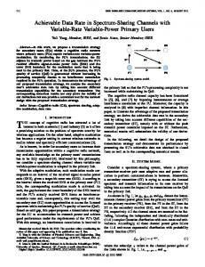
Although the lens size and ISO value can control the input light, the former cannot be changed during transmission and the latter may cause noise. Therefore, we must use shutter speed to change the amount of input light, and the effects of shutter speed are considered. In an ISC system with rolling shutter of CMOS sensors, the pulse shape of the received signal is estimated by the pixel values, which are then affected by the shutter speed. The amplitude and width of the pulse change with the shutter speed are shown in Fig. 3, where a slow shutter speed admits more light, increasing the amplitude and the width of the signal. In this figure, Es indicates the saturated pixel value. Therefore, the slow shutter can distort PAM signals, although it is helpful to achieve a better signal-tonoise ratio (SNR). Es
120
Es 100
80
60
40
20 Shutter Speed = 0.015 Shutter Speed = 0.045
0
0
10
20
30
40
50
60
70
Number of Pixel Rows
Fig. 3. The elimination of flickering in the proposed CP 4-PAM. (a) The principle of 4-PAM. (b) CP 4-PAM. VOLUME XX, 2017
Fig. 5. The relationship between light intensity, shutter speed, and image sensor output.
3
2169-3536 (c) 2018 IEEE. Translations and content mining are permitted for academic research only. Personal use is also permitted, but republication/redistribution requires IEEE permission. See http://www.ieee.org/publications_standards/publications/rights/index.html for more information.
This article has been accepted for publication in a future issue of this journal, but has not been fully edited. Content may change prior to final publication. Citation information: DOI 10.1109/ACCESS.2018.2802948, IEEE Access D. T. Nguyen, Y. S. Chae and Y. I. Park: Enhancement of Data Rate and Packet Size of ISC by Employing CP 4-PAM
Fig. 6. A block diagram of the proposed 4-PAM ISC scheme.
To investigate the effect of the shutter on the PAM signal, light intensity is measured with different shutter speeds and transmission distances, as shown in Fig. 4. When the shutter is fast enough, the four levels are sufficiently separate, even at the short distance in Fig. 4(a). However, for the slow shutter at the same distance in Fig. 4(b), the 4th level is saturated, and it is hard to differentiate it from the 3rd level, which will degrade the performance critically. As the distance becomes longer, the intensity at the side pixels becomes lower due to non-uniform brightness on the image sensor. Level saturation is observed at the center while it is eased at the side. From this experiment, it is found that the shutter speed should be small enough to avoid the level saturation problem using the N-PAM scheme. Saturation of the image sensor is dependent not only on the shutter speed but also on the amplitude of the modulation signal. A measured IS output as a function of shutter and modulation signal is shown in Fig. 5. As the modulation signal becomes larger, the pixels are found to be saturated at a faster shutter speed. In addition, a high amplitude of the output can be achieved even with a low optical power LED by adjusting the shutter speed, saving energy and enhancing the transmission performance. Therefore, it is required that the N-PAM levels should be measured periodically, and the most appropriate shutter speed should be selected according to the result. One of the advantages of the rolling shutter mechanism is a high data rate [4–7], but there are limitations. Unlike a VLC system using photo detectors, the image sensor is affected more by the rolling shutter mechanism since the amount of light reaching the image sensor depends on the speed of the shutter and its working mechanism. In practice, pixels in the center of image sensor often receive more light than the pixels at the edge of image sensor. Therefore, it is difficult to determine the threshold of each level. This phenomenon is called the ‘blooming effect’. To solve this issue in N-PAM, a polynomial regression is applied to determine its threshold. III. PROPOSED PACKET STRUCTURES AND CODING/DECODING PROCEDURES 4
Like other VLC systems, OOK coding is often used in ISC systems. In this case, redundant bits are inserted to avoid flickering by maintaining the brightness, which reduces the code’s efficiency. Therefore, in this paper, a scheme using CP 4-PAM has been proposed to improve the reduced data rate of the ISC system. The architecture of the proposed scheme is shown in Fig. 6. At the transmitter, the information bits are changed into corresponding 4-PAM levels and then converted to CP 4-PAM symbols according to the mapping process in Table I. This signal is used to drive the LED bulb. At the receiver, a CMOS image sensor is used to receive the light from the LED. Signal processing is performed to determine the threshold and decode the CP 4-PAM levels into information bits. In this process, an appropriate packet generation in the encoder has an effect on the performance of the total system; enhanced code efficiency or increased packet length can be achieved from a carefully designed packet structure. The IFG necessitates that the length of a packet should be shorter than a frame size in order to avoid a packet lying on two consecutive IFGs. In such an instance, data recovery is not possible because the number of lost bits in each IFG cannot be counted. Furthermore, if the IFG is wider, the length of the sub-packet must be very short and transmitted in multiple to avoid data loss in the IFG. As a result, the data rate is significantly reduced.
Fig. 7. The comparison of packet structures for ISC systems. (a) The packet proposed in [6]. (b) The packet proposed in [5]. (c) The packet in the proposed scheme.
VOLUME XX, 2017
2169-3536 (c) 2018 IEEE. Translations and content mining are permitted for academic research only. Personal use is also permitted, but republication/redistribution requires IEEE permission. See http://www.ieee.org/publications_standards/publications/rights/index.html for more information.
This article has been accepted for publication in a future issue of this journal, but has not been fully edited. Content may change prior to final publication. Citation information: DOI 10.1109/ACCESS.2018.2802948, IEEE Access D. T. Nguyen, Y. S. Chae and Y. I. Park: Enhancement of Data Rate and Packet Size of ISC by Employing CP 4-PAM
Fig. 8. The decoding procedure for different positions of sub-packets in image sensor frames. (a) A sub-packet in one frame. (b) A sub-packet across two frames. (c) The restoration of lost bits due to IFG.
An error correction code is needed in any communications system. In the ISC system, it is used to correct errors due to white noise and data loss in the IFG. However, a packet with a short length is not able to employ strong error correction coding such as low-density parity check codes (LDPC), or Reed-Solomon. In addition, the Ethernet packet requires a minimum packet of 72 bytes, which can include information such as MAC address, IP address, preamble, information of QoS or security, or payload. In this paper, we propose two types of packet structure. The first one, which is called ‘Pkt-1’, is helpful for enhancing code efficiency, while the second one, which is called ‘Pkt-2’, is good for sending long packets without segmentation. A. A SHORT-PACKET SCHEME WITH SEQUENTIAL SUB-PACKETS (Pkt-1)
In most ISC systems, the same data packet is transmitted several times to ensure that at least one of them reaches the image sensor against the IFG between two camera frames. This process causes low efficiency of the data rate. The existing packet structures and our proposed scheme are compared in Fig. 7. The Start Frame (SF) bits indicate the start of a sub-packet in both types. In Fig. 7(a), Asynchronous Bits (Ab) are added to identify the packet between two Ab bits. The packet structure of scheme in [5] is shown in Fig. 7(b), where the Bit Sequence Number (BSN) is added to indicate the sequence of the sub-packets and the stop bits ‘10’ are placed at the trailer. For the existing ISC schemes based on binary OOK modulation, the SF bits are generated by the combinations of ‘0’s and ‘1’s, which should not coincide with payload data bits. Since SF bits with many consecutive same bits will lead to flickering, as shown in Fig. 1, the number of possible SF is limited. Hence, the same type of SF bits has been used in different sub-packets [4–7]. For N-PAM, however, the number of possible SF is significant, and different SF bits could be used to identify each sub-packet, as shown in Fig. 7(c). As such, SF bits are used not only to correct the lost bits in the IFG but also to identify the subpackets, and BSN and Ab bits are not needed anymore for our packet. The size of a packet in this scheme, N pk , should be less than a frame, Nb frame , to avoid the IFG in both sub-packets. VOLUME XX, 2017
The relative position of a packet in a frame can be classified into two cases, as in Fig. 8. Firstly, the entire data of a sub-packet resides in a frame, as titled ‘Frame_1’ in Fig. 8(a). In this case, this complete sub-packet is used for decoding while the following sub-packet is neglected. Secondly, the sub-packet is placed across two consecutive frames, as in Fig. 8(b). In this case, a part of the first subpacket and the SF2 bits in the second sub-packet are lost in the IFG. In this case, from the already received SF1 bits, it is easy to count the number of received bits, the number of lost bits and the location of the lost bits. Therefore, the lost part due to the IFG may be compensated for by using the following sub-packet in the next frame, indicated as ‘C’ in Fig. 8(c). This scheme can completely recover the data packet if the number of lost bits in the IFG is less than a sub-packet. Generally, the maximum allowable length of the IFG LMax _ IFG is represented in (4), where N SF is the number of SF bits and n is the number of sub-packets. N pk nN SF (4) , n 2 LMax _ IFG n B. A LONG-PACKET SCHEME WITH PARALLEL SUBPACKETS (Pkt-2)
Since the IEEE 802.15.7 standard for VLC has been released [1], the standard of ISC is underway in the IEEE 802.15.7r1 (TG7r1) Task Group [10]. ISC is expected to play an important role in supporting the 5G [11–12] and IoT networks, which carry Ethernet or IP (Internet Protocol) packets. According to the IEEE 802.3 standard, the size of an Ethernet packet is between 72 and 1530 bytes [13], and the length of an IP packet reaches 65.535 bytes for IPv4 [14]. Packets of the existing ISC schemes [4–7] must be shorter than a frame of an image sensor, less than ten bytes. Therefore, if Ethernet or IP packets are to be transmitted through ISC, they should be divided into multiple segments, each of which requires overhead bits. Therefore, this segmentation makes the transceiver complex and causes time delays in the transmission. If the original long packet can be transmitted without segmentation, then it would be very helpful for ISC in terms of cost and performance. However, one of the most challenging problems that limit the packet size is the IFG that comes between two image frames. In this paper, we solve this problem by arranging sub-packets in parallel with appropriate gaps between them, as shown in Fig. 9. 5
2169-3536 (c) 2018 IEEE. Translations and content mining are permitted for academic research only. Personal use is also permitted, but republication/redistribution requires IEEE permission. See http://www.ieee.org/publications_standards/publications/rights/index.html for more information.
This article has been accepted for publication in a future issue of this journal, but has not been fully edited. Content may change prior to final publication. Citation information: DOI 10.1109/ACCESS.2018.2802948, IEEE Access D. T. Nguyen, Y. S. Chae and Y. I. Park: Enhancement of Data Rate and Packet Size of ISC by Employing CP 4-PAM
Fig. 9. The generation of a long packet (Pkt-2) for the proposed 4-PAM.
Frame_1 17 18 19 20 .. ..
16 17 18 19 20 11 12 13 14 15
Frame_2
IFG
SF
17 18 19 20 19 20
1
7
td
8
6 1
7 2
8 3
19 20
1
2
3
1 1
Overlapping
2
3
IFG
Comparison string
10 11
td
1 2 3 4 5 16 17 18 19 20
Lost bits
9
Frame_3
IFG
7
8
9 4
10 11 12 13 14 15 16 17 18 19 20 5 6 7 8 9 10 11 12 13 14 15
9 9 9
td 10 11 12 13
SF
1 2 16 17
1st sub-packet 2nd sub-packet
Comparison string
Lost bits
10 11 10 11 12 13
Overlapping
Fig. 10. The decoding process against the IFG from two parallel sub-packets.
In this scheme, duplicate sub-packets are placed in parallel with time delay t d and vertically combined bit-bybit to generate a PAM symbol. Each PAM symbol is then converted into a CP 4-PAM level. The time delay t d , called ‘delay-bits’, should be longer than the estimated IFG to recover the lost bits in the IFG. The decoding process is shown in Fig. 10. When data is lost in the IFG, the bits of the 1st sub-packet at the end of the frame-1 and the bits of the 2nd sub-packet at the beginning of Frame_2 are compared; the number of bits used in this comparison is equal to the delay-bits. Once the common bits are found, then the lost bits in the 1st sub-packet may be restored by taking them from the 2nd sub-packet, as shown in Fig. 10. The decoding process is performed from left to right or right to left depending on the position of the lost bits. In Fig. 11, the SF bits of the n+1th packet and its neighboring bits are lost in the IFG1; several end bits of the nth packet and the beginning bits of the n+1th packet are lost. Unfortunately, it is difficult to determine the number of lost bits in the IFG and in the n+1th packet. In this case, the decoding process is performed first in the n+1th packet. However, since the SF bits of this packet are lost in the IFG1, the lost bits of the n+1th packet in the IFG2 are restored using the SF bits of the n+2th packet. As a result, 6
the bits from the 3rd to the 20th of the n+1th packet are restored, and then the remaining bits are restored using the bits of the 2nd sub-packet, after turning back to the number of delay ( Nbdelay ) bits, as shown in Fig. 11. The recovery of the n+1th packet proceeds from right to left as indicated by the arrowed lines (1) and (2) in sequence. The nth packet is then restored from left to right, and the last bits of the nth packet are restored using the part of the 2nd sub-packet in the n+1th packet. The number of delay bits between the duplicate subpackets determines the reliability of the system. According to Fig. 10, the actual number of bits used in the comparison between duplicate sub-packets is calculated as (5) Nbcp Nbdelay Nblost , where Nbcp is the comparison bits, Nbdelay is the number of bits in the delay period t d , and Nblost is the number of lost bits between two consecutive frames. Restoration from bit loss is more reliable with more comparison bits because it prevents a coincidence caused by random bit strings. The simulation results in Fig. 12 show the relation between the number of comparison bits and the probability of error in the comparison of sub-packets; the error ratio becomes less than 10-6 as Nbcp reaches 20 bits. VOLUME XX, 2017
2169-3536 (c) 2018 IEEE. Translations and content mining are permitted for academic research only. Personal use is also permitted, but republication/redistribution requires IEEE permission. See http://www.ieee.org/publications_standards/publications/rights/index.html for more information.
This article has been accepted for publication in a future issue of this journal, but has not been fully edited. Content may change prior to final publication. Citation information: DOI 10.1109/ACCESS.2018.2802948, IEEE Access D. T. Nguyen, Y. S. Chae and Y. I. Park: Enhancement of Data Rate and Packet Size of ISC by Employing CP 4-PAM
Nbdelay
Fig. 11. The decoding process when the SF bit is lost in the IFG.
AFOV o L (6) N row 2 f tan 2 f size 2 2d According to Fig. 14, the total number of lost bits between two consecutive frames, Nblost , and the number of received bits in each frame, Nbreceived , are calculated as in (7) and (8): (7) Nblost NbIFG LH LF
Nbreceived
N row NLbit
Nblost
(8)
Nbreceived
Fig. 12. The effects of the number of comparison bits on the performance.
C. THE SELECTION OF PACKET STRUCTURE AS A FUNCTION OF TRANSMISSION DISTANCE
During the operation of the rolling shutter camera, the captured number of row pixel lines in each frame, N row , depends on the distance d between the light source and the camera and the size of the LED as calculated in (6). As shown in Fig. 13, AFOV o is the angular field of view, Lsize is the LED size, and f is the focal length. The focal length of a lens defines the lens’ angular field of view; the shorter the focal length, the wider the angular field of the lens for a given sensor size. In addition, the shorter the focal length of the lens, the shorter the distance d , and vice versa. Therefore, the amount of information that a camera can receive will be reduced as the distance increases. The experiment shows that the header and the edge of a frame cannot receive data from the LED, as shown in Fig. 14.
d Lsize
N row
AFOV o
f
Fig. 13. The relationship between image size and distance.
VOLUME XX, 2017
Nb frame Fig. 14. The bit loss between two consecutive frames.
where NbIFG is the number of lost bits in the IFG, LH and LF are the number of lost bits at the header and footer of the frame, respectively, and NLbit is the number of pixel rows that represent a bit [4]. Because both Nblost and Nbreceived will be altered by the distance d , Pkt-1 needs to satisfy the two conditions in (9) to recover all data. n 1 Nblost (n 1) Nbsub packet n N pk (9) 1 Nb Nbsub packet N pk received n , where Nbsub packet is the number of bits in a sub-packet.
Pkt-2 must satisfy (10). Nbreceived Nbdelay Nblost Nbdelay
(10)
7
2169-3536 (c) 2018 IEEE. Translations and content mining are permitted for academic research only. Personal use is also permitted, but republication/redistribution requires IEEE permission. See http://www.ieee.org/publications_standards/publications/rights/index.html for more information.
This article has been accepted for publication in a future issue of this journal, but has not been fully edited. Content may change prior to final publication. Citation information: DOI 10.1109/ACCESS.2018.2802948, IEEE Access D. T. Nguyen, Y. S. Chae and Y. I. Park: Enhancement of Data Rate and Packet Size of ISC by Employing CP 4-PAM
Obviously, as transmission distance increases, so does the number of lost bits between two frames. Therefore, the number of bits in a sub-packet should be decreased, leading to a reduced data rate. Regarding Pkt-1, the maximum number of lost bits between two consecutive frames that the scheme with Pkt-1 can recover completely is calculated as n 1 (11) max{Nblost } Nb frame n According to (10), the number of lost bits between two frames should be less than the number of received bits in a frame, Nblost Nbreceived and Nb frame Nbreceived Nblost . From (5), the maximum number of lost bits between two frames that the scheme using Pkt-2 can recover is 1 (12) max{Nblost } Nb frame Nbcp 2 Obviously, Pkt-1 can compensate for the larger IFG while Pkt-2 can transmit longer-size packets and has an easy to use strong error correction code. In addition, the scheme with Pkt-2 can achieve a higher data rate. Therefore, the packet structure should be chosen considering both the transmission distance and the data rate. Details of these properties will be discussed in the next section. D. COMPARISON OF THE DATA RATE OF THE PROPOSED SYSTEMS
Compared to the existing ISC systems, the proposed NPAM scheme could successfully provide higher data rates because it could carry more bits of information in a symbol. Assuming that Rb is the bit rate, the number of packets transmitted in a second can be calculated as Pk Rb / N pk . Based on our proposed packet structure, the pure data rate, Rinfo , can be calculated by (13). N pk nN SF Rinfo n
N pk nN SF Rb Pk n N pk
IV. EXPERIMENTAL RESULTS AND DISCUSSION
To evaluate the above-mentioned schemes in the previous section, a VLC experimental setup was established. On the transmitter side, an FPGA board was used to generate PAM modulation signals. Different voltage levels corresponding to the input signal were generated, and then the output voltage was transmitted to an LED driver and then an LED lamp. A MOSFET was used at the LED driver in order to control the light intensity of LED. Different light levels were emitted from the LED lamp according to the received PAM voltage. At the receiver side, a Point Grey Flea3 camera with a rolling shutter mechanism was used to receive the signal. This signal was then transmitted to the computer, and MATLAB was used to process and decode the signal. Table III shows the parameter values used in the experiment. TABLE III THE ENVIRONMENTS OF THE EXPERIMENT. Parameter Value
(13)
The achieved data rate of the proposed scheme is higher by more than 2.6 times compared to the existing scheme [5], as shown in Fig. 15 (i.e., n=2). Even though the 8B10B scheme has high performance, its efficiency is lower than that of the CP 4-PAM employed in this paper. The scheme with Pkt-2 is slightly faster than Pkt-1 since a long packet can reduce the number of extra headers bits. If the length of the packet increases, the ratio of the SF bits decreases, leading to an improved data rate. The number of bits in a Pkt-1 packet is limited by the number of bits in a frame. Furthermore, the number of the SF bits increases if the number of sub-packets increases, leading to a reduced data rate. On the contrary, Pkt-2 can extend the number of bits in a packet; theoretically, the number of bits in Pkt-2 is unlimited. Thus, the long-packet scheme is helpful not only for the packet length but also for the data rate.
8
Fig. 15. The comparison of the data rates of the ISC schemes.
Encoding
Constant-power 4-PAM
LED power
15 Watt
Transceiver board
Spartan 6-FPGA Board
Camera
Flea3 FL3-U3-13S2C-CS
Lens diameter
25 mm
Image Sensor Resolution of image sensor
Sony IMX036 CMOS 1328 1048 (original) 112 1048 (measurement)
Frame rate
60 fps
Bit rate
3.6 kbps (Pkt-1,2), 6.0 kbps (Pkt-2)
The CP-4-PAM system transmits data on four levels. As such, its threshold decision and decoding are more complicated than those of the binary OOK system. Unlike the VLC system, which uses photo-diodes, the ISC system is affected by the rolling shutter mechanism. Due to the high light intensity at the center of each frame, the same VOLUME XX, 2017
2169-3536 (c) 2018 IEEE. Translations and content mining are permitted for academic research only. Personal use is also permitted, but republication/redistribution requires IEEE permission. See http://www.ieee.org/publications_standards/publications/rights/index.html for more information.
This article has been accepted for publication in a future issue of this journal, but has not been fully edited. Content may change prior to final publication. Citation information: DOI 10.1109/ACCESS.2018.2802948, IEEE Access
Th3
4-PAM Levels
Image Sensor Output
D. T. Nguyen, Y. S. Chae and Y. I. Park: Enhancement of Data Rate and Packet Size of ISC by Employing CP 4-PAM
Th2
Th1
Fig. 16. The estimation of the thresholds and the level decisions of 4-PAM. (a) The calculation of three thresholds. (b) The decision of the 4-PAM symbols from the thresholds.
signal levels have different amplitudes according to their position on the image sensor. For the 4-PAM signals used in this paper, three thresholds must be determined. Assume that A A1 , A2 ,..., AR is the received light intensity of a frame, where the received light intensity at the ith row, Ai , is calculated as: C
Ai pij (1 i R, 1 j C )
(14)
j 1
, where R and C indicate the number of pixel rows and pixel columns, respectively, and pij is the measured light intensity at the pixel (i, j ) . Based on A , the threshold separating level-1,2 from level-3,4, Th2 Th21 , Th22 ,..., Th2 R , is determined by using the second-order regression polynomial as adopted in previous schemes [4–7]. The red line in Fig. 16(a) indicates the threshold Th2 . Concerning the threshold Th1 between level-0 and level-1, a straight line is used since level-0 has almost uniform amplitude. The signal part above the threshold Th2 is then calculated as (15). Aupper A Th2 [ A1 , A2 ,..., AR ] [Th21 , Th22 ,..., Th2 R ]
A Th2i , if ( Ai Th2i ) 0 i otherwise 0, Based on Aupper , the threshold
(15) of
the
10 -2
10 -3
upper
part Thupper [Thu1 , Thu 2 ,..., ThuR ] between level-2 and level3 is determined using the second order regression polynomial. Eventually, the threshold Th3 is calculated as Th3 Th2 Thupper . By using these three thresholds, each 4-PAM symbol received in the image sensor is converted to four discrete levels, as illustrated in Fig. 16(b). The transmission performance is measured with the two schemes proposed in Section III. Each frame of the image sensor can receive up to 60 bits under the experimental environment given in Table III. When the short-packet VOLUME XX, 2017
scheme is used in the test, Pkt-1 is composed of two subpackets and can tolerate up to a 30-bit loss in the IFG. Since the received light intensity at the edge of each frame is low, the threshold decision is often inaccurate. Therefore, the bits at the edge of the image frame are neglected if enough bits have already been received in the center. The number of received bits in each frame must be greater than the number of bits in a sub-packet, as in (9). The experimental results are shown in Fig. 17, where error-free transmission was observed before 8 meters and a Bit Error Rate (BER) less than 10-3 was measured at 9 meters; this distance satisfies the requirements for commercial indoor applications. Data rates up to 1630 bps have been tested. The transmission distance can be further improved by increasing the number of sub-packets, but at the cost of a decreased data rate.
10 -4
Error free 10 -5 9.5
9
8.5
8
7.5
7
Distance (m)
Fig. 17. The BER performance for the short-packet scheme with sequential sub-packets.
9
2169-3536 (c) 2018 IEEE. Translations and content mining are permitted for academic research only. Personal use is also permitted, but republication/redistribution requires IEEE permission. See http://www.ieee.org/publications_standards/publications/rights/index.html for more information.
This article has been accepted for publication in a future issue of this journal, but has not been fully edited. Content may change prior to final publication. Citation information: DOI 10.1109/ACCESS.2018.2802948, IEEE Access D. T. Nguyen, Y. S. Chae and Y. I. Park: Enhancement of Data Rate and Packet Size of ISC by Employing CP 4-PAM
For the first test of the long-packet scheme, a 3.6 kbps data rate is used. A packet consists of 102 bits, including 6 SF bits. Since this packet is longer than a frame, there can be two IFGs within this packet, and the previous shortpacket scheme cannot restore the packet. To implement the long-packet scheme, two sub-packets are arranged in parallel with a 24-bit delay between them. The maximum number of lost bits in the IFG should be less than 24 bits to avoid errors, according to (10). The measured BER is indicated in blue lines in Fig. 18, where error-free transmission is achieved at 80 cm and a BER less than 10-3 is found at a distance less than 170 cm. The tolerable bit loss between two image frames is dependent on the inserted bit delay between two sub-packets. If 20 bits are used for the comparison, then the number of tolerable lost bits is only 4, according to (12). For more lost bits, or Nblost , the comparison bits N cp becomes smaller, which makes the results even worse, as estimated in Fig. 12. Hence, to improve the system’s performance, the number of delay bits must also be increased and satisfy (10). The experimental results also show that the data rate of this scheme is up to 1745 bps, slightly higher than the scheme for Pkt-1. To increase the transmission distance, an additional experiment was conducted, and 6.0 kbps bit rate and 100 bits/frame were used. A packet length reaches 166 bits and a 48-bit delay is used between two parallel sub-packets. The red line in Fig. 18 represents the BER in this test, where the errorfree transmission is measured before 3 meters, which was an increase of 2 meters compared to the 24-bit delay case.
sub-packet, the long-packet scheme requires a bit-by-bit comparison procedure to locate the lost bits. Due to the number of bits used in the comparison, the number of lost bits allowable in the IFG has a limit as given in (12). Furthermore, during the comparison process, even a biterror in the compared bit strings leads to a whole packet error, which is expected to be solved by error correction coding in a further study. V. CONCLUSIONS
In this paper, a CP 4-PAM was proposed for use in the ISC system in order to overcome the limitations in the data rate and packet size. A way to reduce the flickering effect due to the PAM signal was implemented by introducing a compensation part that made the optical power equal in each symbol of the 4-PAM. The nonlinear property of both the LED and the driving transistor was enhanced by adjusting the driving voltage of the transistor. To achieve a better performance, we also proposed two appropriate packet structures for the 4-PAM, a short-packet type and a long-packet type. The 4-PAM in the short-packet format is suitable for high data rate transmission at a fairly long distance, but the packet length is limited by the frame size, which was 60 bits in this experiment, although this value increases with the transmission clock rate and image sensor resolution. The 4-PAM in the long-packet format is good for long IP packet transmission without segmentation at the cost of transmission distance. According to the experiment with the implemented test-bed, the short-packet scheme could transmit data up to 9 meters at an information data rate of 1630 bps while the long-packet scheme could transmit data 2–4 meters depending on the inserted delay bits at a slightly higher data rate of 1745 bps. In summary, a data rate that was 2.6 times faster than binary ISC schemes was achieved by employing the proposed 4-PAM scheme, and distance or packet-size enhancement was implemented by selecting a short-packet or long-packet scheme. It is expected that the proposed schemes can make ISC systems more convenient and reliable in many commercial applications. REFERENCES
Fig. 18. BER performance for the long-packet scheme with parallel subpackets
It may be seen that the scheme with short packets has a longer transmission distance because it can tolerate a larger IFG. Theoretically, the long-packet scheme should withstand the IFG as well as the short-packet scheme, but the error-free distance is much lower, which is attributed to the different compensation process as follows. While the short-packet scheme simply chooses the most appropriate 10
[1] The VLC specification, IEEE Standard for Local and Metropolitan Area Networks—Part 15.7: Short-Range Wireless Optical Communication Using Visible Light, IEEE Std. Assoc., 2011. [Online]. Available: http://standards.ieee.org/findstds/standard/802.15.72011.html [2] M. Uysal, C. Capsoni, Z. Ghassemlooy, A. Boucouvalas, E.R. Udvary, "Optical Wireless Communications," Springer International Publishing Switzerland, 2016, pp. 547–568. [3] S. Rajagopal, R. D. Roberts and S. K. Lim, "IEEE 802.15.7 Visible Light Communication: Modulation Schemes and Dimming Support," IEEE Communications Magazine, Vol. 50, Issue 3, pp. 72–82, Mar. 2012 [4] D. T. Nguyen and Y. I. Park, "Data rate enhancement of optical camera communications by compensating inter-frame gaps," Optics Communications, Vol. 394, pp. 56–61, Jul. 2017.
VOLUME XX, 2017
2169-3536 (c) 2018 IEEE. Translations and content mining are permitted for academic research only. Personal use is also permitted, but republication/redistribution requires IEEE permission. See http://www.ieee.org/publications_standards/publications/rights/index.html for more information.
This article has been accepted for publication in a future issue of this journal, but has not been fully edited. Content may change prior to final publication. Citation information: DOI 10.1109/ACCESS.2018.2802948, IEEE Access D. T. Nguyen, Y. S. Chae and Y. I. Park: Enhancement of Data Rate and Packet Size of ISC by Employing CP 4-PAM
[5] C. Danakis, M. A. Afgani, G. Povey, I. Underwood, and H. Haas, “Using a CMOS Camera Sensor for Visible Light Communication,” Globecom Workshops, pp. 1244–1248, Dec. 2012. [6] T. Nguyen, C. H. Hong, N. T. Le, and Y. M. Jang, “High-speed Asynchronous Optical Camera Communication using LED and Rolling Shutter Camera”, Proc. ICUFN, pp. 214–219, Jul. 2015. [7] D. T. Nguyen, K. D. Kim and Y. I. Park, "Improvement of Data Rate in Image Sensor Communications Using Dual Cameras" Proc. ICUFN, pp. 137–140, Jul. 2017. [8] Y. Yuan, M. Zhang, P. Lou, Z. Ghassemlooy, D. Wang, X. Tang, D. Han, “ SVM detection for superposed pulse amplitude modulation in visible light communications”, Proc. CSNDSP, Jul. 2016. [9] D. L. Dilaura, K. W. Houser, R. G. Mistrick, G. R. Steffy, "The lighting handbook: Reference and Application," 10th ed., New York, NY, USA: Illuminating Engineering Society, 2011, pp. 206–285. [10] IEEE 802.15 WPANTM 15.7 Revision: Short-Range Optical Wireless Communications Task Group (TG 7r1) [Online]. Available: http://www.ieee802.org/15/pub/IEEE%20802_15%20WPAN%2015_ 7%20Revision1%20Task%20Group.htm [11] S. Wu, H. Wang and C.H. Youn, “Light Communications for 5G Wireless Networking Systems: From Fixed to Mobile Communications,” IEEE Network, Vol. 28, No. 6, pp. 41–45, Dec. 2014. [12] T. Nguyen, A. Islam, T. Hossan and Y. M. Jang, "Current Status and Performance Analysis of Optical Camera Communication Technologies for 5G Networks", IEEE Access, Vol. 5, pp. 4574–4594, Mar. 2017. [13] IEEE Standard for Ethernet, IEEE Std 802.3TM, 2015, Section One, pp. 108. [Online]. Available: http://standards.ieee.org/findstds/standard/802.3-2015.html [14] Internet Protocol - DARPA Internet Program Protocol Specification. Edited by Jon Postel, RFC 981, USC/Information Sciences Institute, Sep. 1981.
VOLUME XX, 2017
11
2169-3536 (c) 2018 IEEE. Translations and content mining are permitted for academic research only. Personal use is also permitted, but republication/redistribution requires IEEE permission. See http://www.ieee.org/publications_standards/publications/rights/index.html for more information.