soft error rate (SER). However, not every failure results in circuit errors, due to several masking mechanisms. Therefore, reliability can be improved by increasing ...
Enhancing Design Robustness with Reliability-aware Resynthesis and Logic Simulation Smita Krishnaswamy, Stephen M. Plaza, Igor L. Markov, and John P. Hayes {smita, splaza, imarkov, jhayes}@eecs.umich.edu Advanced Computer Architecture Lab, University Of Michigan 2260 Hayward, Ann Arbor 48109-2121 ABSTRACT While the density of integrated circuits tends to double with each new process technology generation, reliability tends to decrease. Known ways of improving reliability result in high area overhead, often negating any improvements achieved in device density and power. In this work, we seek circuit restructuring techniques to improve reliability while incurring minimal area overhead. To this end, we develop novel synthesis strategies to improve selected parts of the circuit and fast methods to re-evaluate reliability. We utilize fast bit-parallel logic simulation to generate signatures and derive don’t-care information to compute testability measures. These are in turn used to compute the soft error rate (SER) of the circuit and the impact of circuit nodes on the SER. The result is a fast, incremental reliability evaluator that is orders of magnitude faster than other SER evaluators. We leverage this to efficiently guide synthesis for reliability. In particular, our don’t-care analysis uses redundancies within the circuit to increase logic masking. Empirical results show 29-40% average improvement in reliability with only 5-13% average area overhead.
1.
INTRODUCTION
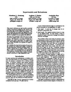
Reliability under soft (transient) errors is becoming a key concern in digital logic. The rates at which individual devices fail can be statistically estimated or empirically measured in terms of the soft error rate (SER). However, not every failure results in circuit errors, due to several masking mechanisms. Therefore, reliability can be improved by increasing the amount of masking in a circuit. For example, earlier design methods such as TMR [15] and quadded-logic [14] add significant redundancy to increase the logic masking in the circuit. We observe that an increase in logic masking does not necessarily require an increase in area. In this paper, we focus on restructuring techniques that take advantage of circuit flexibility in the form of observability don’t-cares (ODCs) to increase logic masking while incurring minimal area overhead. In order to guide synthesis techniques, we need fast methods for targeting critical areas of the circuit and re-evaluating SER after each logic transformation. Several reliability evaluation tools have been presented recently [16, 17, 8, 12]. However, their algorithms cannot be practically used to guide synthesis applications. They often rely on detailed electrical modeling and use layout and technology mapping information not available during synthesis. Motivated by these differences, we develop a fast, technology-independent SER evaluator that is designed for use in logic synthesis. Figure 1 describes our overall reliability-aware synthesis methodology. Our techniques are driven by bit-parallel logic simulation to compute signatures and don’t-care masks for all nodes in the circuit. Signatures are used to derive node controllability information, and don’t-care masks give us node observability information — to-
Figure 1: Our reliability-aware synthesis methodology. gether these facilitate linear-time computation of circuit reliability. In addition, we compute a measure called node impact to identify critical areas of the circuit for resynthesis. We resynthesize critical regions of the circuit using ODC-based logic cloning. A key insight is that logic masking is intimately related to the observability of a node. We take advantage of this fact by finding nodes within logic circuits which cover other nodes up to observability don’t-cares and facilitate a form of logic cloning. Results show that several ODCbased logic covers exist for almost every node in a circuit. In addition, we use our reliability evaluator to guide a technique known as local rewriting in order to improve reliability and area. Our SER algorithms provide support for the incremental use model according to which the reliability impact of local changes in circuits can be assessed on the fly. When a node is changed in a circuit the SER can be incrementally updated by simply re-simulating and propagating the error through its fanout cone. In addition, we propose a means for evaluating the susceptibility of a subcircuit in order to quickly evaluate potential changes and select a node with the most promise for improvement. Our main contributions are: • A fast, incremental reliability evaluator based on bit-parallel simulation that can be used stand-alone or integrated with logic synthesis.
• A novel technique based on observability don’t-cares to improve reliability with minimal logic replication. • A reliability-guided synthesis tool based on powerful local logic transformations, which improves reliability while decreasing area. The remainder of this paper is organized as follows: Section 2 describes previous work in reliability evaluation and reliabilitydriven synthesis. Section 3 gives background in bit-parallel simulation and signatures. Section 4 presents our reliability evaluation methodology. Section 4.4 presents reliability evaluation in the presence of multiple errors in the circuit. In Section 5, we propose two synthesis-based strategies we use to improve reliability. We propose a technique we call ODC-based logic cloning in Section 5.1. In Section 5.2 we describe guiding local rewrites to improve area and reliability. Section 6 presents empirical results, and Section 7 concludes the paper.
2.
PREVIOUS WORK
Recently several pioneering SER computation tools have appeared in the literature, examples include SERA [17], FASER [16], MARSC [8], and the tool from [12] based on SER-descriptors (SERD). These tools use SPICE simulation for gate pre-characterization, i.e., to determine the probability with which a single-event upset (SEU) causes an erroneous glitch in a circuit and to determine the probability that such a glitch propagates through a gate under the main masking mechanisms. These masking mechanisms were identified in [13]. • Logic masking: when glitches occur in a non-sensitized portion of the circuit. • Electrical masking: when a glitch becomes attenuated and does not propagate through due to the gates’ electrical transfer characteristics. • Temporal masking: when the result of glitch does not latch because of its timing within the clock cycle. This is also called latching-window masking. Several methods have been proposed to reduce the impact of soft errors on logic circuits. In [11], the authors use the algorithm from [12] to selectively size gates and flip-flops. Gate sizing increases the stored charge of constituent transistors such that low-energy particle strikes are less likely to affect the state. Gate sizing uses electrical masking to reduce the susceptibility to soft errors. Generally, circuit reliability can be improved by adding logic redundancy. Two classic techniques, triple-modular redundancy (TMR) and quadded-logic [15, 14], add redundancy by systematically replicating logic. Quadded logic is a paradigm in which each gate is replaced by a network of four gates which logically mask single errors. TMR involves replicating the entire circuit thrice and using a majority voter block to choose the most common output. This technique will mask any SEU in the main circuit. Cascaded TMR (CTMR) can be used to mitigate errors in the voter block as well. Mohanram and Touba [9] propose a more cost-effective version of this technique, where only susceptible nodes are triplicated (or duplicated in some cases). However, even partial replication can result in large area overhead without careful node selection. Most recently, Almukhaizim et al. [2] proposed optimizing SER using circuit rewiring, i.e., logic transformations that reconnect wires without modifying gates. This work is apparently the first illustration of reliability-guided synthesis, but has a number of limitations. Rewiring is much more restrictive than other synthesis techniques, e.g., compared to rewriting, which can also add and remove gates.
3. BIT-PARALLEL SIMULATION
We utilize bit-parallel manipulation of signatures extensively in our work to compute reliability, target critical areas of the circuit, and identify matching nodes for resynthesis. Previous authors [18, 10, 4] used signatures to check equivalence and prune non-equivalent nodes. In [18, 10] don’t-care information is encoded in signatures to merge nodes in the presence of don’t-cares. A given node f in a logic circuit can be characterized by its signature, S f (denoted SIG in Figure 2), i.e., logic values observed in response to K input vectors X1 · · · XK , S f = { f (X1 ), . . . , f (XK )}. Here, f (Xi ) = {0, 1} indicates the output of f for a given input vector. Typically, random simulation is used to generate the input vectors. We set K = 2048 in this paper, this value can be determined on a case-by-case basis or set by an engineer. Bit-parallel operations are used to derive signatures for each node in a circuit. For instance, signatures can be AND-ed or OR-ed using bitwise operations. For a circuit with N nodes, the time complexity of generating signatures is O(NK). This logic-simulation signature is a partial specification of the Boolean function that the node realizes. If the simulation were exhaustive, then the specification would be complete. We can also compute don’t-care masks using simulation. ODCs occur when the value of an internal node does not affect primary outputs for a certain input pattern. For example, in a circuit that computes AND(a, OR(a, b)), the output of the OR gates does not affect the primary output when a = 0. For a node f , S∗f = {X1 6∈ ODC( f ), . . . , XK 6∈ ODC( f )}. When an input vector Xi is in the don’t-care set of f , that bit position is denoted by a 0. Don’t-care masks are denoted ODC in Figure 2. We use the algorithm from [10] for computing the ODC mask of a set of nodes in the circuit. This algorithm involves a reverse topological traversal of the circuit where, for each input of a node, a local ODC mask is computed and then bitwise ANDed with the global ODC mask at the output of the node. The local ODC mask is derived by flipping each value in the signature to see if the output of the gate changes. Don’t-cares are represented by a 0 in the ODC mask and cares are represented by 1.
Figure 2: Signatures, ODC masks, and testability information associated with circuit nodes.
E XAMPLE 1. Figure 2 presents a sample signature and accompanying ODC mask for each node of the circuit. The ODC of c is derived by obtaining ODC’s via nodes f and g respectively and then ORing the two. The local ODC via f is 10101100. When this is ANDed with the ODC mask of f , we get the global ODC via f 00000100. Similarly, the ODC via g is 01110101 and the global ODC via g is 01110101. We get the ODC mask of c by ORing the ODCs via f and g, which is 01110101. Note that reconvergence can cause ODC simulation to produce incorrect ODC masks. However, one can handle reconvergence by performing exact downstream simulation from each node. Although this requires more computation, such simulation can be heuristically limited by the number of downstream levels visited. We utilize bit-parallel manipulation of signatures extensively in our work to compute reliability, target critical areas of the circuit, and identify matching nodes for resynthesis. Previous authors [18, 10, 4] used signatures to check equivalence and prune non-equivalent nodes. In [18, 10] don’t-care information is encoded in signatures to merge nodes in the presence of don’t-cares. In the next section, we show how to use signatures and don’t-cares to derive testability information used in our SER calculations.
4.
RELIABILITY EVALUATION
Here, we present our reliability evaluator that is specifically designed for logic-level evaluation. The discussion includes design objectives, fault modeling, and SER algorithms.
4.1 Requirements for Logic-Level Reliability Evaluation
As soft errors become more common in circuits, we need measures earlier in the design flow to ensure reliability. While other forms of masking (such as electrical and timing masking) are closely related to the layout of the circuit, logic masking can be analyzed earlier in the design flow. Furthermore, as circuits are clocked at faster speeds and gate threshold voltages decrease, electrical and timing masking become weaker while logic masking remains a dominant mechanism of error mitigation in any technology. We identify three main requirements for the integration of reliability evaluation with logic synthesis. These in turn motivate our fault model and computation techniques. • Logic-level fault modeling: Existing tools use laborious SPICEbased gate characterizations to model soft errors. For example, the tool from [12] models faults as an averaged glitch waveform, described using a probability distribution over the distribution of Weibull parameters. Such detailed fault models are difficult to translate into synthesis concerns. Therefore, we need a transient fault model that directly describes the effects of soft errors on logic-level behavior [12]. • Scalable re-evaluation: In synthesis, a netlist can be transformed through several iterations of incremental changes. Reliability evaluation becomes a bottleneck if small changes require re-computation of the circuit’s decision diagram or enumeration of all paths. Further, the symbolic techniques from [5, 16, 8] are memory- and time-intensive due to inputspace explosion. Re-evaluating circuits using these methods would severely limit the number of changes considered. • Technology independence: In order to choose between design decisions during synthesis, we need evaluators that predict trends without detailed technology or layout information. Existing tools report prototypes that only work with a
single process technology and limited sets of gates (usually only 3)[16, 12]. We propose a reliability evaluator that targets each of these requirements. It uses a probabilistic logic-level fault model for both single and multiple fault assumptions that allows efficient reasoning about error. A fast bit-parallel simulation engine is used to implement a linear time algorithm for SER evaluation and incremental methods of updating reliability after changing circuits. In order to achieve technology independence, we focus on logic masking.
4.2 Logic-Level Fault Model for Soft Errors
We propose a logic-level fault model based on the standard stuckat (SA) fault models. For every clock cycle, we assume that each node g in the circuit has a temporary single SA-1 (TSA-1) fault, with probability Perr1(g) if g is controlled to 0 and a temporary SA-0 (TSA-0) with Perr0(g) otherwise. These faults can occur randomly in each clock cycle. Due to the resemblance to SA faults, TSA faults inherit the wide applicability of SA faults. For instance, in a cycle where a node n is controlled to 1, Perr0(g) can be the probability of a bit flip due to a particle strike. While the TSA model focuses on logic masking, it can also can also incorporate other masking mechanisms if they are deemed important at the logic level. Electrical masking causes low-energy glitches to dissipate after three to four levels of logic [12]. This effect can be approximated by derating Perr0 and Perr1 by a factor pd (g, neighbors(g)), dependent on near-neighbor gates. Timing masking is moderated (more than electrical masking) by the logical path through which an error propagates. However, Zhang et al.[16, 8] successfully demonstrated the incorporation of timing masking, by dividing the probabilities of error by a constant dependent on the clock period. We can capture timing masking similarly after deriving error probabilities. Given the TSA faults, our aim is to compute the SER of the entire circuit by considering primarily logic masking. Our SER is given as a probability of error per cycle. However this can easily be converted into units of FIT, or failures per 109 seconds. If the soft error probability per cycle is p, then the expected number of failures per 109 seconds is simply p × f req ∗ 109 where f req is the clock frequency. We also consider multiple temporary faults (TMSA). Here, each gate has independent probabilities of Perr0(g) and Perr1(g). For instance, the probability of gates g1 and g2 experiencing TSA-0 simultaneously is Perr0(g1 )Perr0(g2 ).
4.3 SER and Sensitivity Analysis
In this section we use testability measures, computed through bit-parallel simulations, to develop an SER evaluation method whose runtime is linear in the size of he circuit. We also motivate and compute a measure for the impact of an internal node on the SER of the circuit. Due to space constraints, SER formulas are given for a single output, however, as in [16, 17, 8] we can compute the SER on each bit and take the average. Testability measures originated in automatic control theory and are often used in circuit testing for guiding ATPG programs [3]. In testing, an estimation of the number of input vectors that result in a node f being 0 is f ’s 0-controllability. The observability of a node measures the likelihood that the node itself controls the output. Together observability and controllability define testability. In other words, the number of test vectors for an error is the number of vectors that simultaneously sensitize and propagate the error. However, counting the number of test vectors for a fault is a computationally complex problem. Therefore, we propose to analyze the testability probabilistically by using signatures computed
through bit-parallel simulations. For a node f in circuit C, and input distribution i, we denote its 1controllability as coni1 ( f ) and compute it by counting the number of zeros in the signature: con1i ( f ) = numOnes(S f )/K
(1)
The 0-controllability is denoted coni0 ( f ) and can be computed as 1−coni1 ( f ). The subscript i denotes the input distribution which we omit for notational convenience for the remainder of this paper. We assume uniformly random inputs although simulations can be conducted for any input distribution. In addition to the controllability of a node, we also define the joint b1 , b2 -controllability two nodes f1 and f2 , denoted conb1 b2 ( f1 , f2 ) as the probability that f 1 is sensitized to b1 and f2 is sensitized to b2 . The joint controllability of the inputs of a gate can be used to accurately compute the controllability of the output. Joint controllability of a pair of signals is computed as follows: con11 (x, y) = numOnes(Sx &Sy )/K
(2)
Joint controllability is necessary for considering signal probabilities in the presence of reconvergent fanout. Reconvergent fanout creates correlations between signals that can only be captured in a joint probability distribution. The use of simulations ensures that we obtain accurate joint probabilities as the number of simulation vectors grows, by the law of large numbers. The observability of a node is the probability that the value at the node is propagated to the primary output. In the case of multipleoutput circuits, this analysis can be separately done for each output, but for the purposes of this definition we assume a single output. The observability of a node is computed by counting the number of ones in its ODC mask. obs( f ) = numOnes(S∗f )/K
(3)
Together, the observability and controllability information can tell us about the testability of a node. The 1-testability is computed by counting the number of positions where both the ODC mask and signature have a 1, the 0-testability is the number of positions where the ODC mask has a 1 and the signature has a 0. test1 ( f ) = numOnes(S∗f &S f )/K
(4)
E XAMPLE 2. Consider the circuit in Figure 2. Node g has signature Sg = 01011011 and ODC mask S∗ g = 01000100. Therefore, con0 (g) = numOnes(Sg ) = 5/8, con1 (g) = 3/8, obs(g) = numOnes(Sg∗ ) = 2/8, test0 (g) = 1/8 and test1 (g) = 1/8. If we assume that each node g has TSA-0 an TSA-1 probabilities Perr0(g) and Perr1(g), we can write the SER as a sum of error contributions from each node g in the circuit C. � � Perr(C) = ∑ test1 (g)Perr0(g) + test0 (g)Perr1(g) (5) g∈C
Since test0 and test1 include error sensitization and propagation conditions, Equation 5 accounts for the possibility of errors being logically masked before reaching the output. We summarize the SER algorithm for TSA faults below: 1. In topological order, for each node in C, compute signatures and controllabilities. 2. In reverse-topological order, for each node in C, compute ODCs and observabilities. 3. For each node in C, compute the testabilities.
4. For each node g in C compute its error contribution : test1 (g)Perr0(g) + test0 (g)Perr1(g) 5. Sum error contributions of each node to obtain the SER. E XAMPLE 3. The test0 and test1 measures for all of the nodes in the circuit are given in Figure 2. If we suppose that each gate has TSA-1 probability p and TSA-0 probability q then, the total probability of error is 2.5p + 3.75q. In addition to the SER, we compute the impact of each node in a circuit. The impact of a node on the SER of the circuit is proportional to 1) the probability that faults arrive at the node and 2) the probability that those faults are observed as errors at the output. In other words, a gate has high impact if many observable faults “flow” through it. Therefore, we compute the probability that faults originating at other nodes get propagated to n In other words, we treat n as a primary output and compute the relative testability of each node g with respect to n, denoted test0 (g, n),test1 (g, n). The relative testability is computed as follows: test1 ( f , n) = numOnes((S∗f &Sn∗ )&S f )/K
(6)
Intuitively, the probability of any fault in the fanin cone of n, reaching the output is limited by the observability of n. In general, nodes closer to the primary output are more observable than nodes closer to the primary input. However, a node f in the fanin-cone of n may have observability greater than n due to high fanout. In this case, the probability of the fault being observed on a path through n is still limited to the observability of n. Thus, we can mask the ODC of nodes f by the ODC mask of n to compute relative testability. Therefore, the impact of n on the SER is: � � impact(n) = ∑ Perr0(g)test1 (g, n) + Perr1(g)test0 (g, n) g∈ f anin(n)
The impact algorithm is summarized below:
(7)
1. For each node f in the fanout cone of n, compute test0 ( f , n), test1 ( f , n). 2. For each node f , compute its contribution: Perr0(g)test1 (g, n) + Perr1(g)test0 (g, n) 3. Sum the contribution to the impact. E XAMPLE 4. For the circuit in Figure 2, test1 (g, h) is given by numOnes((01000100 & 01110111) & 01011011) = 1/8. Suppose that each gate has a probability of TSA-1 p and TSA-0 q. Then, the impact of h is (1/8)p + (1/8)q + (2/8)p + (5/8)q = (3/4)q + (3/8)p. This impact measure allows us to target critical areas of the circuit. If the obs(n) is decreased, then fewer fault coming in to n will be propagated to the output. If a subcircuit C 0 is hardened, the errors propagating to nodes in the fanout of C 0 will decrease and obs of nodes in the fanin cone of C 0 also decrease. Therefore, once local changes are made, these measures are incrementally updated as follows: 1. Update the signatures and controllabilities in topological order through the fanout cone of C 0 . Only propagate changes through bits whose values change. 2. Update the ODCs and observabilities in reverse-topological order through the fanin cone of any changed signatures.
4.4 Multiple Errors and Mutual Masking
In this section we consider multiple simultaneous faults using the the TMSA fault model. For TMSA faults, error cancellation due to mutual masking can change fault sensitization. To account for such cancellation, we compute the faulty observability, faulty controllability, and cumulative error probabilities. Given the controllabilities of nodes, we compute the probability of error at each node in the circuit due to a combination of errors in the fanout cone of the node in topological order. We compute Perr0in and Perr1in , the probabilities of an erroneous 0 or an erroneous 1 coming into each node n due to errors in previous gates. The probability of error at the output of each gate is a culmination of the probabilities of error at its inputs and error probability at the gate itself. For an AND gate g with independent inputs x, y, output z, and error probability Perr1in (z) considering errors at its input and gate is: F 0 con1 (z) = con0 (x)con0 (y)Perr1in (x)Perr1in (y)
Perr(C) = Perr0in (o(C))con1 (o(C)) + Perr1in (o(C))con0 (o(C)) (9) We summarize our SER algorithm for the TMSA faults below: 1. For each node, compute signatures and controllabilities. 2. In topological order compute Perr0in and Perr1in . 3. Weight Perr0in (o(C)) by the probability that the correct circuit C would output 1, i.e., con1 (o(C)) and similarly for Perr1in (o(C)) to derive the SER for that output. Therefore, the impact of a gate on the SER of the circuit is given by Equation 10. Note that since the error propagation analysis handles the cancellation of errors, the impact is easier to calculate in the multiple error case. impact(n) = Perr0in (n)Fobs0 (n) + Perr1in (n)Fobs1 (n)
(10)
If the Fobs of n is decreased, then fewer errors coming in to n will be propagated to the output. After an update the faulty controllability and faulty observability of nodes in the fanout and fanin are also recomputed. This algorithm requires only two additional topological traversals to compute the faulty probabilities, therefore it also runs in linear time.
+con0 (x)con1 (y)Perr1in (x)(1 − Perr0in (y)) +con1 (x)con0 (y)(1 − Perr0in (x))Perr1in (y) C0 con1 (z) = con0 (x)con0 (y) [1 − Perr1in (x)Perr1in (y)]
5. SYNTHESIS FOR RELIABILITY
+con0 (x)con1 (y) [1 − Perr1in (x)(1 − Perr0in (y))]
We present two synthesis techniques that improve the reliability of circuits by leveraging our fast evaluation methods. The first technique chooses high-impact nodes and decreases their observability by using redundancy already present in the circuit. The second technique guides logic rewriting [7] to optimize for reliability in addition to area.
+con1 (x)con0 (y) [1 − (1 − Perr0in (x))Perr1in (y)] Fcon1 (z) = F 0 con1 (z)(1 − Perr0(z)) +C 0 con0 (z)(Perr1(z)) Ccon1 (z) = F 0 con0 (z)(Perr1(z)) +C0 con1 (z)(1 − Perr0(z)) Perr1in (z) = (con0 (z) − Fcon1 (z))/con0 (z)
In topological order, if we compute the Perr0in and Perr1in of all the gates up to the primary output of a circuit, then we immediately have an algorithm for the SER of a circuit. The SER for the output of a circuit C, o(C), is given by
5.1 ODC-based Logic Cloning
(8)
Recall that Perr0(z) and Perr1(z) are the fault probabilities of z itself. We call Fcon1 (x) the faulty 1-controllability of x, and Ccon1 (x) the correct 1-controllability of x. If the inputs are correlated, then as in the previous section, we can use the joint controllabilities and joint probabilities of error. If the errors are assumed to be independent then Perr00(x, y) = Perr0(x) ∗ Perr0(y). Correlations between different errors can be taken into account by computing correlation coefficients between pairs of signals. The coefficients need only be computed for signals that are in the same level of a levelized circuit. For instance, if the signals are correlated then Perr00(x, y) = Perr0(x)Perr0(y)Cx,y where Cx,y is the correlation between the errors on x and y. Note that Fcon1 (x) + Ccon1 (x) + Fcon0 (x) +Ccon0(x) = 1. Other types of gates can be analyzed similarly on a case by case basis, or we can locally use transfer matrices [5] in the general case to compute the output error of a gate given the input error and input probability distribution. In addition, we can compute the probability that errors at a gate will be observed at the output including the probability that the error will be canceled in the future. For an AND gate g with independent inputs x, y, output z, the probability of the error being observed Fobs(x) is computed reverse topological order given Fobs0 (z): Fobs0 (x) = (Fcon1 (y) +Ccon1 (y))Fobs0 (z) Given this analysis of how multiple errors propagate and cancel, we can derive the SER and calculate impact that gates have on the error probability.
We propose a novel logic replication strategy that increases reliability by replicating nodes using redundancy already within the circuit. Hence, we get logic cloning by strategically adding single gates to the immediate fanout of critical nodes. First, we discuss the concept of logic covers in the presence of ODCs. Then, we explain how to utilize the ODC masks already computed for our reliability evaluator to find logic covers. We increase logic masking, literally the number of don’t-cares in the ODC mask, through targeted replication by identifying logic covers in a circuit. Given two nodes g and f that realize Boolean functions G and F respectively, we say that G logically covers F if the following relationship holds: F⊆G In other words, G is 1 for every input pattern that makes F = 1. In the presence of ODCs, this can be generalized to: F ⊆ C(G) + ODC(G) Here, C(G) and ODC(G) represent the care and observability don’tcare set for G respectively. In other words, G covers F if and only if G is 1 or a don’t-care wherever F is 1. We define node G as an anti-cover of node F when: C(G) − ODC(G) ⊆ F In the special case where F = G, G is a cover and anti-cover of F.
We exploit logic covers that exist within a circuit. Our strategy, uses signatures to quickly identify many possible replication opportunities and use the impact measure to choose the opportunity that gives the most improvement. Note that the impact measure can be used in two different ways, the first way is to target high-impact areas of the circuit. Second, we can use impact to decide between resynthesis choices. For a high-impact node x, we find other candidate nodes that it covers or anti-covers. Given a candidate node y that x covers, we can add redundant logic by transforming node x into OR(x, y). Because y ⊆ x, OR(x, y) = x. Therefore, we achieve replication of x through the addition of a single gate. This relation can be expressed and identified using signatures: D EFINITION 1. Sy ⊆ Sx if and only if Sx |Sy = Sx where | represents bit-wise OR. Similarly, if x is an anti-cover of y, we can transform node x into AND(x, y). To generalize, we identify y such that x = OP(x, y) where OP can be AND or OR. In the trivial case where x is chosen as a candidate cover for itself, the redundant logic generated by x = OP(x, x) will not lead to reliability improvements since sensitized paths in x’s fanin cone will remain unchanged for all input stimuli. At the other extreme, if x and y have disjoint fanin cones and x = y, then all errors that cause x to flip erroneous from a 0 to a 1 will be masked when x is replaced by AND(x, y). Similarly, all errors which cause x to flip from a 1 to 0 can be masked by OR(x, y). In the more general case of x = OP(x, y) where x and y are different nodes, the impact of x and the portion of its fanin that is disjoint from y will be reduced according to the operation. This occurs because sensitized paths in the fanin cone that include x but not y will benefit from the extra logic masking generated by OP(x, y). In contrast to techniques like TMR, it is not necessary for replicated nodes to have the same function. We drastically increase the number of candidates by allowing nodes that simply cover other nodes. For instance, suppose x has signature Sx = 11000 and Sy = 11001. By definition, x covers y, therefore x can be replaced by AND(x, y), in this case all 0 to 1 flips on the third and fourth input vectors will be masked, as long as they are not propagated through both x and y. Similarly if y is replaced by OR(x, y) then all 1 to 0 flips in the first two bits will be masked. In cases where multiple covers exist for a node, we break ties using the change in impact between the replicated and old nodes. The expression for impact from Equation 10 considers the change in observability and error propagation probabilities conditions. Since we maintain signatures for each node based on simulation along with observability information in our evaluator, we can quickly find covers that use don’t-cares. First, simulation vectors implicitly handle satisfiability don’t-cares because impossible input combinations will not occur in a node’s signature. Also, we can exploit the observability information stored at each node by noting that input vectors where a node is unobservable at the outputs indicate ODCs. Using this circuit flexibility allows us to find covers or anti-cover for x where x 6= OP(x, y) but the functionality of the entire circuit remains the same. Figure 3b contains an example where replicated logic for node a is derived by utilizing don’t-care values stored with its signature. Replication derived through signature manipulation needs to be formally verified. We use a SAT solver to prove equivalence by constructing miters along a cut in the fanout cone of x between the original circuit and the new circuit with cover OP(x, y). The cut is chosen where the logical differences between OP(x, y) and x saturate and the cut is extended if new differences are identified from
counter-examples found during equivalence checks. In the worst case, miters need to be constructed at the primary outputs of the fanout cone. This approach to equivalence checking is discussed in more detail in [10].
5.2 A Strategy Based on Rewriting
In this section we develop a synthesis strategy that optimizes area and reliability simultaneously. In [7], an efficient synthesis strategy is developed that generates substantial area reductions by performing several local logic rewritings (or restructurings). First, a 4-input cut is derived for a given node in a circuit, which defines a one-output subcircuit. Several candidate, functionally-equivalent subcircuits are considered as potential replacements. In order to effectively guide this strategy, we harness the scalability of our reliability evaluator by computing the effect of hundreds of candidate rewrites on circuit reliability. We only accept candidates that improve reliability without increasing area.
Figure 3: a) Rewriting a subcircuit to improve area. b) Finding a candidate cover for node a using simulation by exploiting don’t-care values in its signature (shown as crossed out bits). This candidate can be later verified using SAT. As shown in Figure 3a, one can rewrite the original subcircuit with three gates into a subcircuit with two gates. In general, it is also possible for the newly rewritten subcircuit to share logic with the rest of circuit. By using structural hashing described in [6], one can quickly identify new nodal equivalences for the rewritten subcircuit and further reduce area. In Figure 3a, observe that the impact of the two equivalent subcircuits on the SER is different. The circuit with redundant input a allows for more logic masking. We recognize that there is an inherent trade-off between reliability and testability. To this end, our synthesis techniques may increase the difficulty of post-manufacturing test. However, this trade off may be necessary if reliability challenges drastically increase in future technology generations, as currently expected. On the positive side, improvements in BIST and other techniques for circuit test can offset the effect of reliability improvement on testability.
6. EMPIRICAL RESULTS
In this section we present empirical results for reliability evaluation, ODC-based replication, and local rewriting. Table 1 is a comparison of runtimes on standard benchmarks between our tool and other popular SER evaluation tools In [12], the authors report results per input vector. We therefore multiply their normalized runtimes by 2048 (the number of random input vectors we use) to obtain comparable times. We use our TMSA fault model and the corresponding algorithm to derive Table 1. These results show that our runtimes differ by several orders of magnitude from those of other evaluators. One of the reasons is that our internal bit-parallel simulations allow our algorithm to run in linear time. Further, we
do not use decision diagrams or complex gate characterizations in our calculations. Circuit i1 i2 i3 i4 i5 i6 i7 i8 i9 i10 c432 c880 c1355 c1908 c3540 c6280
Ours 0.022 0.000 0.057 0.072 0.046 0.059 0.067 0.20 0.013 0.015 0.007 0.007 0.014 0.015 0.000 1.000
Time(s) SERD FASER 20 — 20 — 20 — 20 — 20 — 20 — 20 — 20 — 40 — 60 — 10 22 10 — 20 40 20 66 60 149 120 278
Figure 4: Comparison of SER trends on inverter chains produced by SERD and our evaluator. Circuit
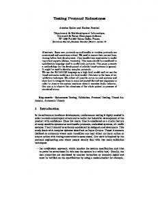
Table 1: Runtime comparisons with several reliability evaluators from the literature. We validate our logic masking approximations by comparison with the exact reliability evaluator from [5]. While the method in [5] does not scale to large benchmarks, we use small circuits and logic blocks commonly found in larger benchmarks for comparison. Table 2 shows representative with perr = 0.05 for each gate. In order to incorporate gate characterization information for baseline gate error probabilities, we extrapolate from the characterization results of [12]. The program from [12] only characterizes three gates, we use an average SER value of 4E − 7 for all gates. Their characterization was done using SPICE on 130nm, 1.2Vdd technology. However, we note that the reliability evaluators from [17, 16, 12] all report error rates that differ by orders of magnitude. SERA reports SER values on the order of 10−3 for 180nm technology nodes, and FASER reports SER on the order of 10−5 for 100nm. Further, we use mechanisms for electrical derating by scaling our error probabilities at nodes by a small factor to obtain trends similar to [12]. In Figures 4, we compare trends on inverter chains of growing length. Exactly one path is always sensitized in an inverter chain. Therefore we can determine the derating factor due to electrical masking alone using such chains. Table 3 shows improvements in SER and area overhead due to logic replication. The benchmarks are all initially structurally hashed using [1]. The first set of results are for exact covers, the second set of results considers equivalences up to ODC values and uses AND/OR gates as appropriate. For exact covers, we average of 29.1% SER improvement with only 5% area overhead. The improvements for the ODC covers are 39.8% with an average area overhead of 13.1%. This is in contrast to partial TMR techniques such as [9] which achieve an average of 91% improvement using 104% increase in area. Our results suggest that guiding reliability carefully can offer more gain per unit area added to logic circuits. Table 4 shows the ability of our fast reliability evaluations to Circuit C17 majority parity mux xor4 and4
Exact SER 0.154 0.095 0.398 0.093 0.244 0.141
Approx SER 0.135 0.095 0.397 0.102 0.244 0.141
%error 12 0.0 0.25 8.8 0.0 0.0
Table 2: Comparison of our approximate SER computation with an exact evaluator on small circuits.
cordic b9 C432 C880 C499 C1908 C1355 alu4 i9 C3540 dalu i10 des Average
SER
Area
5.334 E-5 1.89E-5 1.39E-3 5.17E-5 4.24E-4 1.92E-4 1.09E-2 6.12E-4 1.66E-4 2.38E-3 3.08E-4 1.0E-4 9.84E-5
84 114 215 341 432 432 536 740 952 1055 1387 2824 4252
With exact covers % improv % area SER overhead 1.7 1.2 18.1 14.9 37.6 14.0 9.6 0.9 1.0 3.2 5.9 9.0 25.3 9.0 55.9 0.9 65.4 6.6 31.1 2.2 74.3 1.2 40.4 5.4 11.4 2.9 29.1 5.5
With approx ODCs % improv % area SER overhead 27.3 45.2 30.7 31.6 38.7 14.9 13.1 2.3 32.2 20.6 32.4 24.1 30.7 8.6 55.9 1.6 65.4 6.6 49.4 3.6 74.3 1.2 40.4 5.6 26.7 4.4 39.8 13.1
Table 3: Improvements in reliability with ODC-based logic replication.
guide a general synthesis technique such as local rewriting. Note that the global reliability impact of each local change has to be considered before any rewrites are done. We check hundreds of rewriting possibilities and only keep those that simultaneously improve area and SER simultaneously. Hence, scalability is a key for this application. Table 4 shows improvements in SER with an average of 2.3% decrease in area when a synthesis strategy based on rewriting is used. For instance, on alu4, a circuit with 740 gates, we achieve 30% better reliability while reducing area by 0.5%. While it is often thought that area optimization techniques hurt reliability, our results show that area and reliability can be simultaneously optimized by careful guiding. This emphasizes a key observation from our work that a decrease in area does not necessitate a decrease in logic masking. Circuits
SER
Area
alu4 b1 b9 C1355 C3540 C432 C499 C880 cordic dalu des frg2 i10 i9 Average
6.12E-4 8.62E-6 1.89E-5 1.09E-2 2.38E-3 1.38E-3 4.23E-4 5.17E-5 5.33E-5 3.08E-4 9.84E-5 1.98E-5 2.00E-4 1.66E-4
740 14 114 536 1055 215 432 341 84 1387 4252 1228 2824 952
No. rewrites 13 0 8 97 23 68 37 7 5 58 282 96 143 83
%improv SER 29.3 0.0 6.8 1.2 5.8 5.5 0.0 0.2 1.2 24.0 11.2 27.9 5.0 31.4 10.7
%area decrease 0.5 0.0 0.9 9.0 0.9 1.4 0.5 0.0 1.2 3.2 0.1 2.0 0.6 11.7 2.3
Time (s) 24.5 0.2 0.3 37.6 51.5 12.1 13.0 5.4 0.5 35.0 12.3 8.9 16.7 35.3 18.1
Table 4: Improvements in SER and area by applying reliabilityguided rewriting to existing circuits.
7.
CONCLUSIONS
8.
REFERENCES
We have presented a new technology-independent fast reliability evaluator designed for logic synthesis. We have also presented a method for identifying critical high-impact areas of the circuit to target for replications. Our algorithms are able to handle both single and multiple errors per cycle. As demonstrated by the experimental results, we produce SER trends similar to those in [12, 11], but 2 to 3 orders of magnitude faster. We also proposed a novel strategy for replicating vulnerable nodes with the addition of a single gate for each replicated node. This strategy manipulates previously-stored signatures to find observability don’t-care values. We found that this technique improves reliability by an average of 29-40% while using only 5-13% area overhead, depending on the desired trade-off. We successfully applied our reliability evaluation method to a popular synthesis technique known as local rewriting. Our techniques can also improve the reliability of existing circuits by applying reliability-guided rewriting — our experiments show a 2.3% area decrease and a 10% improvement in reliability. [1] Berkeley Logic Synthesis and Verification Group, “ABC: a system for sequential synthesis and verification”, http://www.eecs.berkeley.edu/∼alanmi/abc/. [2] S. Almukhaizim, Y. Makris, et al., “Seamless Integration of SER in Rewiring-Based Design Space Exploration,” ITC 2006. [3] M. Bushnell, V. Agrawal, Essentials of Electronic Testing, Kluwer, 2000, pp. 129-150. [4] E. Goldberg, M. Prasad, R. Brayton, “Using SAT for combinational equivalence checking”, DATE 2001, pp. 114-121. [5] S. Krishnaswamy, G. F. Viamontes, et al., “Accurate Reliability Evaluation and Enhancement via Probabilistic Transfer Matrices”, DATE 2005, pp. 282-287. [6] A. Kuehlmann, V. Paruthi, et al., “Robust Boolean Reasoning for Equivalence Checking and Functional Property Verification,” TCAD vol. 21(12), 2002, pp. 1377-1394. [7] A. Mischenko, S. Chatterjee, R. Brayton, “DAG-aware AIG rewriting: A fresh look at combinational logic synthesis”, DAC 2006. [8] N. Miskov-Zivanov, D. Marculescu, “MARS-C: Modeling and Reduction of Soft Errors in Combinational Circuits,” DAC 2006, pp.767-772. [9] K. Mohanram, N. A. Touba, “Partial Error Masking to Reduce Soft Error Failure Rate in Logic Circuits” DFT 2003, pp. 433-440. [10] S. Plaza, K-H. Chang, et al., “Node Mergers in the Presence of Don’t Cares” ASP-DAC 2007. [11] R. Rao, D. Blaauw, D. Sylvester, “Soft Error Reduction in Combinational Logic Using Gate Resizing and Flipflop Selection,” ICCAD 2006. [12] R. Rao, K. Chopra, et al., “An Efficient Static Algorithm for Computing the Soft Error Rates of Combinational Circuits,” DATE 2006, pp. 164-169. [13] P. Shivakumar, M. Kistler, et al., “Modeling the Effect of Technology Trends on Soft Error Rate of Combinational Logic” DSN 2002, pp. 389-398. [14] J.G. Tryon, “Quadded Logic,” Redundancy Techniques for Computing Systems, 1962, pp. 205-228. [15] J. von Neumann,“Probabilistic Logics and Synthesis of Reliable Organisms from Unreliable Components,”
Automata Studies, 1956, pp. 43-98. [16] B. Zhang, W. S. Wang, M. Orshansky, “FASER: Fast Analysis of Soft Error Susceptibility for Cell-Based Designs,” ISQED 2006, pp. 755-760. [17] M. Zhang, N.R. Shanbhag, “A Soft Error Rate Analysis (SERA) Methodology,” ICCAD 2004, pp. 111-118. [18] Q. Zhu, N. Kitchen, et al.,“SAT Sweeping with Local Observability Don’t-Cares”, DAC 2006, pp. 229-234.