Aug 17, 2009 - devices [18, 3]. Virtual networks can be tailored and ded- icated to different services, possibly managed by different entities [12]. This flexibility ...
Enhancing Dynamic Cloud-based Services using Network Virtualization Fang Hao, T.V. Lakshman, Sarit Mukherjee, Haoyu Song Bell Labs, Alcatel-Lucent
{fangh, lakshman, sarit, haoyusong}@alcatel-lucent.com
ABSTRACT
1. INTRODUCTION
It is envisaged that services and applications will migrate to a cloud-computing paradigm where thin-clients on userdevices access, over the network, applications hosted in data centers by application service providers. Examples are cloudbased gaming applications and cloud-supported virtual desktops. For good performance and efficiency, it is critical that these services are delivered from locations that are the best for the current (dynamically changing) set of users. To achieve this, we expect that services will be hosted on virtual machines in interconnected data centers and that these virtual machines will migrate dynamically to locations bestsuited for the current user population. A basic network infrastructure need then is the ability to migrate virtual machines across multiple networks without losing service continuity. In this paper, we develop mechanisms to accomplish this using a network-virtualization architecture that relies on a set of distributed forwarding elements with centralized control (borrowing on several recent proposals in a similar vein). We describe a preliminary prototype system, built using Openflow components, that demonstrates the feasibility of this architecture in enabling seamless migration of virtual machines and in enhancing delivery of cloud-based services.
There is a growing consensus that a significant number of services will be delivered using a cloud-computing model where users running thin-clients in their devices will access network hosted applications and services. These applications and services will be hosted in data centers located in various parts of the network. New services will be instantiated by deploying a service delivery system ondemand by dynamically allocating the necessary network and data center resources. Examples of such services are cloud-computing based on-demand gaming [2] and network supported virtual desktop applications [1]. For successful deployment of such cloud-based applications, it is important that users perceive very little delay in accessing the cloud-hosted services. Since the population of users can be highly variable, the service delivery system must be able to dynamically adapt to the changing user population by moving the application servers providing the service to the best locations (from amongst the various data centers) for the current user population. With the on-going transformation of data centers due to virtualization, we expect that applications providing the services will be run on virtual machines whose locations are dynamically determined to best match the delivery needs for the current user population. As the user population for a service changes, the best location for the virtual machines providing the service changes and the virtual machines must be migrated to new physical locations. Host virtualization software currently makes possible on-line migration of virtual machines (VMs), i.e., it is possible to move a VM between different hosting machines while the VM is running. This is achieved by dynamically checkpointing the VM state at the source host, and incrementally transferring the state to the destination host. In order to avoid connection (and thereby service) interruption, the VM maintains the same IP address during the migration. This currently limits migration to be within a LAN since there is no easy way to migrate VMs across wide area networks when the IP address is fixed. Addressing this limitation greatly enhances the flexibility of cloud-based service delivery. For example, “thin client” applications such as [1] allow users to run a VM in the network cloud, and access the VM from various devices at different locations. A flexible service delivery system would allow these VMs to migrate to different locations in the cloud depending on user locations so as to permit faster access and more efficient data delivery to users. Application service providers can also benefit from wide area mobility if virtual servers can be freely moved
Categories and Subject Descriptors H.4.3 [Information Systems]: Information Systems Applications—Communications Applications
General Terms Design, Experimentation
Keywords Virtualization, VM Migration, Data Center
Permission to make digital or hard copies of all or part of this work for personal or classroom use is granted without fee provided that copies are not made or distributed for profit or commercial advantage and that copies bear this notice and the full citation on the first page. To copy otherwise, to republish, to post on servers or to redistribute to lists, requires prior specific permission and/or a fee. VISA’09, August 17, 2009, Barcelona, Spain. Copyright 2009 ACM 978-1-60558-595-6/09/08 ...$10.00.
37
between different data centers for easy load balancing and performance optimization. As an example, consider a cloud computing service such as Amazon’s EC2 that allocates resources to customers to run cloud-based services. The load caused by such services can be bursty and may shift between different physical locations at different times. It is useful to permit the VMs that run such services to migrate between data centers to match the location of majority of current users. Note that adapting the existing mobile IP solution [7] for VM mobility is not satisfactory. In a mobile IP network, all traffic destined to a mobile device has to go through an anchoring point – the mobile’s home agent. This triangular routing not only increases the packet delivery delay but also imposes burden on the networks as well as the home agent. Although such limitations may be tolerable for enduser devices, since the traffic volume is relatively low, it is not practical for VMs since the VMs are typically servers that both send and receive a high volume of traffic. For example, consider the Amazon cloud computing example discussed before. If all VMs have to be anchored at one home agent, then VM migration across different data centers cannot benefit end users since it will only increase routing path length. Mobile IPv6 [14] addresses the triangular routing problem by requiring correspondent nodes to support mobile IP signaling and hence to track the new foreign address of the mobile. However, any transition from IPv4 to IPv6 is not likely to happen overnight, and a large portion of Internet may remain as IPv4 for the foreseeable future. In addition, servers should be designed to accommodate heterogeneous clients as it is not realistic to expect all end-user devices to implement this feature. A basic network infrastructure need then is the ability to migrate virtual machines across multiple networks in an efficient manner without losing service continuity. In this paper, we address this issue by drawing on recent advances in network virtualization that permit a router or an entire network to be logically independent of the underlying physical devices [18, 3]. Virtual networks can be tailored and dedicated to different services, possibly managed by different entities [12]. This flexibility enables better network support for new applications and faster service provisioning. Our mechanisms and architecture to support virtual machine migration are drawn on recent network architecture proposals that rely on distributed forwarding elements and centralized control [8, 9, 16, 17, 20]. Commonly, the approach in network virtualization is to slice and isolate the resources in a physical router so as to support multiple virtual routers. In our approach, we logically combine multiple geographically distributed physical devices to form a single virtualized logical router, where each physical device mimics a virtual line card with multiple virtual ports. The virtual line cards can be interconnected in a variety of ways to mimic a virtual backplane: they can be interconnected using dedicated facilities (as could be the case if the forwarding elements are in data centers), they can be interconnect using MPLS bandwidth-guaranteed paths, or they can be interconnected by tunnels through the public Internet. The distributed forwarding elements comprising the virtual router are configured and managed by a centralized controller (CC). We term such a virtual router as a Virtually Clustered Open Router (VICTOR). For convenience,
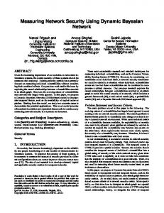
we refer to a distributed forwarding element or router as simply a forwarding element (FE). Our basic idea is the following: forwarding elements (FEs) are deployed at the various candidate hosting locations where the VM for a particular service may reside. The CC associated with these FEs controls the forwarding on all the FEs and also keeps track of the current location of all the VMs. VICTOR announces the reachability of VM prefixes through all its FEs. As a result, routers outside VICTOR choose the closest FE when routing packets destined to the VMs. Since CC knows the actual location of each mobile VM, it configures each FE to forward the traffic to the actual FE where the VM is attached. Traffic going out of the VMs are sent directly to the outside network by the FEs to which the VMs are attached. There are several advantages to this approach: First, control and forwarding planes are separated for mobile VM traffic. Unlike in the existing mobile IP solution where HAs handle both signaling and data path functions, in VICTOR signaling and routing are handled by CC and data forwarding is handled by the FEs. This is similar to the SoftRouter [16] and Openflow [17] models. These mechanisms combine the advantage of more efficient data forwarding and more flexible control. Second, triangular routing is significantly reduced for both directions. Traffic coming out of a VM is directly forwarded to the correspondent node. Traffic going to the mobile VM first reaches the FE that is closest to the correspondent node, and is then forwarded to the binding FE where the VM is currently located over the dedicated facilities between data centers. And finally, similar to the current mobile IP solution, no modification to user application or TCP/IP stack is needed, no modification to correspondent node is needed, and connectivity is not affected during and after migration. The paper is organized as follows: We first describe the proposed VICTOR architecture in Section 2. Since VMs are becoming an important component of the data center computing environment, in Section 3 we briefly discuss how to fit the VICTOR architecture into a typical data center network. We then give, in Section 4, a few examples of interesting new applications that benefit from our proposed mechanisms. In Section 5, we describe a prototype system that we built using the openflow platform, as a step toward validating the feasibility of the VICTOR architecture. We finally discuss related work in Section 6. Concluding remarks are in Section 7.
2. VICTOR ARCHITECTURE As mentioned previously, VICTOR consists of a cluster of forwarding elements (FEs) and one or more centralized controllers (CC). FEs handle data plane functions such as packet forwarding, policing and policy enforcement. They also set up a virtual backplane between each other as necessary. The CC controls routing and signaling for the VM’s IP prefixes. The entire VICTOR system of FEs and one or more CCs can be viewed as one single loosely coupled router, where the FEs are its line cards, and CCs are its control plane. However, unlike a conventional router which runs in one network, FEs can be distributed across a wide area and different networks. An FE could be a simple data forwarding device that does not implement any control plane or routing functions, or it could be be a regular router but with the VICTOR function enabled (i.e., with API that can
38
be accessed from CC for control functions). In both cases, each FE needs to have the capability of forwarding packets based on forwarding tables that are computed and downloaded from the CC. Note that VICTOR does not change the routing for prefixes which do not belong to the set of VMs that need to have migration capability.
does not announce FE-FE links to external routers, so that non-mobile VM packets are not routed by VICTOR. Internal Routing: An active VM v discovers an adjacent FE f and registers itself with the FE. The FE forwards the binding (v, f ) to the CC. The CC authenticates the binding and configures all the other FEs with the binding (v, f ). Only one active binding for each VM is allowed at a time. The VM is deregistered and the old binding is removed if it becomes inactive. Similarly the binding changes when it moves to another FE. Each FE maintains a forwarding table including local bindings for locally registered VMs and foreign bindings for remotely registered VMs. External Packet Forwarding: When FE receives a packet destined to an external IP address, the packet is directly sent out to the proper port by looking up the external forwarding table. Internal Packet Forwarding: When FE f1 receives a packet destined to VM v (after stripping off the tunnel header if such header is present), if v has a local binding, the packet is directly forwarded to v; if v has a foreign binding (v, f2 ), the packet is forwarded (using tunneling, if need be) to f2 ; if no binding is found for v, the packet is discarded.
2.1 Basic Architecture ��
�"#$%&
��
�� �� ��
�� �� ��
��� � � � � ��� �� �
��� ���
���
��� ������
��! ��
2.2 Scalability
�� ��
A natural concern for any centralized architecture is scalability. We discuss scalability issues in this section.
2.2.1 Data Plane Inbound and outbound traffic for mobile VMs are forwarded by FEs. Each FE may have a limited forwarding capacity. Once the number of mobile VMs or amount of mobile traffic at a region exceeds this capacity, more FEs can be deployed to split the load. Aside from bandwidth, the other resource limitation may be the number of tunnels that each FE can support. In our basic design, each FE may potentially set up a tunnel with every other FE to allow maximum flexibility for data forwarding. However, since such tunnel can be a simple IPin-IP tunnel, no sophisticated state needs to be maintained. Hence we do not expect this to be a serious issue. Furthermore, the VICTOR architecture does not fundamentally require a full mesh connectivity between FEs, so the number of tunnels can be reduced if necessary.
Figure 1: VICTOR architecture The VICTOR architecture is illustrated in Figure 1. The FE is the first layer-3 access and aggregation point for the mobile VMs. The FEs are typically located in different layer 3 networks. The FEs can be connected by either provisioned links or IP tunnels. To understand how packets are forwarded by VICTOR, consider two cases: Communication between two VMs, and communication between an external user client and a VM. In Figure 1, the path between source VM1 and destination VM2 is VM1-FE4-FE3-VM2. Note that such communication basically always takes the shortest path. Externally, the correspondent client node always delivers packets to its nearest FE, which in turn forwards packets to the FE of the destination VM. For example, the forwarding path from Client node to VM1 is Client-FE2FE4-VM1. Path from VM1 to Client is VM1-FE4-Client. CC keeps track of the location of all the VMs, and sets up forwarding tables on FEs accordingly. Note that unlike in conventional mobile IP architecture, here there is no distinction between home agent and foreign agent. The entire VICTOR system appears as a single virtual “agent” which handles both mobile VM address registration and packet forwarding, although its components (FEs) are geographically apart from one another. The aggregated mobile VM IP address prefixes are advertised by each FE to the external networks. The correspondent nodes from the external Internet can always choose the best path to reach VICTOR via the nearest FE. Now we describe further details of the operations of VICTOR: External Routing: Each FE advertises all the mobile VM addresses that VICTOR covers. It also calculates and maintains the best routes to the external IP addresses. This can be achieved by letting FEs participate in regular routing such as OSPF (or this can be done by the CC). An FE
2.2.2 Control Plane The central controller is responsible for registering location of mobile VMs and setting up the forwarding table on FEs. One concern is that for a large scale network, a single CC may not be able to handle all the signaling traffic load. Another concern is that CC can be a single point of failure. However, such scalability and reliability requirements are hardly unique here since CC is basically a server. Therefore many well studied solutions for server scalability and reliability are applicable here. For example, we can partition the mobile VM addresses into different ranges, so that each CC is responsible for a separate range of IP prefixes. FEs need to contact the corresponding CC for different VM addresses. In this way, the location of a VM is always maintained by the same CC, and there is no requirement for communication between CCs. The drawback of this model is that each CC may need to communicate with all FEs because in theory, the same VM can appear at any location. Alternatively, we can partition the FEs into different groups according to re-
39
3. VM MIGRATION FOR DATA CENTERS
gions, so that each CC is assigned to one FE group. In this model, since a VM can move across FE groups, CCs may need to coordinate with each other. Such geographical partitioning may be more suitable for data center deployment. In either case, we can assign one or two standby CCs for each CC so that there is always a backup in case of failure.
VMs are ubiquitous in data centers and enterprise networks. VICTOR can be of benefit in both these environments. In this section, we use the data center as an example, and outline how VICTOR can be deployed beneficially in such an environment. In a typical data center network, several border routers connect the data center network to the service provider’s network. Once packets come in from Internet via the border routers, they traverse through multiple middle boxes such as firewalls and load balancers. Packets are then switched to one of the internal servers. Depending on the application logic, internal servers can access each other to accomplish the user demanded service. For example, a web server can access an application server which in turn accesses a database server.
2.3 Across Multiple Networks We envision VICTOR to be deployed in a single network domain to allow layer 3 VM migration within the domain that hosts the data centers for cloud computing. However, it is possible to deploy VICTOR across multiple domains to allow wider mobility. When VICTOR is deployed across multiple service provider networks, it is important to ensure that VICTOR forwards packets in a way that conforms with service provider routing policies. It turns out that this is not a problem since VICTOR can rely on regular IP routing between FEs and use IP tunnels for its virtual backplane. FEs can route packets between each other as long as connectivity is provisioned. For example, if VICTOR is used to enable VM migration between large enterprise networks, it may utilize any available VPN resources between different sites. However, if certain applications require better QoS treatment, then such agreements and provisioning need to be in place. But again, VICTOR is designed to utilize whatever underlying pipe is available.
3.1 Internal Migration Current VM technologies support migration within a LAN, so no additional mechanisms are needed for small data centers where all devices are contained in one subnet. However, it is more common for a data center to have multiple layer 3 networks due to scalability and policy reasons. In this case, layer 2 switches are used to connect hosts in the same subnet, and layer 3 routers are used to connect different subnets. To allow VM migration across subnets inside a data center, FEs can be deployed at the layer 3 routers. The VICTOR implementation is as follows:
2.4 Address Announcement One requirement for VICTOR to work is that the service providers that deploy VICTOR FEs need to allow the mobile VM prefixes to be announced in their networks. As a result, the same IP prefix will be reachable from multiple locations (i.e., from all routers that are connected to FE ports). In a multi-domain deployment, it will appear as if the same IP prefix is reachable from multiple domains. BGP can be used to advertise such prefixes, in the same way as in the conventional multi-homing practice [4]. Routers external to VICTOR can choose their next hops according to path length or policy settings. The mobile VM prefixes can be either provider-independent (PI) addresses or providerassigned (PA) addresses, although PI addresses are more flexible [4]. One potential issue with multi-homing is that long IP prefixes (small subnets) may be filtered out by certain Internet routers due to routing table size limitations, which reduces the number of paths that routers actually use. This should not be a concern here since we expect this solution to be deployed in large data centers or organizations with multiple locations, which should own relatively large address blocks. In addition, VICTOR can benefit from the recent work on Locator/ID Separation Protocol (LISP), which has proposed new protocol and mechanism to improve multi-homing support [11]. The routing path external to VICTOR may look similar to that of anycast routing, in the sense that the same packet can be routed to any of the VICTOR FEs. It is well known that anycast has problem in handling long lasting sessions since packets can potentially be delivered to different destinations and hence break such sessions. This is not a problem for VICTOR since the actual destination that processes the packets is still the same VM, regardless which FE they are routed through. Note also that the operation of each external router is entirely regular unicast routing and forwarding.
• Since all VMs are in the same data center, the Internet routers do not have to be aware of VM migration. So one simplification here is that the FEs do not have to advertise the mobile VM prefixes. • The registration message for mobile VM can be simply an ARP message. This is the default action implemented by the VM platforms such as OpenVZ for layer 2 VM migration. In layer 3 migration, when VM moves from original subnet to destination subnet, it sends an ARP message to announce its new location. The FE in the new location then signals the CC to record the VM’s new location, and sets up flow forwarding on other FEs accordingly. The FE in the original subnet also sends an ARP in the original subnet to proxy for the VM. • One important issue that we have not discussed so far is the policy enforcement. Security policies may require different flows in the data center to traverse through different middle boxes in different orders. Such policy enforcement may be violated if VM migration is not handled carefully. Hence it is important to check policy consistency in both FEs and the CC. For a data center that assigns policy enforcement based on subnets or VLANs, a potential VM migration can simply be rejected if such migration violates any policy. For a data center that dynamically adjusts layer 2 routing based on policy requirements [15], FEs can be integrated as part of a policy aware switching framework.
3.2 External Migration To support VM migration across multiple data centers using VICTOR, one requirement is that the mobile VMs
40
need to be assigned to an IP address that is not overlapping with any the other hosts in all data centers. Data centers can assign either public or private IP addresses to physical or virtual hosts. If all such VMs are assigned public IP addresses, then naturally there will be no address conflict across data center locations. The border routers of all data centers need to advertise such public mobile VM IP prefixes. For the private IP address case, each data center advertises several virtual IP addresses (VIP) to the Internet, so that the users access the servers using such a VIP. Inside the data center, the servers are assigned with a real IP address (RIP). The load balancer in the data center translates the VIP into an RIP on the fly. In this scenario, separate mobile VM IP prefixes should be assigned and made common to all data centers, so that such address prefixes will not conflict with the RIPs of other hosts. The border routers of all data centers need to advertise the VIPs corresponding to the mobile VM RIP prefixes externally. In both cases, FEs need to be deployed at border routers. We refer to such FEs as border FEs hereafter. Border FEs can be border routers modified to support VICTOR API, or can be separate FE boxes co-located with regular border routers. Depending on the amount of VM migration operations, either one or multiple CCs can be deployed to handle the VM migration signaling. VM migration inside each data center can be handled as before. When a VM migrates from an original data center to a new data center, the FE at the destination subnet of the new data center receives the ARP message from the VM, which triggers the CC to set up flow forwarding at other FEs including border FEs. Hence the traffic received by the border FE that is destined to the migrated VM can be forwarded to its new location across the tunnel between data centers. Again, policy needs to be checked and enforced so that the migration will not violate any security rules.
4.
These VMs serve as the shadow machine for the correspondent client node. FEs can be deployed at the hosting data center or server farms. The mobile client node delegates all the computing and storage tasks to its shadow virtual machine, and pulls the results from it. In this way, computation or bandwidth intensive tasks such as virus scanning and P2P download can be done at VMs instead of the client devices. For good performance and efficiency the shadow VM should be as close to the client node as possible. When the shadow VM is initialized, it can be created in a data center close to the client node. If the client moves to a different region and stays on for an extended period of time, a live VM migration can be done to move the shadow VM to the data center in the new region. In this way, users can access their VMs much faster and have better user- experience. This also reduces unnecessary bandwidth costs and delays due to traversal of long network paths.
4.2 Optimized Cloud Computing Companies such as Amazon and Google offer cloud computing services [10]. Users can rent computing capabilities from such providers and pay according to usage. In this model, the resource usage pattern can be quite bursty. For example, if a small enterprise rents server capacity from Amazon to start its own “youtube” server, it may see different amount of traffic coming from different regions according to the time of the day. VICTOR allows VM servers supporting this enterprise to be migrated across data centers as needed to minimize user delays and improve performance. Similarly, VM migration can also help data centers to manage processing load across servers and regions. This can be done for energy efficiency and for avoiding processing bottlenecks. For example, a load balancer can dynamically monitor load on all servers. During non-peak hours, VMs can be packed into fewer servers and hence allow idle servers to be shutdown. During peak hours, VMs can be migrated back and spread across more servers. This is already done within the same LAN in data centers. The VICTOR architecture permits this to be done on a much wider scale.
ENABLING NEW APPLICATIONS
The VICTOR architecture makes virtual machine migration more flexible and not limited to LANs. This enhances or enables many new applications. We give a few such examples in the following.
4.3 Virtual Mobile Phones
4.1 Mobile Shadow Virtual Machine
Although VICTOR was designed for VM migration, this architecture can also be used to improve current mobile IP architecture. FEs can be deployed at locations where foreign agents and home agents are deployed; CC can be deployed to track mobile device locations and control the data forwarding. All mobile IP prefixes need to be announced by FEs to their external neighboring routers. As in the VM migration case, VICTOR can significantly shorten forwarding path and reduce packet delay. When a unified IP mobility deployment is available for both virtual and physical devices, it opens up opportunity for more interesting applications. Running VMs on many kinds of end-devices including handhelds is already becoming a reality. (e.g., VMWare has now started to support smart phones like Google Android.) VICTOR will allow such mobile VMs to migrate across different phones and also potentially across different devices. For example, a user may want to switch the live video from a handset to a large screen TV. Or a user can hand off a video game in the middle of playing to another user at a a remote location.
In the thin client model, inexpensive terminal devices (thin clients) handle complex tasks by accessing applications resident in the network and not resident on the device itself. This “cloud computing” model is attractive due to the flexibility it provides to users in providing a uniform user experience across multiple devices, lowers the device costs and enables dynamic deployment of new services. An example is the virtual desktop service offered by Mokafive [1]. Similarly, game providers are offering provider hosted games which allow users to play sophisticated games using low-cost PCs or micro devices, without expensive hardware [2]. It is beneficial if the VMs providing these services can be located close to the thin clients accessing them. Network infrastructure support to move VMs over wide areas so that they can track client access patterns is clearly beneficial in this context since it avoids the burden of traversing long network paths that incur significant delay and wastes resources. For such applications, dedicated VMs, for each client, are usually created in server farms located in data centers.
41
5.
SYSTEM PROTOTYPING
packets may not carry the MAC addresses of the destination hosts. The MAC addresses of local hosts are learned from their ARP messages during initial registration.
To explore the viability of the proposed architecture, we have built a preliminary prototype system using Openflow components. Openflow specifies a mechanism to control flow forwarding on multiple switches from a centralized controller. While it is convenient to build a prototype, and maybe even the actual system, based on openflow, we want to stress that VICTOR does not have to be tied to openflow. A SoftRouter [16] based implementation is possible as well. Our focus here is on layer 3 VM migration, but as shown below, the same implementation can also enable migration of physical wireless devices. We use the reference data plane implementation on Linux platforms 1 . The original reference implementation of openflow controller is based on layer 2 switching, which is not applicable in our context. Instead, we have developed a new controller to support mobile node registration and layer 3 routing. *+, -+./+.0
Flow nw dst=10.2.3.1 nw dst=10.10.0.11 nw dst=10.10.0.36 nw dst=10.4.5.1
Table 1: IP forwarding on FE2 When a new node is connected to an FE, before it can make connections with other nodes, it sends an ARP message. This ARP message contains its own MAC and IP addresses. Each FE is configured to forward this ARP message to the controller. The controller then registers the location of the new node in address table, and updates the forwarding table on all FEs. This procedure repeats whenever the node moves to a new location. Note that in our prototype, the ARP message serves as a registration message for the mobile node, but explicit registration and authentication may be required in the field based on different layer 2 technologies and security requirements. In order to experiment with mobility of virtual machines, we run openvz 2 on both server 1 and server 2. We start an openvz VM (container) on server 1 with IP address of 10.10.0.11, and then initiate an online migration to server 2. To get a rough estimate of VM down time, we continuously “ping” the VM with interval of 0.01 seconds during the migration from a server behind FE1. The result shows that about 350 packets lost during migration, corresponding to about 3.5 seconds down time. This is most likely caused by openvz VM implementation since migration on the same Ethernet LAN gives similar results. In order to reinforce the fact that the VICTOR architecture itself does not create any new source of delay during VM movement, we use the prototype to move a physical host from one point of attachment to another. For ease of experimentation, we use a laptop with 802.11 capability to measure the delay for physical host mobility. In this experiment, we manually change access points from AP1 to AP2, and let the laptop broadcast an ARP message during switching. Similar to the VM mobility experiment, we continuously “ping” a third machine from the laptop with interval of 0.01 seconds during the handoff. We observe that 1 to 2 packets are lost during the handoff between AP1 and AP2, corresponding to 0.01 to 0.02 second connectivity interruption. This establishes that VICTOR is equipped to smoothly migrate VMs across wide area networks.
DAFG .A CC+.
' ;?2
345345457E @A,BC+ ?D
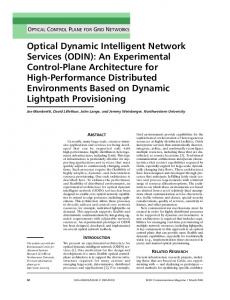
Figure 2: Wide area mobility testbed Figure 2 shows our prototype set up. Three agents are attached to three different networks (LANs). Servers and 802.11 Access Points are connected to FE2 and FE3. Connections to external servers are through FE1. All FEs are controlled by a central controller through a separate management port. Both FE2 and FE3 have a 4-port NetFPGA GigE card, and FE1 has a 3-port GigE card. All machines run Fedora Core 9. In order to support layer 3 routing and IP mobility, the central controller maintains two tables: topology table and address table. Topology table gives the connectivity between FEs. Address table keeps track of locations of each mobile node, i.e., the ID of the FE through which the mobile node is registered. Note that here we do not differentiate between virtual and physical devices. Routing path from each router to each destination is computed based on topology and address information. Once the controller computes the path, it installs the forwarding table on each FE. Table 1 shows an example of the forwarding table on FE2. Note that FE2 needs to modify the data link (MAC) layer destination addresses for packets routed to local nodes. This is because all packets are routed based on IP addresses and the original
6. RELATED WORK Bradford et al. have proposed a solution to migrate VMs across wide-area networks by using dynamic DNS and tunneling [6]. In this approach, VM is assigned a new IP address at the target location. During the transition period, the VM maintains both old and new IP addresses, and packets going to the old address are forwarded from the old hosting machine to the new hosting machine via an IP tunnel. The main limitation is that it is not easy to bound the transition
1 http://openflowswitch.org/downloads/openflow0.8.9 2.tar.gz
2
42
wiki.openvz.org
time. Transition time depends on multiple factors including nature of services running on VMs and IP address caching behavior at client side. Hence the forwarding agent may need to run indefinitely at the old host. This approache may also require VM software modification since most VM migration procedures assume the same IP address. The SoftRouter architecture [16] advocated the separation of control elements and forwarding elements by use of distributed forwarding elements communicating over an open interface with a centralized route controller. A dynamic binding protocol is used to associate forwarding elements with a controller. A centralized route controller approach and its benefits for solving several configuration and BGP related problems was presented in [8]. The 4D architecture [20] pointed out the difficulties in network management due to distributed state and advocated a redistribution of function with more centralized control to enable easier achievement of network-wide management objectives. A centralized controller approach is also used in the Ethane [9] and Openflow [17] systems. In Ethane, the central controller is used to meet stringent security needs for enterprise networks using a default-off paradigm. The Openflow system enables easy experimentation of clean-slate approaches to networking by accomplishing a customizable overlay of Openflow capable systems in existing networks. VICTOR is an adaptation of the SoftRouter and Openflow architectures, applied to solve wide area VM migration issues. The inefficiency of the current mobile IP architecture can be remedied by the mechanisms called route optimization [19]. However, they rely on the modification to the correspondent nodes, which are better to be kept independent and unaware of the node mobility. The other mobility management techniques are all based on the current mobile IP architecture [5]. In [22], a similar architecture as ours called home agent migration is proposed to solve the triangular routing problem, without relying on the concept of distributed virtual router with centralized control plane. There are other attempts to use a common infrastructure to generalize the Internet communication for multicast, anycast, and mobility services. i3 is an overlay-based Internet Indirection Infrastructure that offers a rendezvous-based communication abstraction [21]. SelNet is another example that a virtualized link layer can support explicit indirection [13]. These require changes to the current Internet architecture and are not particularly tailored to the specific needs of VM migration.
7.
path selection at different locations in the network (based on policies, traffic information, utilization, etc). Exploiting this capability in an effective manner remains a topic of future research.
8. REFERENCES [1] mokafive. http://www.mokafive.com. [2] onlive. http://www.onlive.com. [3] Global Environment for Network Innovations. http://www.geni.net, 2006. [4] J. Abley, K. Lindqvist, E. Davies, B. Black, and V. Gill. RFC 4116: IPv4 Multihoming Practices and Limitations. http://www.ietf.org, 2005. [5] I. F. Akyildiz, J. Xie, and S. Mohanty. A Survey of Mobility Management in Next-generation All-IP-based Wireless Systems. IEEE Wireless Communications, Aug. 2004. [6] R. Bradford, E. Kotsovinos, A. Feldmann, and H. Schioberg. Live wide-area migration of virtual machines including local persistent state. In ACM/Usenix International Conference On Virtual Execution Environments, 2007. [7] E. C. Perkins. RFC 3344: IP Mobility Support for IPv4. http://www.ietf.org, 2005. [8] M. Caesar, D. Caldwell, N. Feamster, J. Rexford, A. Shaikh, and J. van der Merwe. Design and Implementation of a Routing Control Platform. In Networked Systems Design and Implementation, 2005. [9] M. Casado, M. J. Freedman, and S. Shenker. Ethane: Taking Control of the Enterprise. In ACM SIGCOMM, 2007. [10] M. A. et al. Above the Clouds: A Berkeley View of Cloud Computing. http://www.eecs.berkeley.edu/Pubs/TechRpts/2009/ EECS-2009-28.pdf, 2009. [11] D. Farinacci, V. Fuller, D. Meyer, and D. Lewis. Locator/ID Separation Protocol (LISP) draft-farinacci-lisp-12.txt. http://tools.ietf.org, 2009. [12] N. Feamster, L. Gao, and J. Rexford. How to Lease the Internet in Your Spare Time. ACM Computer Communication Review, Jan. 2006. [13] R. Gold, P. Gunningberg, and C. Tschudin. A Virtualized Link Layer with Support for Indirection. In ACM SIGCOMM FDNA, 2004. [14] D. Johnson, C. Perkins, and J. Arkko. RFC 3775: Mobility Support in IPv6. http://www.ietf.org, 2004. [15] D. A. Joseph, A. Tavakoli, and I. Stoica. A Policy-aware Switching Layer for Data Centers. In ACM SIGCOMM, 2008. [16] T. Lakshman, T. Nandagopal, R. Ramjee, K. Sabnani, and T. Woo. The SoftRouter Architecture. In ACM HOTNETS, 2004. [17] N. McKeown, T. Anderson, H. Balakrishnan, G. Parulkar, L. Peterson, J. Rexford, S. Shenker, and J. Turner. Openflow: Enabling innovation in campus networks. http://www.openflowswitch.org/wp/documents/, 2008. [18] J. Networks. Logical Router Overview. http://www.juniper.net/techpubs/software/junos/ junos73/swconfig73-routing/html/logical-routeroverview.html.
CONCLUSION
We believe enabling wide-area VM mobility in an efficient manner can be of significant value to many cloud-computing applications. A solution to this problem which builds on SoftRouter and Openflow like approaches with distributed forwarding elements and centralized control was presented. Since VMs used for cloud-computing applications will be hosted in data centers, the focus of this paper has been on VM migration within and between data centers. Several open issues remain for future research particularly the use of this architecture in enabling new applications and in simplifying implementation of current features. An example is implementing policy-based routing or routing to meet traffic engineering needs. For traffic engineering, since all FEs are controlled from a central location, it is possible to coordinate
43
[19] C. E. Perkins and D. B. Johnson. Route Optimization for Mobile IP. Cluster Computing, June 1998. [20] J. Rexford, A. Greenberg, G. Hjalmtysson, D. A. Maltz, A. Myers, G. Xie, J. Zhan, and H. Zhang. Network-Wide Decision Making: Toward a Wafer-Thin Control Plane. In ACM SIGCOMM HotNets Workshop, 2004.
[21] I. Stoica, D. Adkins, S. Zhuang, S. Shenker, and S. Surana. Internet Indirection Infrastructure. In ACM SIGCOMM, 2002. [22] R. Wakikawa, G. Valadon, and J. Murai. Migrating Home Agents Towards Internet-Scale Mobility Deployments. In ACM CoNEXT, 2006.
44