Network Virtualization – a View from the Bottom Jorge Carapinha
Javier Jiménez
PT Inovação Rua Eng. Ferreira Pinto Basto 3810-106 Aveiro Portugal +351 234 403200
Telefónica I+D C/ Emilio Vargas, 6 28043 Madrid Spain +34 913 374 000
[email protected]
[email protected] Internet “ossification” problem and stimulating the development and deployment of new network technologies and advanced applications. In addition, virtualization is expected to provide a clean separation of services and infrastructure and facilitate new ways of doing business by allowing the trading of network resources among multiple providers and customers.
ABSTRACT The interest in network virtualization has been growing steadily among the networking community in the last few years. Network virtualization opens up new possibilities for the evolution path to the Future Internet by enabling the deployment of different architectures and protocols over a shared physical infrastructure. The deployment of network virtualization imposes new requirements and raises new issues in relation to how networks are provisioned, managed and controlled today. The starting point for this paper is the network virtualization reference model conceived in the framework of the EU funded 4WARD project. In this paper we look at network virtualization mainly from the perspective of the network infrastructure provider, following the 4WARD network virtualization architecture and evaluate the main issues and challenges to be faced in commercial operator environments.
Up to now the concept of network virtualization has been explored essentially in testbeds, on a limited scale. Several proposals for network virtualization architecture or for the utilization of network virtualization in several contexts have been put forward [2, 3, 4, 5, 12, 13]. However, so far, the impact of network virtualization on the underlying physical infrastructure has been relatively overlooked. In particular, the feasibility of the network virtualization concept in large scale operator networks has not been adequately assessed. There are multiple challenges associated with the deployment of network virtualization in operator infrastructures. A few examples are how to enforce isolation between different virtual networks, how to conciliate a wide range of requirements of different virtual networks, how to fulfill carrier-class level reliability, how to guarantee scalability. In this paper, we are mainly interested in evaluating the impact of virtualization on the underlying network infrastructure. We use the 4WARD network virtualization architecture as the main reference [1].
Categories and Subject Descriptors C.2.3 [Computer-Communication Architecture and Design
Networks]:
Network
General Terms Design, Management
Keywords Network Virtualization, Resource Management
2. OVERVIEW AND STATE OF THE ART 2.1 From VPNs to VNs
1. INTRODUCTION
In general, virtualization provides an abstraction between user and physical resources, so that the user gets the illusion of direct interaction with those physical resources. In the last few years, significant advances in operating system virtualization technologies have been achieved, with contributions from major players [6, 7, 8, 9], which has enabled the use of virtualization in a growing number of contexts and applications. Major router vendors are also following this trend and it seems likely that network virtualization will become a reality in operator networks in a not too distant future [10, 11].
In the last few years, the concept of network virtualization has attracted a great deal of attention from industry and research fora. Although it is not a strictly new concept, a network virtualization “renaissance” has been originated mainly from the realization that it can provide a platform upon which novel network architectures can be built, experimented and evaluated, freed from legacy technology constraints. Furthermore, network virtualization has been heralded as the keystone of a new global Internet architecture, a new component enabling the coexistence of multiple networking approaches, thus overcoming the present
The concept of network virtualization is not new – it was materialized in the past (albeit in a limited way) with networkbased VPNs1, which have been a highly successful approach to provide separate virtual networks over a common physical infrastructure. One may wonder why full-blown network
Permission to make digital or hard copies of all or part of this work for personal or classroom use is granted without fee provided that copies are not made or distributed for profit or commercial advantage and that copies bear this notice and the full citation on the first page. To copy otherwise, or republish, to post on servers or to redistribute to lists, requires prior specific permission and/or a fee. VISA’09, August 17, 2009, Barcelona, Spain. Copyright 2009 ACM 978-1-60558-595-6/09/08...$10.00.
1
73
In the context of this paper, by VPN we mean a network-based provider provisioned layer 3 Virtual Private Network, of which the BGP/MPLS VPN model [19] is a common example.
dedicated physical router. However, in most cases, a virtual router provides an illusion of isolation, rather than a real isolation, as it lacks dedicated memory, processing and I/O resources.
virtualization is in fact required if the VPN model has been so successful to deploy the concept of virtual network (VN). VPNs fulfill the basic goal of providing different logical networks over a shared infrastructure, but suffer from a few limitations, among others: •
All virtual networks are based on the same technology and protocol stack, which precludes the coexistence of different networking solutions;
•
A real isolation of virtual network resources is not possible, by default;
•
A clean separation of the roles of infrastructure provider and VPN service provider is not possible and in practice they are played by the same entity.
Virtual network 2
Virtual network 1
Network virtualization goes a step further by enabling independent programmability of virtual networks. This means that a virtual network is no longer necessarily based on IP, or any other specific technology, and any kind of network architecture can in principle be built over a virtual network.
Network substrate
Figure 1 - Network virtualization model
Another important strength of virtualization is the native capability to handle multi-provider scenarios and hide the specificities of the network infrastructure, including the existence of multiple administrative domains. Although some workaround solutions exist, this has traditionally been a complicated issue for VPNs.
Node virtualization is based on isolation and partitioning of hardware resources. Physical resources of a substrate node (e.g. CPU, memory, storage capacity, link bandwidth) are partitioned into slices and each slice is allocated to a virtual node according to a set of requirements. Recent developments in operating system virtualization have permitted significant advances in terms of fairness and performance.
Finally, network virtualization provides a real isolation of virtual networks sharing the same infrastructure, for example by means of different operating system instances, and not just an illusory isolation, as provided by VPNs.
Virtualization of substrate nodes, in combination with virtualization of links interconnecting those substrate nodes, enables the creation of virtual networks, functionally equivalent to a physical network.
2.2 Basic components
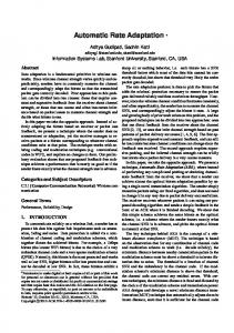
A substrate node terminates one or multiple physical links, which may in turn carry multiple virtual links. Correspondingly, a virtual node terminates one or multiple virtual links. For scalability reasons, virtual links may be handled per aggregate, rather than per virtual link, as will be discussed later on. Some substrate nodes, in addition to terminate virtual links, are also able to forward traffic transported in virtual links in a transparent way (this is the case of node b in Figure 2).
Network virtualization is composed of two main components – link virtualization and node virtualization. Link virtualization allows the transport of multiple separate virtual links over a shared physical link. A virtual link is often identified explicitly by a tag, but can also be identified implicitly, by a time slot or a wavelength, for example. A wide variety of the standard link virtualization techniques available in today’s Internet (e.g. ATM, Ethernet 802.1q, MPLS) may in principle be used for this purpose.
a
c b
The basic elements of network virtualization are shown in Figure 1. At the substrate level, the substrate node is network equipment capable of supporting virtual nodes by means of any virtualization technology. A single substrate node typically contains a number of virtual nodes.
A1
C1
A2
B1
C2
A3
B2
C3
A4
The virtual node is another central element in virtual network architecture. The concept of node virtualization has been materialized, to some extent, by virtual routers2. Although the practical realization of the concept has had a few variations, in broad terms, a virtual router appears for all purposes (e.g. configuration, management, monitoring, troubleshooting) like a
C4 C5
A5 Virtual Physical Virtual Substrate interface link node node
Virtual link
Virtual link aggregate
Figure 2 - Basic network virtualization elements 2
From a functional point of view, substrate nodes can be classified in four major groups, according to the type of functionality that they provide:
In the context of this paper, we prefer the technology-agnostic term virtual node, as any network protocol other than IP should in principle be deployable on a virtual network.
74
•
Edge nodes: located at the edge of the substrate network, these nodes are mainly points of presence (PoP) of the network infrastructure provider. Typically, these edge nodes are connected to end users, either directly or through an access network provider, which may be itself virtualized, or not; geographical location is usually a key attribute of this kind of nodes.
•
Core VN-capable nodes: support virtualization, i.e. can host virtual nodes and can also support non-VN traffic (again, node b in Figure 2). A core VN-capable node may be connected to edge nodes, or to other core nodes, either VN-capable or not.
•
Core transport nodes: do not support node virtualization, are typically core nodes used to transport traffic.
•
Border nodes: are connected to neighbor border nodes located in different network domains.
It should be noted that these functions are not mutually exclusive – for example, node b in Figure 2 supports both core VN-capable node and core transport node functions. Figure 3 shows a scenario with two network domains, A and B, and the four types of network nodes identified above.
•
The virtual network operator (VNO) deploys any protocol stack and network architecture over a VN, independently of the underlying physical network technologies. The VNO operates, maintains, controls and manages the virtual network. Ideally, the fact that resources are virtual, rather than physical, should not imply any major impact from an operational point of view. Thus, the role of the VNO should be indistinguishable from that of any operator running a native network infrastructure. VNOs have a unified view of the network, regardless of the multiple infrastructure domains on which it is built.
3. INCENTIVES TO DEPLOY NETWORK VIRTUALIZATION
Network domain A
Core transport node
The virtual network provider (VNP) is responsible for finding and composing the adequate set of virtual resources from one or more infrastructure providers, in order to fulfill the virtual network operator request. The VNP leases slices of the virtualized infrastructure from one or more InPs and puts them together. Strictly speaking, what the VNP provides is not a network yet, but just an empty container where the virtual network operator builds the protocols that make up the VN.
It should be noted that this model does not preclude the possibility of more than one role being played by a single entity. In a vertically integrated scenario, the three roles are typically played by the same operator. Yet, even in this case, a functional separation of roles should make sense.
Network domain B
Core VNEdge node capable node
•
No matter how interesting the concept of network virtualization may be from a technical point of view, it will only become a reality in commercial environments if there are enough incentives for network providers to build it. Some scenarios in which an infrastructure provider could benefit from implementing network virtualization could be the following: •
Network operators reselling infrastructure to third parties: the service could be conceived as an enhancement of the VPN portfolio, in which the provision of router capacity is added. Nevertheless, networks may be considered as key assets from an operator’s perspective. There might be different pricing expectations from different stakeholders. The development of novel compensation mechanisms will be necessary to ensure that each role finds a place in the value chain.
•
Network operators using virtualization to diversify their own infrastructure for private purposes, or to trusted or corporate third parties (e.g. mobile operator renting a virtual network from the fixed branch): the aim would be to optimize the delivery of multiple isolated services and network architectures over a common, costeffective infrastructure.
•
Network sharing: along with a cost-reduction strategy, network operators are steadily exploring the deployment of common infrastructures (e.g. in emerging or nonstrategic markets) to share capital investments. Network virtualization could be used in this scenario to assure a
Border node
Figure 3 - Types of substrate nodes
2.3 Business roles In general, the 4WARD network virtualization model includes three different business roles: •
The Infrastructure Provider (InP) deploys and runs the network physical resources, and partitions them into isolated virtual slices, using some virtualization technology. Typically, these resources are offered to another service provider, and not to end users (but the InP customer might as well be a corporation using the virtual network for its internal use, rather than to build commercial end user services). The InP has a vision of the resources allocated to each VN, but not of the protocols running inside.
75
particular, the isolation of different virtual networks should be guaranteed in a scalable way.
proper isolation of the different networks while minimizing the total cost of ownership [17]. •
•
Managed services: Some telecom operators are increasingly focusing their growth strategies towards services delivery, customer orientation and product marketing. In this context, a potential approach would be the externalization of infrastructure to better focus on their core service oriented business. A third party (e.g. a system integrator) could in this context become an infrastructure provider, and could therefore benefit from virtualization techniques to better capitalize its investments in new network deployments. The same approach could be followed by governments or public entities aiming at deploying neutral telecom infrastructure, to promote the development of the digital society. However, publicly managed networks have proven to be a difficult task, mainly for political reasons.
Manageability: The InP must have a view of the underlying physical topology, operational state, provisioning status, and other parameters associated with the equipment providing the virtual network.
•
Traffic and network resource control: Traffic engineering and management techniques performed by the InP must not constrain the basic operation of a VN in any way.
•
Isolation: Mechanisms to guarantee deterministic degrees of isolation between virtual networks must be provided. It must be guaranteed that misbehaving VNs (either accidently or purposefully) do not affect the performance of other VNs sharing the same resources (e.g. memory space, storage, bandwidth, processing power), as well as non-VN traffic.
•
Scalability: The number of VNs on a specific network administrative domain may grow to the order of thousands, or more. Any technical solution must be scalable to cope with any number of virtual networks. In
On-demand provisioning: It must be possible to create, modify and remove VNs dynamically at request, with a minimal impact on the underlying infrastructure. The characteristics of a VN may change dynamically at runtime and in many cases a VN will have a limited lifespan.
•
Network technology agnosticism: Network virtualization should not rely or depend on any specific network technology. In particular, multi-domain scenarios across dissimilar infrastructure domains should be possible.
Additionally, in the data plane, identification of virtual links by means of a virtual link ID (VLID) is also required. The most straightforward solution would consist of simply mapping the VLID to whatever data link layer specific tag is in use. A number of available link virtualization techniques, such as ATM, Ethernet VLAN or MPLS, could perfectly be used for this purpose. For example, in the case of MPLS, a different LSP would be allocated to each virtual link. This means that the VLID would be used both as a virtual link identifier and a tag for data forwarding. This apparent simplicity does not come without a cost. On the one hand, for every new virtual link, a new VLID would have to be learned by all network nodes in the data path. Since the number of virtual links has a square law relationship to the number of virtual nodes in the network, this would represent a clear scalability concern. It is clear that large scale scenarios call for a more scalable approach.
In a network virtualization scenario, an InP must fulfill generic network infrastructure provider requirements, as well as new requirements specifically related with virtualization of network resources, as detailed in the following paragraphs.
•
•
As stated before, a VN may span multiple network infrastructure domains. In order to provision and control VNs spanning multiple infrastructure domains, there must be a way to uniquely identify a specific VN on a global scale through a Virtual Network ID (VNID). This can be achieved by concatenating two pieces of information – the identification of the organization responsible for the VN (in principle, the VNO), which is supposed to be globally unique, and the ID allocated by the VNO to the VN, which must be unique within that specific administrative domain [18].
4. DESIGNING VN-ENABLED NETWORKS 4.1 Infrastructure Provider requirements
Robustness: The network should continue to operate in the event of node or link failure. A virtual network should provide carrier-class reliability (typically in the order of 99,99% to 99,999%).
Inter-domain interoperability: In the case of VNs spanning multiple infrastructure provider domains, seamless interoperability must be guaranteed.
4.2 Virtual Network ID, Virtual Link ID, virtual link aggregation and scalability
In a research environment, virtual infrastructure providers could be promoted to permit the validation of emerging Internet architectures. In the long term, this approach could be followed by network operators aiming at providing enhanced peering models (i.e. more than best-effort), with the goal to increase the value for global connectivity services.
•
•
As a matter of fact, scalability is a major requirement for virtual networks. One of the reasons why VPNs, namely those based on the BGP/MPLS model, have been so successful lies in its good scalability properties, which basically result from the clear separation of edge and core functions. Only edge nodes deal with VPNs and support virtualization (or an illusion of it, to be more precise), whereas core nodes are only concerned with forwarding traffic trunks and have no awareness of VPNs whatsoever3. Thus, the growth of the number of VPNs does not have any impact on the network core. 3
76
With the possible exception of BGP route reflectors used to disseminate VPN routes.
For this reason, virtual link aggregation will certainly constitute an important network virtualization requirement in operator networks. A virtual link aggregate can be defined as a set of virtual links that follow a common path and are treated similarly between a pair of virtual nodes. In practice, virtual link aggregation can be performed by carrying at least two types of identifiers in the data plane – one for endpoint VN identification and another for hop-by-hop forwarding, identifying the virtual link aggregate (nodes in the core need to be aware of the latter only). Virtual link aggregation simplifies the job of core substrate nodes (as they only have to deal with a limited number of virtual link aggregates, rather than a potentially high number of individual virtual links), enhances scalability (as the growth of number of VNs does not necessarily imply additional load in the network core nodes) and improves performance.
4.3 QoS and isolation One of the limitations of legacy VPN approaches is that, because the matrix of incoming and outgoing traffic between every possible source-destination pair is impossible to predict, a guaranteed allocation of resources per VPN is usually not possible. On the contrary, VNs allow a fine grained allocation of resources, including bandwidth per virtual link on every segment of the substrate network. However, in practice, a fine grained perVN resource control is not compatible with scalable aggregationbased approaches, described before. Hence, there is a trade-off between scalability (which favors aggregation) and strict VN isolation (which requires control of resources per virtual link). Virtualization raises new QoS issues. More than QoS differentiation, virtualization requires QoS isolation. In all respects, including deterministic performance, a VN should replicate a network supported by physical resources. In a virtualization-based environment, QoS can be handled at two levels:
However, there are a few issues about virtual link aggregation in a network virtualization environment to be noted, so the straight replication of the VPN scenario may not be entirely possible. Figure 4 illustrates link aggregation and its relationship with node virtualization in four different scenarios. Cases 1 and 2 correspond to the legacy VPN scenario. In both cases, only the edge nodes (a and e) support node virtualization in the data path. Virtual link aggregation, used in case 2, allows nodes b, c and d to handle a single virtual link aggregate and ignore individual virtual links, thus executing a much simpler job, compared to case 1. b
c
d
Inside a VN, any QoS mechanism and tool can in principle be defined and deployed by the VNO (for example, different classes of service for voice and data). Intra-VN QoS mechanisms must not be constrained by the characteristics of the substrate (including traffic engineering performed by the InP), or by the traffic running in other VNs sharing the same resources.
•
At the substrate level, QoS isolation between virtual networks is a key requirement, as any QoS policy and mechanism inside the VN cannot be built without adequate guarantees of performance. However, strict QoS isolation of virtual networks requires substrate nodes to apply a per-VN treatment to the traffic. As said before, this may not be possible, or desirable, in all cases, mainly for scalability reasons.
e
Case 3
Case 2
Case 1
a
•
Case 4
In the cases where virtual link aggregation is used, all virtual links inside a given virtual link aggregate get a similar QoS treatment by the substrate nodes. Isolation between virtual links in a common aggregate must be then guaranteed by policing the traffic admitted into each virtual link at the source end point. The substrate nodes in the middle have to make sure that bandwidth is shared between aggregates in a fair way. Figure 4 - Virtual link aggregation scenarios
5. BUILDING VIRTUAL NETWORKS 5.1 The VNP – InP interface
By contrast, in cases 3 and 4, all substrate nodes in the data path support node virtualization. Contrary to the previous situation, the value of virtual link aggregation is in this case much smaller, if not null. In fact, to take advantage of the economies provided by link aggregation, the number of substrate nodes providing virtualization must be minimized. This is illustrated in cases 3 and 4 – link aggregation in case 4 does not provide any advantage compared to case 3. Link aggregation is only effective if a significant number of substrate nodes along the data path perform transport functions only, and not virtualization. This suggests a trade-off between data plane efficiency offered by virtual link aggregation and flexibility offered by node virtualization in the network core.
The VNP/InP interface is a key component of the network virtualization architecture. Through this interface, the VNP is able to request the establishment of a virtual network, the modification of the characteristics of a virtual network, or the removal of a virtual network. In turn, the InP acknowledges the VNP requests and notifies any relevant event (e.g. network error). The VNP is expected to build the virtual network topology and define resource capacity requirements, namely link bandwidth and node computational capability. As discussed before, other characteristics such as geographical location of the edge nodes will be needed in many cases. The information provided by the VNP to the InP must contain a model of the virtual network topology as a graph, with a set a virtual nodes and virtual links and the applicable constraints. Each virtual node and virtual link
77
Table 1 Virtual Network characteristics Network virtualization Parameters components Virtual network
Virtual node
-
Virtual link
-
Virtual network ID Start time of the service Duration of the service Class of service / reliability Preemption level Node ID Physical location Physical node ID / Don’t care Minimum capacity CPU Memory Storage End points (source / destination node IDs) Traffic characteristics Token bucket parameters Reliability level Normal, critical QoS isolation level Guaranteed, statistical
•
VN admission control: the InP verifies the availability of resources to fulfill the request to setup or modify a VN and decides whether or not it can be accepted.
•
Virtual-to-physical resource mapping: the InP identifies the set of possible substrate nodes and links to host the requested virtual network and selects the optimal solution based on a specific criteria.
Finding the optimal mapping between virtual resources and physical resources has some similarities with the traditional MPLS traffic engineering problem of selecting the best path for data traffic through a network domain, based on a set of constraints and performance objectives. In reality, this problem is considerably more complex because node virtualization brings a new dimension – the computational resources of the network nodes. Several theoretical approaches have been proposed to handle this kind of problem [14, 15, 16]. In practice, the mapping of virtual nodes into physical nodes is often constrained by physical location, in which case the selection of the physical node to associate with a specific virtual node is fixed, or limited to a small set of choices. This is the case of edge nodes, or PoPs, which for economical reasons are supposed to be physically close to customers or end-users. Typically, at least one virtual node should be located in each geographic area (e.g. city, region) where the service is to be deployed. On the contrary, for other types of virtual nodes, physical location is not relevant from the VNP point of view – this usually is the case with core nodes (i.e. core VN-capable nodes and core transport nodes, following the terminology presented in Figure 3), without direct connection to end users.
must be characterized by a number of parameters. A tentative list of parameters to characterize virtual networks, nodes, and links is shown in Table I. The VNP is expected to identify (one or multiple) candidate InPs that are able to provide the required physical resources. This selection presupposes a certain level of knowledge by the VNP about the network infrastructure run by each of the candidate InPs. This means that InPs are expected to announce the relevant information (including cost) in order for the VNP to make an informed decision about the resources to acquire to build a new VN. At the very least, the VNP has to be aware of some basic characteristics of the infrastructure: for example, the geographic reach of the infrastructure must be made public – which means that the edge nodes of the InP network (or PoPs) must be externally known. However, the knowledge of the infrastructure internals by VNP is a much more contentious issue. In theory, a continuum of possible scenarios could be defined, ranging from no visibility (except PoPs) to full visibility, depending on the business and trust relationship between VNP and InP. However, in most practical cases, the internals of the network infrastructure are not exposed to the VNP.
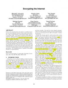
A simple example is shown in Figure 5. The virtual network, as requested by the VNP to the InP, is shown in the upper side of the figure and the bottom part represents the physical infrastructure topology, which accommodates the requested virtual network. F
A B
G
E
D
H
C l
a
In most cases, the mapping of virtual nodes and links into the substrate nodes and links will be performed by the InPs as they are supposed to be able to manage resources and engineer the network according to their own rules, independently of VNPs and VNOs. For example, virtual nodes and links may be physically relocated by the InP without the VNP and VNO even being aware.
F
A
m
b B f c
j
h
G n
D k g d e
5.2 VN admission control and mapping of virtual resources into physical resources
C
i
o
E
Physical link Virtual link
p H
Figure 5 - Mapping virtual resources into physical resources
Once the InP receives a VN setup request from a VNP, two actions must be performed:
The proposed process of mapping virtual resources into physical resources can be divided in two sequential steps:
78
1.
2.
Allocation of edge virtual nodes, which are the points where traffic enters or exits the virtual network, typically constrained by physical location. In the example depicted in Figure 5, the mapping of virtual nodes A, B, C, F, G, H is supposed to be decided based on the geographic location of the respective service points of presence to a, b, e, l, m, p, respectively.
Table 2 Metrics for mapping of virtual resources Metric
Allocation of core virtual nodes. In the example of Figure 5, this corresponds to nodes D and E, which could be mapped, in principle, to any of the substrate nodes f to k. This step is composed of two different but inter-related sub-problems: i.
Selecting the substrate nodes to accommodate the requested virtual nodes;
ii.
Finding the best path to map the virtual links that interconnect the virtual nodes.
Step 1 should be trivial in most cases, but step 2 may be quite complex. There are several possible approaches to handle subproblems i and ii above. A naive approach would consist of handling the two problems in sequence – i.e., first mapping the virtual nodes to physical nodes and, once this is complete, finding the best path for the virtual links. However, the optimal solutions for the two problems are not necessarily coincident.
Applicability
Constraint
Number of virtual nodes
Substrate node
Maximum number of virtual nodes
Available computational resources (e.g. CPU, storage, memory)
Substrate node
Maximum percentage of occupancy of resources (may be different for different types of resources)
Number of virtual links/virtual link aggregates
Physical link
Maximum number of virtual links in the physical link
Available bandwidth
Physical link
Maximum percentage of bandwidth in a physical link allocated to virtual links
the network resources at that moment. However, network state keeps changing as new VNs are setup and others are torn down, or as a result of node or link failure conditions. This often leads to inefficient utilization of resources, in which some parts of the network infrastructure (either link resources or node resources) become excessively loaded while others are under-utilized. Therefore, the capability to reoptimize the allocation of virtual resources across the substrate network without traffic disruption should be a VN requirement.
The selection of the physical nodes to support the requested virtual nodes depends on a number of metrics, as exemplified in Table II. The optimal solution is supposed to result from the proper combination of these metrics. Naturally, different factors may have different weight in the decision. For example, it is quite possible that network node resources constitute a more critical issue than link bandwidth availability. Ultimately, this should be decided based on the specific network characteristics and the policies defined by the network infrastructure operator.
Reoptimization includes the process of finding the optimal path for a flow and, if necessary, rerouting it in a seamless way (i.e. not visible to the VNP or VNO). This process may be performed at request, on a periodic basis or as a result of updated network information. Two kinds of reoptimization can be performed in a network infrastructure supporting virtualization: rerouting of virtual links (keeping virtual nodes unchanged) and reallocation of virtual nodes to different substrate nodes. The first case corresponds to the traditional traffic engineering reoptimization, whereas the second case is a far more complex process, mainly because of the complexity of moving virtual nodes without a noticeable disruption of the service. Again, both kinds of reoptimization are supposed to be carried out by the InP, without any noticeable impact to the VNO.
In the example shown in Figure 5, nodes substrate f and k have been selected out of six possible choices (f, g, h, i, j, k) to host virtual nodes D and E. Even if a specific substrate node is able to offer greater availability of resources, other metrics, such as available link bandwidth may impose a different choice. For any solution, a number of pre-defined constraints must be fulfilled, namely the maximum number of virtual nodes per physical node, the maximum occupancy of node computational resources, the maximum number of virtual links per physical link, the maximum percentage of bandwidth in a physical link that can be allocated to virtual links.
6. CONCLUSION AND FUTURE WORK Network virtualization has been hailed as a key enabler of the evolution to the Future Internet. For network operators, network virtualization also represents a promising tool in several contexts and scenarios: to resell infrastructure to third parties, to diversify infrastructure for private purposes, to minimize the cost of ownership, to provide network infrastructure as a managed service. The business incentives to deploy network virtualization are clear.
VN admission control and the corresponding virtual-to-physical resource mapping are closely intertwined and cannot be separated into independent tasks. Both require an updated knowledge of the load and available resources in the network infrastructure and both are part of the same process. The selection of the network resources to be allocated in reply to a virtual network request has to be decided by the InPs, based on their updated knowledge of the physical resources.
Significant advances and increasing maturity of virtualization technologies have paved the way to the widespread deployment of virtualization in data centers. Bringing virtualization to the core of operator networks seems to be the following step and the materialization of this goal will probably be just a matter of time.
5.3 Network reoptimization When a new virtual network request is received, the InP maps the virtual resources to physical resources taking into account the current state of the network, particularly the level of occupancy of
79
[6] How far will you take that virtual, http://www.microsoft.com/virtualization/default.mspx
Nevertheless, the path to network virtualization is far from trivial. The deployment of services based on network virtualization will not be an easy task and a few daunting issues are to be faced in several aspects, including manageability, scalability and reliability.
[7] Oracle Enterprise Manager Extends Management to Oracle VM, http://www.oracle.com/technologies/virtualization/index.htm l
This paper is focused on the impact of virtualization on the network infrastructure and tries to provide a broad overview of the main challenges ahead. Several topics have been briefly discussed and should be further developed in the future. The problem of finding the optimal solution to map a specific virtual network in a physical substrate has been briefly analyzed. A detailed study of this problem, with a focus on commercial network operator environments, should be carried out in the future. Another issue that should deserve further attention is the coexistence of several crucial, but to some extent conflicting, goals for infrastructure providers: scalability, flexibility, strict VN isolation.
[8] Virtualization, http://www.redhat.com/rhel/virtualization/ [9] Sun Virtualization Solutions, http://www.sun.com/solutions/virtualization/index.jsp [10] Virtualization in the Core of the Network, Juniper White Paper, http://www.juniper.net/us/en/local/pdf/whitepapers/2000299en.pdf [11] Router Virtualization in Service Providers, Cisco White Paper, http://www.cisco.com/en/US/solutions/collateral/ns341/ns52 4/ns562/ns573/white_paper_c11-512753.html
The VPN experience will certainly provide network operators with useful lessons about designing, deploying and operating a VN-enabled network infrastructure. For example, the separation of data forwarding from virtual network awareness is a fundamental enabler of VPN scalability that should make sense in virtual network environments, as well.
[12] Y. Zhu, R. Zhang-Shen, S. Rangarajany, J. Rexford. 2008. Cabernet: Connectivity Architecture for Better Network Services, Proc. Workshop on Rearchitecting the Internet, December 2008. [13] J. Touch, Y. Wang, L. Eggert, G. Finn. 2003. A Virtual Internet Architecture, ACM SIGCOMM Workshop on Future Directions in Network Architecture, Karlsruhe, Germany.
Other areas of future research are reoptimization mechanisms and dynamic reallocation of network resources. Finally, interoperability issues, including VNs spanning across multiple network infrastructure domains and interoperability of different VNs should also be topics for further study.
[14] Y. Zhu, M. Ammar. 2006. Algorithms for Assigning Substrate Network Resources to Virtual Network Components, INFOCOM 2006, Barcelona, Spain.
7. ACKNOWLEDGMENTS
[15] J. Lu, J. Turner. 2006. Efficient Mapping of Virtual Networks onto a Shared Substrate, Technical Report WUCSE-2006-35, Washington University.
The authors are thankful to the members of the 4WARD project, particularly those involved in Work Package 3, for the collaboration and fruitful discussions.
[16] R. Ricci, C. Alfeld, J. Lepreau. 2003. A Solver for the Network Testbed Mapping Problem, SIGCOMM Computer Communications Review, Volume 33, No 2, April 2003.
8. REFERENCES [1] S. Baucke et al. 2009. Virtualization Approach: Concept, 4WARD project Deliverable 3.1.0.
[17] Telefónica and Vodafone Announce Milestone Pan European Collaboration, http://www.vodafone.com/start/media_relations/news/group_ press_releases/2009/telefonica_and_vodafone.html, March 2009.
[2] J. Turner, D. Taylor. 2005. Diversifying the Internet, Proceedings IEEE GLOBECOM 2005. [3] L. Peterson, T. Anderson, D. Culler, and T. Roscoe. 2002. A blueprint for introducing disruptive technology into the Internet, in Proceedings HotNets.
[18] B. Fox, B. Gleeson, 1999, Virtual Private Networks Identifier, IETF RFC2685.
[4] T. Anderson, L. Peterson, S. Shenker, and J. Turner. 2005. Overcoming the Internet impasse through virtualization, IEEE Computer Magazine, vol. 38, pp. 34-41.
[19] E. Rosen, Y. Rekhter. 2006. BGP/MPLS IP Virtual Private Networks (VPNs), IETF RFC 4364.
[5] N. Feamster, L. Gao, J. Rexford. 2006. How to lease the Internet in your spare time, ACM Computer Communication Review, January 2006.
80