Enhancing the Z-width of haptic interfaces through dual-rate sampling Majid H Koul and Subir K Saha
M Manivannan
Mechatronics Lab Department of Mechanical Engineering Indian Institute of Technology Delhi New Delhi - 110016, India
[email protected],
[email protected]
Touch Lab Department of Applied Mechanics Indian Institute of Technology Madras Chennai - 600036, India
[email protected]
Abstract—Conventional controllers used in haptic devices are sampled data systems in which the position and velocity of the device is required to realize a visco-elastic virtual wall interaction. Increasing the sampling rate of the controller improves the stable range of virtual wall stiffness but simultaneously exacerbates the estimated velocity. This inefficient velocity estimation limits the implementation range of virtual damping at higher sampling rates, thereby reducing the dynamic range of stable impedance or Z-width of the haptic controller. A dual-rate sampling scheme is proposed here for such controllers, whereby the position and velocity loop is sampled at different rates. Implications of the proposed scheme on the Z-width of haptic controller on a 1DOF (Degree-of-Freedom) custom haptic device is discussed. Experimental results demonstrate the effectiveness of proposed scheme, particularly at higher sampling rates.
I.
I NTRODUCTION AND BACKGROUND
Haptic systems are sampled data systems that enable physical interaction with virtual environments through force-feedback. Due to the discrete nature of virtual wall implementation, conventional haptic systems are unable to render stiff virtual walls. This limited range of stable virtual environment impedance is governed by many factors such as sampling rate of the controller, encoder quantization, physical damping and Coulomb friction of the device [1], [2], [3]. Colgate and Brown [1] coined the term Z-width as a measure of performance of haptic devices. Z-width represents a region of virtual stiffness and virtual damping values that can be stably implemented on a haptic device. In the experiments of Colgate and Brown [1], it was established that increasing the sampling rate of the controller increased the stable range of virtual wall stiffness, but would simultaneously deteriorate velocity information. It was also established that physical damping contributes positively towards the enhancement of virtual impedance. However, increasing the physical damping decreases the device transparency (a requirement in haptics that free space outside the virtual wall should be felt free). A concept of virtual coupling, that decoupled the haptic control problem from the synthesis of virtual environments was proposed by Adams et al. [4] and Colgate et al. [5]. The idea of virtual coupling enables one to focus on enhancing the stability of haptic controllers without worrying about the design of virtual environment. Various techniques to enhance the Z-width of haptic controllers were thus attempted in [6], [7], [8]. Techniques
that focussed primarily on the sampling rate of the controller were proposed in [9], [10], [11], [12], [13], [14]. In particular, Sevcik et al. [11], Chawda et al. [13], Lee and Lee [14], studied the effect of increasing sampling rates (upto 10kHz) on the stability of haptic controllers. Although works by Sevcik et al. [11] and Chawda et al. [13] resulted in improvements at higher sampling rates, Lee and Lee [14] attributed improvement in stability to the non-linear virtual coupling proposed in [15]. Lee and Lee [14], however did not consider the effect of virtual damping in their analysis. From the authors knowledge, all the techniques reported above used uniform sampling rates for the haptic controller. This demanded better estimation of velocity, specifically at higher sampling rates, which would be possible only by using higher resolution encoders [1], [2] along-with complex velocity estimation techniques as reported in [13]. For a given encoder resolution, improving the Zwidth of a haptic controller remains a challenge. In this work, we propose an idea of dual-rate sampling scheme to improve the Z-width and realize stable contact with stiffer walls. In the proposed scheme, the position and velocity loop is de-coupled. Our proposition is based on the fact that, higher the sampling rates, higher the stable range of virtual wall stiffness. Similarly lower the sampling rates, better is the velocity estimated. The proposed idea of dual-rate sampling within a controller is similar to the concept of up- and down-sampling used in the digital control literature, i.e., multiple sampling rates at different locations of a control loop. This type of multi-rate sampling has been exploited during the last decade in the area of motion control systems [20], [21] and [22]. The scheme has been particularly used for performance enhancement in feed-forward loops, in position tracking control [20] and other motion control applications where the basic sampling rate was constrained for one reason or another [22]. Motivation for such multi-rate schemes has been to make the control input smooth when the measurement sampling rate could not be arbitrarily increased due of the sensor bandwidth or any other hardware constraint [20]. Multi-rate sampling scheme has also been recently used in bilateral tele-operation for acceleration based control [23] and has been particularly recommended for applications incorporating multiple sensors and actuators with different bandwidths [20].
ZOHT2
T2
Xd#
FB
H(s) (Human Impedance)
H(s) (Human Impedance) Fh -
Unilateral Constraint
Fh -
Unilateral Constraint
Fd
D(s) (Device Admittance)
+
Vd
Xd
Fd
D(s) (Device Admittance)
+ FVE
FVE Environment Impedance
ZOHT
Fk
Xd+
T
+
Vd
Xd
Environment Impedance
ZOH1
T1
Xd+
Fk
+ ZOH2
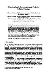
Fig. 1.
T2
Xd#
FB
Conventional haptic controller with uniform-rate sampler T
Our motive here is to discuss and explore the feasibility of using dual-rate sampling in increasing the Z-width of haptic controllers, specifically at higher sampling rates. The rest of the paper is organised as follows: Section 2 discusses the basic components of a haptic controller and details about the proposed dual-rate haptic controller, Section 3 explains the experimental procedure, while results and discussions are detailed in Section 4. Summary along-with future work is provided in Section 5. II.
D UAL - RATE H APTIC C ONTROLLER
In order to explain the concept of our proposed dual-rate sampling scheme, we consider here a simple model of virtual wall interaction with a 1-DOF rotational haptic device. The feedback/ reaction torque τ as a result of motion inside the virtual wall is computed as τ = Kθ + Bω
Fig. 2.
Proposed haptic controller with dual-rate sampling T1 and T2 H(s) (Human Impedance)
Unilateral F is achieved by sampling the position and velocity data at Constraint F different rates. Position data isD(s) sampledV faster Xi.e., at T1 , Admittance) + with the consideration that(Device higher sampling rate improves the stableF range of virtual wall stiffness [1], [3]. Velocity on Environment Impedance the other hand, is ZOH estimated slowly i.e., at T2 with the fact that at higher samplingF rates velocity dataX is Texacerbated. This idea of de-coupled sampling forms the central idea of our work that enables us to increase the sampling rate T1 without worrying for velocity exacerbation. The proposed slower sampling of the velocity loop benefits the process of velocity estimation that utilizes encoder data at sampling rate T2 . Overall an expected improvement in the impedance characteristics of the haptic controller is achieved as would be evident from experiments in the next section. h
d
d
d
VE
T
k
d
+
(1)
where, K and B are the virtual wall stiffness in Nm/rad and the virtual wall damping in Nms/rad respectively and θ, ω are the angular displacement in rad and angular velocity in rad/s of the device inside the virtual wall respectively. In a typical haptics application, the feedback torque τ outside the virtual wall is generally zero. Equation (1) represents an impedance based lumped spring-damper model of the virtual wall. These models are generally preferred for their ease and simplicity in modelling and low computational requirements [16]. In a conventional haptic controller as shown in Fig. 1, the position data Xd from the optical encoders is sampled at a uniform sampling rate T . Optical encoders being the simple, convenient and dynamics free position sensors, are ubiquitously used in haptic devices. The sampled position data X+ d is then fed to the virtual environment block E(z). For the haptic force law in (1), velocity is usually estimated from the sampled position data X+ d using FDM (Finite-DifferenceMethod) followed by appropriate filtering. This uniform-rate scheme causes a net zero-order-hold effect ZOHT at the controller output that is purely a function of sampling rate T . From the stability theory of digital controllers, as the sampling rate T is increased, ZOHT effect is decreased thereby improving the stability of the controller. However, the sampling rate T is often restricted by its negative impact on velocity estimation [1]. In the proposed controller with dual-rate scheme, as shown in Fig. 2, the effect of sampling rate on the position and velocity estimation loop is decoupled. This
Although the use of appropriate filtering techniques enables one to estimate velocity smoothly, at higher sampling rate the velocity can be estimated properly only after increasing the encoder resolution [1]. In addition, at higher sampling rates, filter implementation demands more hardware resources (like increased word length in a fixed point filter) compared to the low sampling rate implementation [17]. We utilized a fixed-point second-order Butter-worth filter for filtering velocity in our experiments. In the following section, experiments with a 1-DOF haptic device are presented. III.
E XPERIMENTS WITH 1-DOF HAPTIC DEVICE
Z-width represents a popular qualitative measure to compare the impedance characteristics of haptic controllers [1], [3], [8], [13]. It is a graphical representation of an area between stable range of virtual stiffness and virtual damping coefficients at a particular sampling rate and external impedance. Wider Z-width is always desired to realize a variety of stable impedance models of the virtual wall [1], [3]. Towards the experimental evaluation of the proposed scheme, a 1-DOF part of a custom 2-DOF haptic device developed in our laboratory [18] was used. Fig. 3 depicts the components/ details of a 1-DOF experimental setup. The device consisted of a 10cm long link that was hinged vertically at one end in order to achieve a planar rotational motion. The device was driven by maxon motor RE-25 with a 1000 cpr (counts per revolution) optical encoder mounted on it. The motor axis and the device hinge were non-collocated.
Initial Position
Fig. 4.
Final Position
User rotating the end-effector from initial to final position
Hinge
Extra mass
Fig. 3.
Experimental Setup
An amplified torque of 10× motor torque was provided to the link using a torque enhancer in a capstan drive arrangement with motor shaft. Although, the majority of our experiments were carried out by involving human operator in the haptic loop, a few experiments were also carried out automated. In automated experiments, a constant external torque outside the wall was generated, rather than involving a human operator. The link attached to the motor, was forced to rotate at a particular velocity until the virtual wall was hit. A 70g extra mass was added at the end-effector of the link to increase the inertial effect during the automated experiments. The link would come to a complete stop for a stable contact and would oscillate at the wall for unstable contact. These experiments although successfully used by [7], [13], do not include human operator in the haptic control loop (since human impedance varies timely). However, this non inclusion of human operator makes it difficult to judge the stability characteristics properly, since human operator is a fundamental part of haptic control loop. We therefore made use of automated experiments only for a few experiments like velocity comparison as would be detailed later. Fig. 4 shows the zoomed view of the device used for experiments, along with the user grasp used. While carrying out the manual experiments, we removed an extra mass that was attached previously at the end-effector. The user was then asked to rotate the end-effector with a finger and thumb grasp as shown in Fig. 4. The initial and final position of the trial is marked with a dotted line in Fig. 4. A virtual wall was defined in the controller at the final position. As the end-effector penetrated virtual wall, an opposing torque calculated according to (1) impeded the users motion. The user was asked to feel the reaction force from the virtual wall. For stable contact, the selection criteria was the absence of visually elicit vibrations or a crisp sound while hitting the virtual wall. Although a human operator can sometimes destabilize a stable virtual wall, the experiments were conducted only after training and familiarising the operator with the setup. A video of the experimental procedure is available online at web.iitd.ac.in/∼saha/todownload/AiR2013 kms videos.rar.
Both the control schemes i.e., dual-rate and uniformrate were implemented on Altera’s Cyclone II FPGA (Field Programmable Gate Array). FPGA’s come up with features like inbuilt resource optimization, high frequency on-board clocks, parallel processing, reconfigurability, complete hardware realization of controller modules etc. [19]. Following modules were realized in our controller: quadrature decoder, position counter, virtual wall, FDM, Butter-worth filter, sample and hold device, force computation, PWM generator. For our Z-width experiments, velocity was estimated by cascading FDM module with a low-pass second-order fixed-point Butter-worth filter. Filter design was carried out using filter-design and analysis-tool (fdatool) in Matlab. In most of the haptics and other feedback control systems [1], [13], a low-pass second order Butter-worth filter is a common choice for attenuating noise at high sampling-rates. For the uniform-rate scheme, an appropriate filter cut-off frequency ‘fc ∼ 10% Nyquist frequency’ for the data sampled at T kHz was used, although a smaller fraction can also be chosen. Since the focus of present work was higher sampling-rate applications, experiments were conducted at sampling-rates T1 > 1kHz. The velocity in the proposed dual-rate scheme was computed from a 2kHz sampled position data with fc = 200Hz. This specification caused a filter delay of 1ms. Reducing the cut-off frequency below 200Hz may sometimes provide a better velocity estimate depending upon the device characteristics, however we restricted ourselves to the above specification to avoid further increase in the filter delay. For example, with fc = 30Hz, a 10ms filter delay would be caused for a 2kHz sampled data. Since the control inputs were fed at higher rates than the rate associated with velocity loop, the velocity for the intervening period was assumed to be equal to the last measured velocity. One could think about some predicting/ estimating techniques to estimate velocity in between the samples also. However that would be needed only when the velocity changes are expected to be at a very high rate, which is usually rare in haptics, as it involves human operator in the control loop. An experiment was initially conducted to study the variation and identify maximum stable range of virtual stiffness K with respect to sampling rate T1 alone, i.e., without any virtual damping. The sampling rate T1 was varied stepwise from 100Hz to 50kHz. For a particular sampling rate T1 , virtual wall stiffness K was increased until the operator would feel the onset of instability. These values of virtual stiffness were noted as the maximum stable stiffness at that particular sampling-rate T1 . As seen from Fig. 5, at T1 >
Extra mass
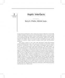
800 T1 = 2kHz, T2 = 2kHz
Virtual Stiffness - K (Nm/rad)
700
T1 = 20kHz, T2 = 20kHZ T1 = 20kHz, T2 = 2kHz
600 500 400 300 200 100 0 0
0.5
1
1.5
2
2.5
3
3.5
Virtual Damping - B (Nmsec/rad)
Sampling rate T1 (kHz) Fig. 6.
Implications on experimental Z-width
Fig. 5. A semi log plot of the maximum value of stable virtual stiffness at sampling rate T1 (with T2 = 0)
20kHz, saturation in the stable values of virtual stiffness was observed i.e., mere increasing the sampling rate of the controller above 20kHz did not improve the stable range of virtual stiffness further. This experiment established the fact that increasing the sampling rate T1 above 20kHz would not in any way benefit towards stability of the controller, rather would unnecessarily burden the controller. We therefore restricted to a maximum sampling rate of T1 = 20kHz in our further experiments. In order to compare the impedance characteristics of the controller with the proposed and conventional schemes, further experiments were conducted at sampling rates T1 = 20, 10 and 2kHz with virtual damping included. For dual-rate scheme, the sampling rate T2 was kept constant at 2kHz, while for uniform-rate scheme T2 was kept equal to T1 . In the following Z-width experiments, at a particular sampling rate T1 and T2 , virtual wall experiments were conducted by increasing the virtual stiffness K gradually for a particular value of virtual damping B. At the onset of instability, the particular value of virtual stiffness was noted. The experiment was repeated five times for each trial in order to assess the average value of K for a particular B. Fig. 6 depicts the experimental Z-width of the controller at different sampling rate combinations. To compare the effect of the proposed scheme over the conventional one, we also plotted the depth of penetration of the end-effector into the virtual wall (in terms of encoder counts). This was done using automated experiments, where we took the advantage of purely uniform external impedance to the virtual wall. Fig. 7 depicts the comparison of depths of penetration at different sampling rate combinations.
IV.
R ESULTS AND D ISCUSSIONS
Fig. 6 depicts the experimental Z-width of the controller for T1 , T2 = 2kHz; T1 , T2 = 20kHz and T1 = 20kHz and T2 = 2kHz. As seen from the figure, for T1 , T2 = 2kHz, the value of stable virtual stiffness increases initially upto 350 Nm/rad compared to the value at B = 0. However, as B
increases, the value of K drops until B = 3.3 Nms/rad. For B > 3.3 Nms/rad, the system was unstable at all values of K. This established the maximum implementation range of B for the velocity computed using T2 = 2kHz. As the sampling rate T1 was increased to 20kHz, the maximum value of virtual stiffness increased to 560 Nm/rad (B = 0). However, as the virtual damping was included, the maximum range of K dropped upto B = 1.7 Nms/rad. After B = 1.7 Nms/rad, the noise in velocity estimation (at T2 ) was considerable, so that the system was unstable for all values of K. These results are similar to those established previously in the conventional literature [1], [3]. For the proposed scheme, however, as seen in Fig. 6, the value of virtual stiffness increased to 780 Nm/rad after including the virtual damping. Also, since velocity in the proposed scheme was estimated at T2 = 2kHz, the implementation range was similar to the one in conventional scheme for T1 , T2 = 2kHz. The maximum achievable stiffness at B = 3.3 Nms/rad was 280 Nm/rad. Fig. 7 depicts the depth of penetration achieved at sampling rates of 10 and 20kHz for the two control schemes. As a matter of fact, for lower values of K, time taken by the device to achieve stable contact with the virtual wall would be larger compared to the one with higher values of K. Hence we took lower range of K for visualising the impact of virtual damping at low velocities. In the above figure, the depth of penetration was plotted only after the first impact of the device end-effector with the virtual wall. From Fig. 7(a), it became quite evident that the depth of penetration was lesser for the dual-rate scheme compared to the uniform-rate scheme. Also the oscillations were relatively damped in the proposed scheme that corresponded to higher virtual wall impedance encountered by the device. An additional contribution from the virtual damping was mainly responsible for relatively low penetration and damped oscillation in the proposed scheme. This however could not be seen in the uniform-rate scheme due to insignificant contribution from virtual damping at low velocity. Similarly at T1 = 10kHz, the depth of penetration inside the virtual wall for three different cases was plotted: dual-rate, uniform-rate and a case without virtual damping. Fig. 7(b) depicts the respective depth of penetration profiles.
250 T1 = T2 = 20 kHz
T2 = 20 kHz
700
200
600 Velocity - (units)
Wall penetration (counts)
T2 = 2kHz
800
T1 = 20 kHz, T2 = 2 kHz
150
100
500 400 300 200
50
100
0 0.4
0.5
0.6
0.7 Time (sec)
0.8
0.9
500
1
600
250
900
1000
1100
200
T1 = 10 kHz, B = 0
180
T1 = 10 kHz, T2 = 2 kHz
T2 = 2kHz T2 = 20 kHz
160
T1 = T2 = 10 kHz
140 Velocity - (units)
Wall penetration (counts)
800 Time (ms)
(a) Velocity for one trial
(a)
200
700
150
100
120 100 80 60 40
50
20 0
0 0.2
0.25
0.3
0.35 0.4 0.45 Time (sec)
0.5
0.55
0.6
950
(b)
1000 1050 Time (ms)
1100
(b) Enlarged view at low velocity
Fig. 7. Relative depth of penetration (encoder counts) inside the virtual wall at K = 32.52 Nm/rad and B = 0.13 Nms/rad
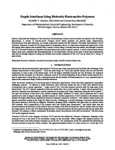
Fig. 8.
Initially some amount of velocity was estimated in case of uniform-rate scheme compared to the case without virtual damping. This resulted into slightly better performance of the uniform-rate scheme compared to the case without virtual damping, where the impedance was merely due to stiffness alone. Since the overall velocity estimation was considerably better in case of the dual-rate scheme i.e., at later stages of impact also, the depth of penetration was lowest and the oscillations were relatively damped.
estimation for various differentiation schemes. They proposed special differentiators for efficiently estimating velocity at higher sampling rates viz. above 10kHz. Although their differentiator performed better at higher sampling rates, their RMS error results confirmed the superiority of using FDM along-with an appropriate filter at sampling rates < 5kHz. The proposed dual-rate scheme therefore does not require the utilization of such complex velocity estimation techniques for T2 = 2kHz while simultaneously increasing T1 above 5kHz.
Fig. 8 depicts the plots of velocity estimated at T2 = 2kHz and T2 = 20kHz using automated experiments. The automated experiment enabled us to identify the velocity profiles at different magnitudes. As seen from Fig. 8(a), the velocity estimated at T2 = 20kHz contains considerable noise compared to the estimation at T2 = 2kHz. Also at later stages of impact as seen in Fig. 8(b), the velocity estimated is considerably poor and nearly has a null value.
The proposed dual-rate scheme therefore achieved a wider Z-width compared to the uniform-rate scheme, since virtual damping is known to improve the stable virtual stiffness of the haptic controller [3]. The proposed method can also be incorporated in a multi-DOF haptic device. For such devices, the feedback/ reaction force from the virtual wall is a function of end-effector position and velocity. The endeffector velocity is typically a function of device Jacobian and its joint rates. These individual joint rates can be efficiently estimated using the proposed dual-rate sampling, thereby contributing to the efficient estimation of end-effector velocity.
For a particular encoder resolution, Chawda et. al [13] compared the root-mean-square (RMS) error in velocity
Velocity output using automated experiment
[5]
We therefore have addressed the issues that arise at higher sampling rates (T > 1kHz), such as the need for high resolution encoders, complex velocity estimation techniques etc. Also the proposed technique is simple to implement and can be easily adapted to the nature of interaction with the virtual wall. A metric can be devised through which the sampling rate for velocity loop could be made adaptive to the nominal speed of the haptic device. For example, for high speed applications, T2 could be greater than 5kHz and for low speeds T2 could be less than 2kHz. The proposed work thus reveals an alternative way to realize improved Z-width of the haptic controller.
[6]
[7]
[8]
[9]
[10]
V.
S UMMARY AND F UTURE W ORK
Stiffer walls are usually realized at higher sampling rates of the haptic controller. However, at higher sampling rates velocity estimation is exacerbated. To stably implement the virtual damping part of the haptic force law, complex velocity estimation techniques along-with higher resolution encoders are needed. A dual-rate sampling scheme for such controllers has been proposed in this work to overcome the limitations in the conventional uniform-rate scheme. The proposed scheme decouples the position and velocity loop of the controller, in other words the position and velocity loops are sampled at faster and slower rates respectively. This scheme leads to a wider Z-width for a given haptic device especially at higher sampling rates. Experiments with the proposed scheme have shown improvements in the impedance characteristics of a 1-DOF custom haptic device. The proposed scheme thus avoids the need for high resolution encoders to efficiently estimate velocity at higher sampling rates. Additional benefits include low computational and resource burden required for velocity filtering at lower sampling rate. As a part of future work, we plan to carry out theoretical stability analysis of the proposed controller. We also plan to conduct experiments involving encoders with different resolutions.
[11]
[12]
[13]
[14]
[15]
[16]
[17]
[18]
ACKNOWLEDGEMENTS
[19]
The authors would like to thank the Department of Science & Technology, Government of India for financial support under the sponsored project SR /S3 /MERC /001 /2008.
[20]
[21]
R EFERENCES [1]
J.E. Colgate, J.M. Brown, “Factors affecting the Z-Width of a haptic display,” Proc: IEEE International Conf. Robotics and Automation, pp. 3205–3210, 1994. [2] J.J. Abbott, A.M. Okamura, “Effects of position quantization and sampling rate on virtual-wall passivity,” IEEE Trans. Robotics, vol. 21(5), pp. 952–964, 2005. [3] J.J. Gil, A. Avello, A. Rubio, J. Florez, “Stability analysis of a 1-DOF haptic interface using the Routh-Hurwitz criterion,” Control Systems Technology, IEEE Trans., vol. 12(4), pp. 583–588, 2004. [4] R. J. Adams, B. Hannaford, “Stable haptic interaction with virtual environments,” IEEE Trans. Robotics and Automation., vol. 15(3), pp. 465–474, 1999.
[22]
[23]
J. E. Colgate, M. C. Stanley, J. M. Brown, “Issues in the haptic display of tool use,” In: Proc. IEEE/RSJ International Conf. Intelligent Robots and Systems, Human Robot Interaction and Cooperative Robots, vol. 3, pp. 140–145, 1995. J. An, D.S. Kwon, “Stability and Performance of Haptic Interfaces with Active/Passive Actuators–Theory and Experiments,” The International Journal of Robotics Research, vol. 25(11), pp. 1121–1136, 2006. D. Weir, J.E. Colgate, M.A. Peshkin, “Measuring and Increasing ZWidth with Active Electrical Damping,”Symposium on Haptic Interfaces for Virtual Environment and Teleoperator Systems, pp. 169–175, 2008. N. Yasrebi, D. Constantinescu, “Extending the Z-Width of a Haptic Device Using Acceleration Feedback,” EuroHaptics 2008 Conference, pp. 157–162, 2008. H. Vasudevan, M.B. Srikanth, M. Manivannan, “Rendering stiffer walls: a hybrid haptic system using continuous and discrete time feedback,” Advanced Robotics, vol. 21, pp. 1323–1338, 2007. B.S. Manohar, H. Vasudevan, M. Manivannan, “DC Motor Damping: Strategies to improve stiffness in virtual environments,” Eurohaptics 2008, Lecture Notes In Computer Science, vol. 502, Proceedings of the 6th international conference on Haptics: Perception, Devices and Scenarios, Madrid, Spain, pp. 53 - 62, 2008. K. S. Sevcik, E. Kopp, M.K O’Malley, “Improved haptic fidelity via reduced sampling period with an FPGA-based real-time hardware platform,” Proc: ASME International Mechanical Engineering Congress Exposition, pp. 1335, 2007. M. Kawai, T. Yoshikawa, “Haptic Display of Movable Virtual Object with Interface Device Capable of Continuous-Time Impedance Display by Analog Circuit,” Proc: IEEE International Conf. Robotics and Automation, pp. 229–234, 2002. V. Chawda, O. Celik, M.K. O’Malley, “Application of Levant’s differentiator for velocity estimation and increased Z-width in haptic interfaces,” Proc: World Haptics Conference (WHC), IEEE, pp. 403–408, 2011. K. Lee, D.Y. Lee, “Multirate control of haptic interface for stability and high fidelity,” Proc: Systems, Man and Cybernetics, IEEE International Conf., vol. 3, pp. 2542–2547, 2004. M.H. Lee, D.Y. Lee, “Stability of haptic interface using nonlinear virtual coupling,” IEEE International Conf. on Systems, Man and Cybernetics, vol. 4, pp. 3420–3424, 2003. J. Kim, S. De, M. A. Srinivasan, “Computationally efficient techniques for real time surgical simulation with force feedback,” In: Proc. 10th Symp. on Haptic Interfaces For Virtual Environment and Teleoperator Systems (HAPTICS02), pp. 51-57, 2002. K. Chapman, P. Hardy, A. Miller, M. George, “CDMA matched filter implementation in Virtex devices,” Xilinx Application Note XAPP212, vo. 1(1), pp. 3–7, 2001. M. Koul, D. Rabinowitz, S.K. Saha, M. Manivannan, “Synthesis and design of a 2-DOF haptic device for simulating epidural injection,” In: Proc. 13th World Congress in Mechanism and Machine Science, Guanajuato, Mexico, pp. 1–7, 2011. E. Monmasson, M.N. Cirstea, “FPGA Design Methodology for Industrial Control SystemsA Review,” IEEE Trans. Industrial Electronics, vol. 54(4), pp. 1824–1842, 2004. M. Tomizuka, “Multi-rate control for motion control applications.” In: The 8th IEEE International Workshop on Advanced Motion Control AMC 04, pp. 21–29, 2004. S. Wu, M. Tomizuka, “Multi-rate Digital Control with Interlacing and Its Application to Hard Disk Drives,” In: Proc. American Control Conference, Denver, pp. 4347–4352, 2003. Y. Gu, M. Tomizuka, “High Performance Tracking Control System Under Measurement Constraints by Multi-Rate Control,” In: Proc. The 14th IFAC World Congress, Beijing, China, pp. 67–71, 1999. H. Tanaka, K. Ohnishi, H. Nishi, “Implementation of multirate acceleration control based bilateral control system including mode transformation on FPGA,” Industrial Electronics, 34th Annual Conference of IEEE, pp. 2465–2470, 2008.