Hindawi Wireless Communications and Mobile Computing Volume 2018, Article ID 3473910, 13 pages https://doi.org/10.1155/2018/3473910
Research Article Enjoy the Benefit of Network Coding: Combat Pollution Attacks in 5G Multihop Networks Jian Li ,1 Tongtong Li,2 Jian Ren,2 and Han-Chieh Chao3,4 1
School of Electronic and Information Engineering, Beijing Jiaotong University, Beijing 100044, China Department of ECE, Michigan State University, East Lansing, MI 48824-1226, USA 3 Department of Electrical Engineering, National Dong Hwa University, Taiwan 4 Institute of Computer Science & Information Engineering and Department of Electronic Engineering, National Ilan University, Taiwan 2
Correspondence should be addressed to Jian Li;
[email protected] Received 27 September 2018; Accepted 15 November 2018; Published 2 December 2018 Guest Editor: Karl Andersson Copyright © 2018 Jian Li et al. This is an open access article distributed under the Creative Commons Attribution License, which permits unrestricted use, distribution, and reproduction in any medium, provided the original work is properly cited. In the upcoming 5G era, many new types of networks will greatly expand the connectivity of the world such as vehicular ad hoc networks (VANETs), Internet of Things (IoT), and device-to-device communications (D2D). Network coding is a promising technology that can significantly improve the throughput and robustness of these emerging 5G multihop networks. However, network coding is generally very fragile to malicious attacks such as message content corruption and node compromise attacks. To take advantage of network coding in performance gain while refraining malicious network attacks is an interesting and challenging research issue. In this paper, we propose a new error-detection and error-correction (EDEC) scheme that can jointly detect and remove the malicious attacks based on the underlying error-control scheme for general multihop networks that can model the 5G multihop networks. The proposed scheme can increase the throughput for network with pollution attacks compared to existing error-detection based schemes. Then we propose a low-density parity check (LDPC) decoding based EDEC (LEDEC) scheme. Our theoretical analysis demonstrates that the LEDEC scheme can further increase the throughput for heavily polluted network environments. We also provide extensive performance evaluation and simulation results to validate the proposed schemes. This research ensures the expected performance gain for the application of network coding in the 5G network under malicious pollution attacks.
1. Introduction Most of the newly emerging networks in the 5G communication network can be modeled using multihop networks, including vehicular ad hoc networks (VANETs), Internet of Things (IoT), and device-to-device communications (D2D). New computing frameworks in the 5G network such as fog computing [1] can also be categorized into multihop networks. The network throughput and robustness could be improved when network coding is utilized. Many researchers have proposed to adopt network coding in the upcoming 5G network, such as in [2–4]. The core notation of network coding is that it allows the participating nodes to encode incoming packets at intermediate network nodes in a way that when a sink receives the packets, it can recover the original
message. Network coding provides a trade-off between maximum multicast flow rate and computational complexity. Network coding was first introduced in the seminal paper by Ahlswede et al. [5]. Li et al. [6] formulated the multicast problem in network coding as the max-flow from the source to each receiving node. They proved that linear coding is sufficient to achieve the optimum. This work made network coding simpler and more practical. Koetter and Medard [7] have shown that linear codes are sufficient to achieve the multicast capacity by coding on a large enough field. Ho et al. [8] have shown that using of random linear network coding is a more practical way to design linear codes. Gkantsidis and Rodriguez [9] have applied the principles of random network coding to the context of peer-to-peer (P2P) content distribution and have shown that file downloading times
2
Wireless Communications and Mobile Computing
can be reduced. Esmaeilzadeh et al. [10] proposed to use feedback-free random linear network coding in broadcasting layered video streams over heterogeneous single-hop wireless networks. Wu et al. [2] designed an efficient data dissemination protocol for VANETs using network coding. Lei et al. [3] applied network coding in Named Data Networking (NDN) in the 5G IoT network and improved the content delivery efficiency. Chi et al. [4] proposed to jointly utilize D2D communication and network coding to achieve high communication reliability in the ultra-dense 5G cell deployment. However, in the context of network coding, all participating nodes must encode the incoming packets according to a fixed coding algorithm. If a packet from an intermediate relay node is corrupted or being tampered, the entire communication may be disrupted. The main purpose of this paper is to develop schemes that can combat network pollution and malicious attacks from the network nodes based on error-control coding in multihop networks. We propose a new scheme that combines errordetection and error-correcting (EDEC) to combat network pollution attacks. In our scheme, the original message symbol is first encoded using an error-control code before encoded by network coding and transmitted. The application of errorcontrol code gives intermediate nodes the capability to detect possible errors or pollution of the message. Unlike the existing schemes, when an intermediate node detects an error, the packet will continue to be forwarded. As long as the errors are correctable, the sink nodes will be able to recover the corrupted packets and decode the original packet symbols. Then we further extend the EDEC scheme and propose LDPC based EDEC (LEDEC) scheme. In the LEDEC scheme we treat the packets as LDPC codewords at the sink nodes and use the belief propagation algorithm (BPA) to decode the LDPC code. It can guarantee a certain network throughput even for a heavily polluted network environment, while the throughput becomes very low for error-detection based schemes. Moreover, we mainly focus on the throughput impact brought by different strategies (discard versus keep) towards corrupted packets. The major contributions of this paper are the following: (i) We propose an EDEC scheme by combining a modified error-control code and network coding. The proposed EDEC scheme can increase the throughput for network environment with pollution attacks compared to existing error-detection based schemes. (ii) We propose the LEDEC scheme by augmenting the EDEC scheme with the LDPC decoding. The proposed LEDEC can further improve the throughput even for network environment with heavy pollution. (iii) We conduct extensive simulations to evaluate the performance of the proposed schemes and demonstrate the advantage of the proposed schemes. The rest of this paper is organized as follows: Section 2 presents the related work. Preliminaries for network coding, error-control coding and the proposed modified errorcontrol code are discussed in Section 3. Adversary model
is also presented in Section 3. The EDEC scheme and performance analysis are described in Section 4. Section 5 presents the LDPC decoding and analysis of the LEDEC scheme. We conclude in Section 6.
2. Related Work Existing work on pollution elimination can largely be divided into error-detection based schemes and error-correction based schemes. For error-detection based schemes, the errors are normally detected at the intermediate forward nodes. For error-correction based schemes, the errors are generally corrected at the sink node. While the error-correction based schemes seem to be more appealing, the computational complexity for encoding and decoding is relatively high [11]. These schemes are generally designed based on knowledge of the network topology, which makes these schemes less flexible to the current networks. Jaggi et al. [12] introduced the first polynomialtime rate-optimal network codes to correct the errors brought by malicious nodes. They also gave the theoretical network capacity with the existence of malicious nodes. However, the communication overhead of the scheme is significant. In [13], the authors proposed a network error-correcting code that combines the nonlinear coding at the source node and linear coding at the intermediate nodes. The code can achieve higher transmission rate than linear network error-correcting codes with exponential encoding and decoding complexity. The limitations of error-correction based schemes make error-detection attractive in some network scenarios. Krohn et al. [14] proposed to use homomorphic hash functions to guarantee correctness of the network flow. The main idea is that each intermediate node will check the correctness of the packets through homomorphic hash functions. If a packet fails the correctness check at an intermediate node, it will be discarded. This approach can reduce the communication overhead and can be used in random network coding. However, the computational complexity is still very high. When the network scale is large, computing too many hash values will also create high delay. Boneh et al. [15] provided cryptographic protection against pollution attacks by authenticating linear subspaces in network coding, which incurs less computation delay than [14]. Shang et al. [16] proposed new homomorphic signature schemes for generation-based network coding. In [17–20], homomorphic message authentication codes (MAC) were designed to detect polluted packets. Yu et al. [17] applied multiple MACs to each packet in secure XOR network coding to filter out polluted packets. Agrawal et al. [18] also designed a homomorphic MAC to check the integrity of network coded data with less computational overhead. Li et al. [19] proposed to use a symmetric key based homomorphic MAC algorithms to detect corrupted packets. In [21], the authors analyzed and improved two homomorphic authentication schemes homomorphic subspace signature (HSS) [22] and key predistribution-based tag encoding (KEPTE) [23] for network coding. To further reduce computational and communication overhead, Kehdi et al. [24] developed a simple error-detection
Wireless Communications and Mobile Computing based Null Key scheme. Their idea is to partition the 𝑛dimensional linear space over 𝐺𝐹(𝑞𝑛 ) into two orthogonal subspaces of dimension 𝑘 (symbol subspace) and 𝑛 − 𝑘 (null key space). Comparing to the homomorphic hash function, the null key scheme is more efficient and has virtually no message delay. Newell et al. [25] improved the work of [24] by splitting the null key into one large constant portion and another small periodically updated portion, making it more suitable for network coding in wireless environments. For all these error-detection based schemes, corrupted packets will be discarded. In packetized networks, a large message is divided into small packets. If a malicious node is able to continuously corrupt even a small fragment (packet) of the message, this fragment will be discarded. As a result, the whole message will be corrupted and the effective throughput will become lower and even close to zero in extreme situations. In our previous work [26], we proposed to keep the corrupted packets instead of dropping them; thus we could decode the corrupted packets in the intermediate forwarding nodes based on the subspace properties. In this paper we further generalize the idea and combine both error-detection and error-correction to guarantee a high throughput even for heavily polluted network environment. It is worth noting here that the authors in [27] proposed using a cooperative nonparametric statistical framework (COPS) for misbehavior mitigation in network coding. Their framework does not need the knowledge of the data packet contents and provides another possible way to combat the network pollution attacks.
3. Preliminaries In this section, we will first introduce basic concepts and notations of network coding. Then we will present the preliminary for error-control code and our proposed modified error-control code, which is the base of our proposed schemes. At last we will present our adversarial model adopted in this paper. 3.1. Network Coding. The main idea of network coding can be illustrated through the butterfly graph [6] in Figure 1. Assume the capacity of all the edges is 𝐶; the capacity of this network is 2𝐶 according to the max-flow min-cut theorem. Only by encoding the incoming bits 𝑥1 , 𝑥2 at node 3, this network can achieve the maximum capacity. In this paper, we adopt the notations of [7]. A network is equivalent to a directed graph 𝐺 = (𝑉, 𝐸), where 𝑉 represents the set of vertices corresponding to the network nodes and 𝐸 represents all the directed edges between vertices corresponding to the communication link. The start vertex V of an edge 𝑒 is called the tail of 𝑒 and written as V = 𝑡𝑎𝑖𝑙(𝑒), while the end vertex 𝑢 of an edge 𝑒 is called the head of of 𝑒 and written as 𝑢 = ℎ𝑒𝑎𝑑(𝑒). For a source node 𝑢, there is a set of symbols X(𝑢) = (x1 , . . . , x𝑙 ) to be sent, where x𝑖 ∈ 𝐺𝐹(2𝑛 ), 1 ≤ 𝑖 ≤ 𝑙. For a link 𝑒 between relay nodes 𝑟1 and 𝑟2 , written as 𝑒 = (𝑟1 , 𝑟2 ), the symbol y𝑒 transmitted on it is the function of all the y𝑒 such that ℎ𝑒𝑎𝑑(𝑒 ) = 𝑟1 . And 𝑦𝑒 can be written as
3 R1
1 R1
R1
R1 +R2 R1 +R2 3
R2
4 R1 +R2
R2 2
R2
Source node Sink node Relay node
Figure 1: A simple example of network coding.
x1 [x ] 𝑙 [ 2] [ ] y𝑒 = ∑ 𝛽𝑒 ,𝑒 ⋅ y𝑒 = ∑𝛽𝑒,𝑖 x𝑖 = 𝛽𝑒 [ . ] , [.] 𝑖=1 𝑒 :ℎ𝑒𝑎𝑑(𝑒)=𝑟1 [.]
(1)
[ x𝑙 ] where 𝛽𝑒 ,𝑒 ∈ 𝐺𝐹(2) is the local network encoding coefficient, 𝛽𝑒,𝑖 ∈ 𝐺𝐹(2) is the global network encoding coefficient for symbol y𝑒 , and 𝛽𝑒 = [𝛽𝑒,1 , 𝛽𝑒,2 , . . . , 𝛽𝑒,𝑙 ] is the network encoding vector. For a sink node V, there is a set of incoming symbols y1 , . . . , y𝑚 from 𝑒 where 𝑡𝑎𝑖𝑙(𝑒 ) = V to be decoded. For network coding to achieve the expected benefits, all the participating nodes in the network should be free of network pollution and malicious attacks. Suppose, under the linear network coding, the sink node receives 𝑚 packet symbols y1 , . . . , y𝑚 . It decodes the original message symbols x1 , . . . , x𝑙 by solving a set of linear equations: x1 x1 𝛽11 . . . 𝛽1𝑙 y1 𝛽1 [ 𝛽 ] [x ] [ 𝛽 . . . 𝛽 ] [x ] [ y ] [ ] [ 2 ] [ 2 ] [ 21 2𝑙 ] [ 2 ] ][ ] [ 2] [ ][ ] [ = [ ] ] ]. [ . ][ . ] = [ . . ][ . ] [ [ . ] [ . ][ . ] [ . [ . ] [ . ] [ . d .. ] [ .. ] [ .. ] [𝛽𝑚 ] [ x𝑙 ]
[𝛽𝑚1 . . . 𝛽𝑚𝑙 ] [ x𝑙 ]
(2)
[y𝑚 ]
For clarity purpose, we number the network coding vectors 𝛽𝑒 received in the sink node from 1 to 𝑚. If all the relay nodes encode correctly and 𝑚 ≥ 𝑙, the sink node can decode all the message symbols successfully. 3.2. Error-Control Coding 3.2.1. Error-Detection. Suppose the original message symbols are in the 𝑘-dimensional linear space over 𝐺𝐹(2𝑘 ). After we encode the symbols using the 𝑘 × 𝑛 generating matrix G of an (𝑛, 𝑘) block code, the encoded codewords will form a linear subspace over 𝐺𝐹(2𝑛 ) of dimension 𝑘. So there will be another 𝑛 − 𝑘 dimensional subspace over the 𝑛 dimensional space, which is orthogonal to the codewords subspace. Denote a
4
Wireless Communications and Mobile Computing
valid codeword by c and the bases for the 𝑛 − 𝑘 dimensional subspace by h1 , . . . , h𝑛−𝑘 ; we have < c, h𝑖 >= 0, 1 ≤ 𝑖 ≤ 𝑛 − 𝑘, where < ⋅, ⋅ > represents the inner product. Let (𝑛 − 𝑘) × 𝑛 matrix H = [h𝑇1, . . . , h𝑇𝑛−𝑘 ]𝑇; H forms a parity check matrix of the codewords and satisfies c ⋅ H𝑇 = 0.
(3)
Suppose r = c+e is a received codeword, where e is an 𝑛-tuple error generated by a malicious node. For the received word r, we can get the syndrome of error pattern e as follows: s = r ⋅ H𝑇 = (c + e) ⋅ H𝑇 = c ⋅ H𝑇 + e ⋅ H𝑇 = e ⋅ H𝑇 .
(4)
For a received codeword r, there are two cases: (i) e equals to a legitimate codeword generated by G. In this case, although r contains error, the error is undetectable using conventional error-control coding techniques; (ii) e contains a nonzero projection to the orthogonal parity check subspace, which satisfies r ⋅ H𝑇 ≠ 0. In this case, we can detect that the received word contains error. In network coding, suppose c𝑗 ’s are a set of valid codewords, c = ∑𝑗 𝛽𝑗 c𝑗 is a linear combination of these codewords, where 𝛽𝑗 is the network encoding coefficient. It can be easily verified that for 1 ≤ 𝑖 ≤ 𝑛 − 𝑘, c ⋅ h𝑇𝑖 = ∑𝛽𝑗 c𝑗 ⋅ h𝑇𝑖 = 0. 𝑗
(5)
Equation (5) ensures that we can still check the correctness of packet symbols using row vectors of H after they are encoded by network coding. Similar to [24], we call the row vectors h𝑖 , 1 ≤ 𝑖 ≤ 𝑛 − 𝑘 null keys. 3.2.2. Error-Correction. From (4), it is clear that r is a codeword if and only if s = 0. The task of maximum likelihood decoding is to find the minimum weight error pattern e such that r ⋅ H𝑇 = e ⋅ H𝑇. In this case, the received r is corrected to r + e = c. In linear network coding, although the packet symbols are not the original ones sent from source nodes, we can still perform error-correction using (4). Suppose r1 , . . . , r𝑖 are received codewords from 𝑖 incoming edges; e is the error vector added to the network encoding r = ∑𝑗 𝛽𝑗 r𝑗 and r = r + e. If the error is within the correction capability of the error-control code, the syndrome will still be r ⋅ H𝑇 = e ⋅ H𝑇 + ∑𝑗 𝛽𝑗 r𝑗 ⋅ H𝑇 = e ⋅ H𝑇 + 0 = e ⋅ H𝑇 . Thus we can correct the error using syndrome decoding. The error-detection and error-correction capabilities are determined by the (𝑛, 𝑘) code structure. Based on the pollution levels of the network, we can select the error-control codes accordingly base on the following proposition. Proposition 1 (see [28]). For an (𝑛, 𝑘) block code with the minimum distance 𝐷, it can detect all the 𝐷 − 1 or less errors, or it can correct all the ⌊(𝐷 − 1)/2⌋ or less errors. In our proposed schemes, the corrupted packets detected at the intermediate nodes will not be discarded. Both the
Distance < (d-1)/2 Wrong Codeword Decode wrong
Distance = d
Received Codeword Decode right Right Codeword
Distance > (d-1)/2 Received Codeword
Figure 2: Limitations of error-control codes.
intact and corrupted packets will be gathered by the sink nodes. The sink nodes can correct the corrupted packets and have a higher communication throughput than the errordetection based schemes. 3.3. Modified Error-Control Code. The error-detection based schemes mainly focus on detecting the corrupt packets. As mentioned in Section 2, when a corrupt packet is detected, it will be discarded. So if an adversary continues to corrupt certain packets, these packets will be continuously dropped and the communication may never succeed. In this paper we try to utilize the corrupted packets to improve the throughput in these situations. To achieve this goal, we need to propose a modified error-control code. 3.3.1. Limitations of Conventional Error-Control Code. A linear error-correcting code encodes the original 𝑘 bits message symbol m to an 𝑛 bits codeword c using a 𝑘 × 𝑛 generating matrix G. Suppose the minimum distance is 𝐷, according to the results in Section 3.2.2, the maximum number of errors we can correct is ⌊(𝐷 − 1)/2⌋. If the number of errors is more than this amount, we may correct the corrupted codeword into a false one, as illustrated in Figure 2. 3.3.2. Proposed Error-Control Code That Can Detect Erroneous Decodings. The conventional error-control code may have undetected decoding errors. This is an inherent nature. No matter how low we set the code rate, these undetected errors may still exist. The decoding errors can only be detected using mechanisms other than a stand-alone error-correcting code. Therefore, we propose to apply modified error-control code to both message symbols and network coding coefficients in (1). In this section, we will use the message symbol as an example. The original message symbol m is first mapped to a 𝑡 bit value h using homomorphic hashes. Then h will be appended to m to form a new 𝑘 + 𝑡 bits message symbol. By encoding this new message symbol we can get the final codeword. So the code becomes an (𝑛, 𝑘 + 𝑡) code. By adding the extra bits, we can mitigate limitations of the conventional error-control code. Figure 3 illustrates the modified encoding scheme. At the sink nodes, the decoded symbol is first split into two parts m and h after the decoding as shown in Figure 4. Then we calculate the mapping h from m . If h
Wireless Communications and Mobile Computing
New message symbol, k+t bits
map
Encode to n bits
successful probability of forging a valid symbol for n=3232, k=3072, b=3, s=40 1 (n,k+t) code
Send
t bits appendix
Figure 3: The encoding process of modified error-control code in EDEC scheme. Decode Received to k+t bits codeword
k+t bits symbol
Split
t bits appendix
Split t bits k bits message map symbol appendix
Compare ?
Figure 4: The decoding process of modified error-control code in EDEC scheme.
and h are different, we can detect a decoding error. Our modification is equivalent to choose 2𝑘 message symbols from 2𝑘+𝑡 symbols. Other message symbols in the 2𝑘+𝑡 symbol space are considered to be illegal. Because the decoding algorithm only guarantees that the decoded codeword is in the 𝑘 + 𝑡 dimensional subspace, the decoded codeword belonging to the 2𝑘+𝑡 − 2𝑘 symbol space implies that the decoding contains error. Theorem 2. Suppose a decoding error occurs, the wrong codeword will be any codeword in the 2𝑘+𝑡 symbol space. So the probability of detecting an erroneous decoding is 𝑝=
2
𝑘
𝑡
−2 2 −1 1 = = 1 − 𝑡. 2𝑡 2 2𝑘+𝑡
0.8 0.6
X: 6 Y: 0.5008
0.4 0.2 0
0
10
20 30 40 50 no. of errors (1's) in a bogus symbol
60
Figure 5: Probability for a forged symbol to pass the check.
Comparing Results: Equal: Right decoding Unequal: Wrong decoding
𝑘+𝑡
probability of passing the check
Original message symbol, k bits
5
(6)
Through properly choosing the parameters 𝑘, 𝑡, we can detect erroneous decodings with little additional overhead. 3.4. Adversary Model. In network coding, a small error injected into an intermediate relay node may diffuse to many packets at the sink node, which will incur errors in the message symbols after the solving of (2). This can cause a significant waste of network resources and sometimes can even ruin the whole network communication. This kind of attack is called pollution attack. In this paper, we assume that the malicious node can inject bogus packets into the network. If the succeeding relay nodes do not detect the bogus packets and produce network coded packets using the bogus packets, we call these packets corrupted packets. The malicious nodes try to forge legitimate packets that can pass the check in (5). In error-detection based schemes that use null keys to check the validity of packet symbols, the source node will randomly distribute 𝑠 null keys in each intermediate relay node for packet checking. The malicious node can increase its successful attack probability by producing bogus symbols orthogonal to the space spanned by the 𝑠 null keys it receives.
When the size of the generating matrix is large, we will use sparse matrices G and H to reduce the encoding and decoding complexity. Suppose there are 𝑏 1’s in each row and in each G ] for 𝑏 ≪ 𝑛, we have the column on average in matrix F = [ H following theorem. Theorem 3. The probability 𝑝𝑚 that a malicious node successfully forges a valid symbol is 𝑝𝑚 =
𝑘 ) ( 𝑏𝑤 , ( 𝑛−𝑠 𝑏𝑤 )
(7)
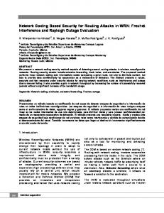
where ( 𝑛𝑘 ) is the number of 𝑘-combinations from a set of 𝑛 elements and 𝑤 ≪ 𝑛 is the number of 1’s in a bogus symbol. Proof (sketch). When the number of errors, which are 1’s in the bogus symbol, is small compared to 𝑛, for each error bit with index 𝑖 there will be 𝑏 distinct vectors with 1’s at the index 𝑖 in F. The bogus symbol will be linear dependent with these 𝑏 vectors with high probability. Thus a bogus symbol with 𝑤 errors (𝑤 ≪ 𝑛) will be linear dependent with at most 𝑏𝑤 vectors, which may include rows from both matrices G and H. When a malicious node forges a symbol which is only linear dependent with the row vectors in G, it will successfully forge a valid symbol. Since the malicious node does not know the row vectors of the matrices G and H except for the null key vectors it has, these row vectors can be viewed as random to the malicious node. The successfully probability is the number of ways of choosing 𝑏𝑤 vectors in all the row vectors of G divided by that of choosing 𝑏𝑤 vectors in all the row vectors of F excluding the 𝑠 null key vectors the malicious node has already known. For large 𝑛, 𝑘, the malicious node has to make 𝑤 small to achieve a high probability 𝑝𝑚 . In a typical parameter setting with 𝑛 = 3232, 𝑘 = 3072, 𝑏 = 3, 𝑠 = 40, each intermediate node will receive 40 null keys randomly selected from 160 null keys. The successful probability of forging a valid symbol is shown in Figure 5. From the figure we can see that to achieve successful probability 𝑝𝑚 = 0.5, the malicious node
6
Wireless Communications and Mobile Computing
Original message symbols Dimension = k Source Node Coded message symbols Dimension = n Encode with (n, k+t) modified error control code
Relay network applying network coding
Figure 6: Apply error-control codes in linear network coding.
can only add 6 errors into a forged symbol, which are easily correctable by the (3232, 3072) code with minimum distance 𝐷 = 161. Thus for the malicious node, in order to produce bogus symbols that can pass the check, it will forge symbols with a small number of errors (1’s) and orthogonal to the null key vectors it has. For the error-control code used to detect the bogus symbols, the errors within the bogus symbols are correctable. However, in the error-detection based schemes that do not perform error-correcting, the bogus symbols that pass the intermediate check will result in a failure of decoding the original message symbols at sink nodes.
4. Proposed EDEC Scheme and Evaluation Similar to the null key scheme, our approach also utilizes the orthogonal space properties of the error-control code, but we use both the error-detection and error-correction techniques. The source node will encode the original message symbols using the modified error-control code prior to message transmission as shown in Figure 6. The properties of the error-control code keep unchanged during the linear network coding. When a corrupted packet is detected, instead of dropping it, we forward it to the sink nodes so that the packet can be used along with other packets to recover the original messages. However, the corrupted packet will not participate in network coding in the subsequent relay nodes once it is detected to be corrupted. The sink node can make use of the corrupted packets according to the decoding results of the modified error-control code in Section 3.3. 4.1. The Proposed EDEC Scheme. The proposed EDEC scheme is divided into two phases: initialization phase and transmission phase. The initialization phase is for null key and security parameter distribution while packet symbols are transmitted through network coding in the transmission phase. 4.1.1. Initialization Phase. In the initialization phase, the source node will first distribute 𝑠 row vectors of the parity check matrix orthogonal to G in Algorithm 1 (null keys) to each of the relay nodes through a secret transmission protocol. Unlike normal linear network coding in which the network encoding vectors are attached to the start or the end of the packets, we propose to distribute the encoded encoding vectors to predetermined secret locations in the packets. The source node will send the location information to all
the sink nodes during the initialization phase through the secure transmission protocol. This will prevent the malicious nodes from corrupting the encoding vector, which is essential for the data decoding. Moreover, the source node will also send the encoding matrix G𝑐 for network encoding vectors and G for packet symbols to all the sink nodes. Once the initialization phase is done, the source nodes can multicast any number of packets to sink nodes. The overhead of the initialization phase is negligible. 4.1.2. Transmission Phase. In the transmission phase, the source node, relay nodes, and sink nodes will perform the proposed EDEC scheme according to Algorithms 1, 2, and 3. In Algorithm 1, the source node will encode the network encoding vector 𝛽𝑖 using the modified error-control code with a much longer appendix and a much lower code rate, compared to the encoding of packet symbols. This can improve the error resistance and detection probability for erroneous decodings to guarantee the correctness of the network encoding vectors used for data decoding. Since there is only one network encoding vector in each packet, the overhead brought by this higher security level is negligible. Algorithm 2 presents the EDEC algorithm for relay nodes. Since the null key vectors are already distributed in the initialization phase, the relay nodes can check whether a packet is intact. Algorithm 3 presents the EDEC algorithm for sink nodes. Since a sink node has already received the encoding matrix G𝑐 and G in Algorithm 1 in the initialization phase, it can perform the error-control code decoding and detect the erroneous decodings. When collecting enough intact packets, it can derive the original data symbols through the decoding of network code. 4.2. Simulation Results of EDEC Scheme. In this section, we first present the simulation platform for EDEC scheme. Then we will compare the EDEC scheme and the error-detection based schemes, which are represented by the null key scheme in the simulation. 4.2.1. Simulation Platform. We simulate the EDEC scheme using ns-2. The scenario is set as a grid network with one source node, a number of relay nodes, and sink nodes. All the nodes are set as wireless nodes using wireless physical layer and 802.11 MAC protocol. The wireless channel is set to TwoRayGround. Once a node receives a packet, it will start the corresponding operations depending on its type (source, relay, malicious, and sink) and the packet content. Figure 7 shows the topology of the simulated network. The source node is located at the lower left corner and 13 sink nodes lie at the upper right. The rest of the nodes are all intermediate nodes that can relay packets. In the simulation, we randomly choose a number of intermediate nodes as malicious nodes to perform pollution attacks. These nodes try to send out bogus packets that can pass the intermediate check as described in Section 3.4 to pollute the network. We can change the number of malicious nodes to evaluate performance of the algorithms under different network conditions. The percentage of malicious nodes is
Wireless Communications and Mobile Computing
7
(1) for packet i do (2) //Encode network encoding vector 𝛽𝑖 in equation (1) using the modified error-control code (Figure 3) (3) h𝑐 ← map(𝛽𝑖 ) (4) u𝑐 ← (𝛽𝑖 | h𝑐 ) (5) Encoded network encoding vector ← u𝑐 ⋅ G𝑐 (6) Distribute the encoded network encoding vector into predetermined locations of the packet (7) for every symbol m of the packet do (8) //Encode m using the modified error-control code (Figure 3) (9) h ← map(m) (10) u ← (m | h) (11) Encoded symbol ← u ⋅ G (12) end for (13) Send out the encoded symbols (14) end for Algorithm 1: EDEC algorithm for source nodes.
(1) if every symbol in the received packet is intact then (2) if 𝑥 (a predetermined number) packets received then (3) Generate 𝑥 randomly, linearly combined packets using the received packets (network coding) (4) Send out the network encoded packets (5) end if (6) else (7) Mark the packet as corrupted and send it out (8) end if Algorithm 2: EDEC algorithm for relay nodes.
(1) A packet is received (2) Decode every symbol in the packet using the decoding algorithm for the modified error-control code (Figure 4) (3) Reassemble the encoded network encoding vector from the predetermined secret locations and decode the network encoding vector (4) if the network encoding vector and all symbols are decoded correctly then (5) if the packet is independent then (6) Save the packet (7) if 𝑙 (in equation (2)) independent packets are saved then (8) Solve the network coding equations (9) end if (10) end if (11) end if Algorithm 3: EDEC algorithm for sink nodes.
about 20% in Figure 7. The rest of the intermediate nodes act as relay nodes. After receiving a packet, they will first conduct pollution detection. In the error-detection based schemes, if the packet is corrupted, it will be dropped. In our proposed EDEC scheme, we will continue to forward the corrupted packet to the sink nodes. However, the corrupted packet will not participate in the succeeding network coding. The nodes behaviors will be detailed in the next section. Because the packets are transmitted through broadcasting, although the MAC protocol is IEEE 802.11, we will
still have packets collisions that will eventually influence the simulation results. In this paper, we only focus on evaluating the proposed EDEC and LEDEC schemes. According to the transmission range of a single node, adjacent nodes are assigned different time slots (see Figure 8) to avoid packets collisions. This can guarantee that the transmission range belonging to the same time slot would not overlap. We divide the entire time duration into 9 time slots and the duration of each time slot is 100 ms. The nodes are allowed to send packets only if they are in their own slots. If not, they will have to wait
8
Wireless Communications and Mobile Computing according to Section 4.1.1, the source node will encode the network encoding vector 𝛽𝑖 for each packet using the modified error-control code presented in Figure 3 with 𝑡 = 32. According to Theorem 2, the probability of detecting an erroneous decoding for the network encoding vector is 1 − 2−32 , which means once the decoded network encoding vector passes the verification in Figure 4, we can view the network encoding vector as intact. Then the source node will distribute the encoded network encoding vector into predetermined locations in each packet. We fragment each packet embedding the encoded network encoding vector into symbols with the size 3056 bits and encode each packet symbol using the modified error-control code with 𝑡 = 16. At last, the encoded packets are sent out into the network.
Network
Source node Sink node Relay node Malicious node
Figure 7: Simulation scenario.
(b) Relay Nodes. Relay nodes will perform EDEC scheme according to Algorithm 2. Because the network is collision free and all the transmitted packets can be received, each packet only needs to be transmitted once. To utilize network coding efficiently while minimizing the transmission delay, each relay node will perform network encoding for every 𝑥 = 4 valid packets it receiveds. (c) Malicious Nodes. We assume that the malicious nodes will not perform network encoding. They only send out forged packets and conduct pollution attacks as described in Section 3.4.
4
0
1
4
0
8
5
7
8
5
6
2
3
6
2
4
0
1
4
0
8
5
7
8
5
Broadcast range of nodes in time slot 2
Figure 8: Illustration of the 9 time slots to avoid packets collisions.
until their next slots. In Figure 8 is an example in which the nodes belonging to time slot 2 can simultaneously transmit without packet collision.
(d) Sink Nodes. Sink nodes will decode both the modified error-control code and network code according to Algorithm 3. 4.2.3. Simulation Results. We conduct simulations under different percentages of malicious relay nodes. The throughput comparison between the EDEC scheme and the errordetection based schemes is shown in Figure 9. From the figure we can see that the EDEC scheme outperforms the error-detection based schemes in throughput: (i) When the percentage of malicious nodes is less than 10%, the two schemes have almost the same performance. (ii) With the increasing of malicious nodes, the performance of errordetection based schemes degrades significantly, while the throughput of the EDEC scheme remains almost unchanged. (iii) When the percentage of malicious nodes is larger than 40%, the throughput of the EDEC scheme begins to decrease because the cumulative number of errors in packet symbols becomes too large to correct by the modified error-control code. The uncorrectable packet symbols have the same degrading effect on the throughput as the packets discarded in the error-detection based schemes.
5. LDPC Decoding and LEDEC Scheme 4.2.2. Nodes Design. Four types of nodes are designed according to the algorithms described in Section 4.1 on the simulation platform. (a) Source Node. In the simulation, the source node has 𝑙 = 32 data packets to send. After initializing the network
In the EDEC scheme, only linearly independent packets participate in the network decoding at the sink nodes. Corrupted or linearly dependent packets will not be used, which is a waste of the resource. In this section, through utilizing these packets to recover more message symbols
Wireless Communications and Mobile Computing
9
(1) while There are check nodes connected to only one unknown symbol node do (2) for Each of these check nodes do (3) The unknown symbol node ← xor (All of the other symbol nodes connected to the check node) (4) end for (5) end while (6) if All the unknown symbol nodes are recovered then (7) Decode successfully (8) end if Algorithm 4: BPA decoding algorithm for BEC.
1
Throughput
0.8
1110 H= 0 0 1 1 0101
0.6
0
x
1
d1
d2
d3
1 d4 Symbol nodes
0 xor 1 = 1 0
1 h1
h2
Check nodes
h3
Figure 10: An illustrative example of parity check matrix and Tanner graph.
0.4 0.2 0
0
0.1 0.2 0.3 0.4 0.5 0.6 0.7 0.8 0.9 Percentage of malicious nodes in intermediate nodes
1
EDEC Error-detection Based Schemes
Figure 9: Throughput comparison between EDEC scheme and the error-detection schemes.
using low-density parity check (LDPC) decoding, we propose an LDPC decoding based EDEC (LEDEC) scheme. 5.1. LDPC Code. LDPC linear block code was first introduced by Gallager in 1962 [29]. One of the important characteristics of LDPC code is its sparse parity check matrix. By using iterative decoding, LDPC code can achieve error-correction performance close to Shannon bounds [30]. LDPC codes can be categorized as the regular LDPC code, of which the parity check matrix H has a fixed number of 1’s per column and per row, and the irregular LDPC code, of which the parity check matrix may have different numbers of 1’s in each column and each row. In this section, we will formulate the network coding to the irregular LDPC code. 5.2. Decoding of LDPC Code. The iterative decoding algorithm, known as belief propagation algorithm (BPA), is generally used to decode the LDPC code. Among all the channel models the BPA algorithm for the binary erasure channel (BEC) is the simplest, where only three numbers need to be considered: 0, 1, and 𝑥 (erasure). The BPA can be described over the Tanner graph [31], which is a bipartite graph. In a Tanner graph, there are two types of nodes: the symbol nodes (corresponding to the received bits) and the
check nodes (corresponding to the rows of the parity check matrix). An illustrative example of the parity check matrix and its Tanner graph is shown in Figure 10. In the parity check matrix, every row represents a parity check equation. The symbol nodes, which correspond to the bits equal to 1’s in a row of the parity check matrix, are connected to the check node which corresponds to the same row. These nodes and edges in the Tanner graph express the parity check equation of that row. In Figure 10, node ℎ1 represents the first row of the parity check matrix. The first, second, and third elements of the first row in parity check matrix are 1’s, so symbol nodes 𝑑1, 𝑑2, and 𝑑3 are connected to ℎ1 in the Tanner graph. The decoding algorithm can be described through Algorithm 4 . 5.3. Relationship between Linear Network Code and LDPC Code. In linear network coding, packets are linearly combined at the intermediate nodes. The packets received at the sink nodes satisfy (2). In the network code decoding part of the EDEC algorithm, only independent valid packets are used. However, there is also helpful information in the linearly dependent packets or corrupted packets. If we can exploit and use these packets, the system performance can be further improved. Denote the received encoding vector as 𝛽𝑖 = (𝛽𝑖,1 , . . . , 𝛽𝑖,𝑙 ), where 1 ≤ 𝑖 ≤ 𝑚 and 𝑚 is the number of received packets. Then the generation matrix of the block network code G𝑁 can be defined as 𝑇
G𝑁 = [𝛽𝑇1 ⋅ ⋅ ⋅ 𝛽𝑇𝑙, 𝛽𝑇𝑙+1 ⋅ ⋅ ⋅ 𝛽𝑇𝑚 ] .
(8)
As an example, suppose there is only one bit 𝑥𝑖 in each original packet of the source node for 1 ≤ 𝑖 ≤ 𝑙. Define x = (𝑥1 , . . . , 𝑥𝑙 )𝑇. In this case, each received packet in the sink
10
Wireless Communications and Mobile Computing
nodes also contains only one bit 𝑦𝑗 for 1 ≤ 𝑗 ≤ 𝑚. Denote all the 𝑚 received packets as a vector y = (𝑦1 , . . . , 𝑦𝑚 )𝑇. We have the following encoding equation: y = G𝑁x.
(9)
Theorem 4. The linear network code can be viewed as a rateless LDPC code and can be decoded using the BPA algorithm. Proof (sketch). Since we can have an uncertain number of 𝑚 > 𝑙 received encoded bits in the encoding equation (9), we can view the network code as a rateless code. The generating matrix G𝑁 can be rewritten as 𝐼𝑙 𝑃1 G𝑁 = [ ] = [ ] 𝑃1 , 𝑃2 𝑃2 𝑃1−1
𝑇
(𝑃2 𝑃1−1 ) 𝐼𝑚−𝑙
],
(11)
where 𝐼𝑚−𝑙 is an (𝑚 −𝑙)×(𝑚 −𝑙) identity matrix. We can verify the correctness of H𝑁 by verifying the follow equation: H𝑇𝑁G𝑁
Codeword 1 in packet 2
decoder
Modified
Modified
...
...
Codeword 1 in packet m
Modified
decoder
Bit 1
Bit 2
...
Bit k
Bit 1
Bit 2
...
Bit k
...
...
...
...
Bit 1
Bit 2
...
Bit k
LDPC
LDPC
Decoder
Decoder
...
LDPC
Decoder
Figure 11: Main idea of the LEDEC scheme.
For the LEDEC scheme, let 𝜆 𝑑 denote the probability that an edge from a check node is connected to a symbol node of degree 𝑑, and 𝜌𝑑 denote the probability that an edge from a symbol node is connected to a check node of degree 𝑑 in the Tanner graph of the corresponding LDPC code. The generating functions for an LDPC code is defined as: 𝜆(𝑥) = ∑𝑑 𝜆 𝑑 𝑥𝑑−1 , 𝜌(𝑥) = ∑𝑑 𝜌𝑑 𝑥𝑑−1 . According to [32], the maximal fraction of erasures that a random LDPC code with given generating functions can correct is bounded by 𝑃max = min{𝑥/𝜆(1 − 𝜌(1 − 𝑥))} (0 < 𝑥 < 1) with probability at least 1 − O(𝑛−3/4 ), where 𝑛 is the length of the code. For the throughput of the LEDEC scheme, we have Theorem 5. Theorem 5. The throughput of the LEDEC scheme is
𝑇 𝑇
𝐼𝑙 (𝑃 𝑃−1 ) =[ 2 1 ] [ ] 𝑃1 = 0. 𝑃2 𝑃1−1 𝐼𝑚−𝑙
decoder
(10)
where matrix 𝑃1 can be made as an 𝑙 × 𝑙 full rank matrix through row exchange after 𝑙 independent packets are received, 𝑃2 is an (𝑚 − 𝑙) × 𝑙 matrix, and 𝐼𝑙 is an 𝑙 × 𝑙 identity matrix. The corresponding parity check matrix H𝑁 can be written as H𝑁 = [
Codeword 1 in packet 1
(12)
After deriving the corresponding parity check matrix H𝑁, we can decode the linear network code using the BPA algorithm. The linear network code can be viewed as a rateless LDPC code and has the property of error-control codes.
𝐹=
⌊𝑁⋅𝑃max ⌋
𝑁 𝑁−𝑖 ∑ ( ) 𝑃𝑒𝑖 (1 − 𝑃𝑒 ) , 𝑖 𝑖=0
(13)
where 𝑃max = min{𝑥/𝜆(1 − 𝜌(1 − 𝑥))} (0 < 𝑥 < 1), 𝑃𝑒 is the erasure probability, 𝑁 is the number of packets a sink node received, and ⌊⋅⌋ is the floor function.
Although linear network codes can be viewed as rateless LDPC codes, the BPA algorithm cannot be used to decode a network code if the network code is derived after the decoding of a conventional error-control code, because we cannot detect the incorrect decodings which should be viewed as erasures. For the modified error-control codes in the EDEC scheme, we can determine the erroneous decodings and mark the corresponding bits as erasures. Therefore, we can decode the linear network code using the BPA algorithm. Figure 11 illustrates this main idea of the LEDEC scheme.
Proof. Suppose a sink node receives 𝑁 packets and the erasures in the packets are independent; the distribution of the number of erasures 𝑖 in 𝑁 received packet symbols is a binomial distribution with Pr(𝑖) = ( 𝑁𝑖 ) 𝑃𝑒𝑖 (1 − 𝑃𝑒 )𝑁−𝑖 , 0 ≤ 𝑖 ≤ 𝑁 as the probability mass function (PMF). The proposed scheme can combat all erasures up to 𝑁 ⋅ 𝑃max with probability at least 1 − O(𝑁−3/4 ), which is close to ⌊𝑁⋅𝑃 ⌋ 1. Thus the throughput can be written as 𝐹 = ∑𝑖=0 max Pr(𝑖).
5.4. Theoretical Analysis. Through the information in linearly dependent packets, the LEDEC scheme can get additional benefits from BPA decoding of the LDPC code. Consider the case in which the percentage of malicious nodes is high, most of the packets are corrupted by the malicious nodes. The error-detection based schemes cannot work because all of the packets are discarded. The EDEC scheme does not work well either because with high erasure probability 𝑃𝑒 there will not be enough correctable packets to solve the network coding equations (2).
5.5. Performance Analysis and Simulation. In this section, we provide simulation results of the LEDEC scheme on the simulation platform presented in Section 4.2. All the settings and parameters are the same as in Section 4.2. 5.5.1. Nodes Design. For the LEDEC scheme, the source node, relay nodes, and malicious nodes are the same as those in Section 4.2. The decoding process in the sink nodes is different, in which all packets received will be used. The BPA decoding will not start until the sink nodes collect all
Wireless Communications and Mobile Computing
11 1
55 50
0.8
45 Throughput
40 35 30
0.6 0.4
25 20
0.2
15 0
10 5 10
20
30
40
50
60
70
80
90
Figure 12: An example of the parity check matrix (transposed) in network coding.
0
0.1 0.2 0.3 0.4 0.5 0.6 0.7 0.8 0.9 Percentage of malicious nodes in intermediate nodes
1
LEDEC EDEC Error-detection Based Schemes
Figure 13: Performance evaluation of the LEDEC scheme.
the 𝑙 = 32 independent packets. After receiving 𝑙 = 32 independent packets, we can use the BPA algorithm to decode whenever a new packet arrives. However, there is a tradeoff in determining when to start the BPA algorithm. When the algorithm is performed too frequently, the computational overhead will be high. On the other side, if we do not start the BPA decoding until we have collected a large number of packets, the communication delay will be high. To get a tradeoff, the sink nodes will trigger the BPA decoding upon the receiving of every 10 new packets. This process will continue until all the message symbols have been successfully decoded. 5.5.2. Simulation Results. Same as in Section 4.2.3, the simulations in this section are carried out under different percentage of malicious relay nodes. One example of the parity check matrix (transposed) generated in the linear network coding is shown in Figure 12. In this example, the sink node receives 90 packets and decodes the linear network code using the BPA algorithm. In the figure, white squares represent 0 and black squares represent 1. The performance of the LEDEC scheme is shown in Figure 13. Remark 6. When the percentage of the malicious nodes is less than 40%, the performance of the LEDEC scheme is slightly better than the EDEC scheme. This is because the sink nodes can successfully correct most of the errors in the corrupted packets and decode the original symbols using error-free packet symbols. Remark 7. Because the sink nodes can recover extra information from the corrupted packets, when the percentage of malicious nodes is between 40% and 60%, the LEDEC scheme outperforms the EDEC and the error-detection based schemes.
model most of the newly emerging networks in the 5G network. Our purpose is to maintain the network throughput even when the percentage of malicious nodes is large (≥30%). We first introduce an error-detection and error-correction (EDEC) scheme. By utilizing the information available in the corrupted packets, the network throughput can be increased with only a slight increase of the computational overhead compared to the error-detection based schemes. To further increase the throughput for the network environment with heavy pollution, we introduce LEDEC scheme that enables channel information be exploited and belief propagation algorithm (BPA) be used for the packet symbol recovery. This scheme can guarantee the throughput under the heavy pollution (percentage of malicious nodes is larger than 40%). We formulate the throughput of the LEDEC scheme through theoretical analysis and conduct comprehensive simulations to evaluate the performance. Our extensive simulation results show that the LEDEC scheme achieves better throughput than the EDEC scheme.
Data Availability The data used to support the findings of this study are available from the corresponding author upon request.
Disclosure Jian Li’s first part of the work was done when he was with the Department of ECE, Michigan State University, East Lansing, MI 48824-1226.
Conflicts of Interest The authors declare that they have no conflicts of interest.
6. Conclusion
Acknowledgments
In the paper, we focus on combating pollution attacks in multihop networks that utilize network coding, which can
This work was supported in part by the Fundamental Research Funds for the Central Universities KWJB17052536
12 and in part by the National Natural Science Foundation of China under Grant 61701019. This work is based on the work of the PhD dissertation of Jian Li [33].
Wireless Communications and Mobile Computing
[16]
References [1] W. Zhang, Z. Zhang, and H. Chao, “Cooperative fog computing for dealing with big data in the internet of vehicles: architecture and hierarchical resource management,” IEEE Communications Magazine, vol. 55, no. 12, pp. 60–67, 2017. [2] C. Wu, X. Chen, Y. Ji, S. Ohzahata, and T. Kato, “Efficient broadcasting in VANETs using dynamic backbone and network coding,” IEEE Transactions on Wireless Communications, vol. 14, no. 11, pp. 6057–6071, 2015. [3] K. Lei, S. Zhong, F. Zhu, K. Xu, and H. Zhang, “An ndn iot content distribution model with network coding enhanced forwarding strategy for 5g,” IEEE Transactions on Industrial Informatics, vol. 14, pp. 2725–2735, 2018. [4] K. Chi, L. Huang, Y. Li, Y.-H. Zhu, X.-Z. Tian, and M. Xia, “Efficient and reliable multicast using device-to-device communication and network coding for a 5G network,” IEEE Network, vol. 31, no. 4, pp. 78–84, 2017. [5] R. Ahlswede, N. Cai, S. Y. R. Li, and R. W. Yeung, “Network information flow,” IEEE Transactions on Information Theory, vol. 46, no. 4, pp. 1204–1216, 2000. [6] S. R. Li, R. W. Yeung, and N. Cai, “Linear network coding,” IEEE Transactions on Information Theory, vol. 49, no. 2, pp. 371–381, 2003. [7] R. Koetter and M. M´edard, “An algebraic approach to network coding,” IEEE/ACM Transactions on Networking, vol. 11, no. 5, pp. 782–795, 2003. [8] T. Ho, B. Leong, R. Koetter, M. Medard, M. Effros, and D. Karger, “Byzantine modification detection in multicast networks using randomized network coding,” in Proceedings of the International Symposium on Information Theory ISIT’ 04, p. 44, July 2004. [9] C. Gkantsidis and P. Rodriguez, “Cooperative security for network coding file distribution,” in Proceedings of the IEEE INFOCOM ’06, pp. 1–13, April 2006. [10] M. Esmaeilzadeh, P. Sadeghi, and N. Aboutorab, “Random linear network coding for wireless layered video broadcast: general design methods for adaptive feedback-free transmission,” IEEE Transactions on Communications, vol. 65, no. 2, pp. 790–805, 2017. [11] N. Cai and R. W. Yeung, “Network coding and error correction,” in Proceedings of the IEEE Information Theory Workshop (ITW ’02), pp. 119–122, 2002. [12] S. Jaggi, M. Langberg, S. Katti, T. Ho, D. Katabi, and M. M´edard, “Resilient network coding in the presence of Byzantine adversaries,” in Proceedings of the IEEE INFOCOM 2007: 26th IEEE International Conference on Computer Communications, pp. 616–624, USA, May 2007. [13] W. Guo, D. He, and N. Cai, “On capacity of network error correction coding with random errors,” IEEE Communications Letters, vol. 22, no. 4, pp. 696–699, 2018. [14] M. N. Krohn, M. J. Freedman, and D. Mazi`eres, “On-thefly verification of rateless erasure codes for efficient content distribution,” in Proceedings of the 2004 IEEE Symposium on Security and Privacy, pp. 226–239, May 2004. [15] D. Boneh, D. Freeman, J. Katz, and B. Waters, “Signing a linear subspace: signature schemes for network coding,” in Public Key
[17]
[18]
[19]
[20]
[21]
[22]
[23]
[24]
[25]
[26]
[27]
[28] [29] [30] [31]
Cryptography-PKC 2009, vol. 5443 of Lecture Notes in Comput. Sci., pp. 68–87, Springer, Berlin, Germany, 2009. T. Shang, T. Peng, Q. Lei, and J. Liu, “Homomorphic Signature for Generation-based Network Coding,” in Proceedings of the 2016 IEEE International Conference on Smart Cloud, SmartCloud 2016, pp. 269–273, USA, November 2016. Z. Yu, Y. Wei, B. Ramkumar, and Y. Guan, “An efficient scheme for securing XOR network coding against pollution attacks,” in Proceedings of the 28th Conference on Computer Communications (INFOCOM ’09), pp. 406–414, April 2009. S. Agrawal and D. Boneh, “Homomorphic MACs: MAC-based integrity for network coding,” in Applied Cryptography and Network Security: 7th International Conference, ACNS 2009, ParisRocquencourt, France, June 2–5, 2009. Proceedings, vol. 5536 of Lecture Notes in Computer Science, pp. 292–305, Springer, Berlin, Germany, 2009. Y. Li, H. Yao, M. Chen, S. Jaggi, and A. Rosen, “RIPPLE authentication for network coding,” in Proceedings of the IEEE INFOCOM, pp. 1–9, March 2010. A. Le and A. Markopoulou, “Cooperative defense against pollution attacks in network coding using SpaceMac,” IEEE Journal on Selected Areas in Communications, vol. 30, no. 2, pp. 442–449, 2012. C. Cheng, J. Lee, T. Jiang, and T. Takagi, “Security analysis and improvements on two homomorphic authentication schemes for network coding,” IEEE Transactions on Information Forensics and Security, vol. 11, no. 5, pp. 993–1002, 2016. P. Zhang, Y. Jiang, C. Lin, H. Yao, A. Wasef, and X. Shenz, “Padding for orthogonality: Efficient subspace authentication for network coding,” in Proceedings of the IEEE INFOCOM 2011, pp. 1026–1034, China, April 2011. W. Xiaohu, X. Yinlong, Y. Chau, and X. Liping, “A tag encoding scheme against pollution attack to linear network coding,” IEEE Transactions on Parallel and Distributed Systems, vol. 25, no. 1, pp. 33–42, 2014. E. Kehdi and B. Li, “Null keys: limiting malicious attacks via null space properties of network coding,” in Proceedings of the 28th Conference on Computer Communications, IEEE INFOCOM ’09, pp. 1224–1232, April 2009. A. Newell and C. Nita-Rotaru, “Split Null Keys: A null space based defense for pollution attacks in wireless network coding,” in Proceedings of the 2012 9th Annual IEEE Communications Society Conference on Sensor, Mesh and Ad Hoc Communications and Networks, SECON 2012, pp. 479–487, Republic of Korea, June 2012. W. Qiao, J. Li, and J. Ren, “An efficient error-detection and errorcorrection (edec) scheme for network coding,” in Proceedings of the IEEE Globecom ’11, pp. 1–5, December 2011. A. Antonopoulos and C. Verikoukis, “COPS: cooperative statistical misbehavior mitigation in network-coding-aided wireless networks,” IEEE Transactions on Industrial Informatics, vol. 14, no. 4, pp. 1436–1446, 2017. S. Lin and D. J. Costello, Error Control Coding, Prentice Hall, 2nd edition, June 2004. R. G. Gallager, “Low-density parity-check codes,” IEEE Transactions on Information Theory, vol. 8, pp. 21–28, 1962. C. E. Shannon, “A mathematical theory of communication,” Bell Labs Technical Journal, vol. 27, pp. 379–423, 1948. R. M. Tanner, “A recursive approach to low complexity codes,” IEEE Transactions on Information Theory, vol. 27, no. 5, pp. 533– 547, 1981.
Wireless Communications and Mobile Computing [32] M. G. Luby, M. Mitzenmacher, M. A. Shokrollahi, and D. A. Spielman, “Efficient erasure correcting codes,” IEEE Transactions on Information Theory, vol. 47, no. 2, pp. 569–584, 2001. [33] J. Li, Capacity assurance in hostile networks [Ph.D. dissertation], Michigan State University, 2015.
13
International Journal of
Advances in
Rotating Machinery
Engineering Journal of
Hindawi www.hindawi.com
Volume 2018
The Scientific World Journal Hindawi Publishing Corporation http://www.hindawi.com www.hindawi.com
Volume 2018 2013
Multimedia
Journal of
Sensors Hindawi www.hindawi.com
Volume 2018
Hindawi www.hindawi.com
Volume 2018
Hindawi www.hindawi.com
Volume 2018
Journal of
Control Science and Engineering
Advances in
Civil Engineering Hindawi www.hindawi.com
Hindawi www.hindawi.com
Volume 2018
Volume 2018
Submit your manuscripts at www.hindawi.com Journal of
Journal of
Electrical and Computer Engineering
Robotics Hindawi www.hindawi.com
Hindawi www.hindawi.com
Volume 2018
Volume 2018
VLSI Design Advances in OptoElectronics International Journal of
Navigation and Observation Hindawi www.hindawi.com
Volume 2018
Hindawi www.hindawi.com
Hindawi www.hindawi.com
Chemical Engineering Hindawi www.hindawi.com
Volume 2018
Volume 2018
Active and Passive Electronic Components
Antennas and Propagation Hindawi www.hindawi.com
Aerospace Engineering
Hindawi www.hindawi.com
Volume 2018
Hindawi www.hindawi.com
Volume 2018
Volume 2018
International Journal of
International Journal of
International Journal of
Modelling & Simulation in Engineering
Volume 2018
Hindawi www.hindawi.com
Volume 2018
Shock and Vibration Hindawi www.hindawi.com
Volume 2018
Advances in
Acoustics and Vibration Hindawi www.hindawi.com
Volume 2018