Enterprise Systems Modeling: the ERP5 Development Process Rafael Manhaes Monnerat
Rogerio Atem de Carvalho
Renato de Campos
CEFET Campos
CEFET Campos
Unesp Bauru
R. Dr. Siqueira, 273, Campos/RJ
R. Dr. Siqueira, 273, Campos/RJ
Brazil, 28030-130
Brazil, 28030-130
Av. Eng. Luiz E. C. Coube, 14-01, Bauru/SP, Brazil, 17033-360
55-22-2726-2843
55-22-2726-2815
55-14-3103-6000
[email protected]
[email protected]
[email protected]
ABSTRACT The design and implementation of an ERP system involves capturing the information necessary for implementing the system’s structure and behavior that support enterprise management. This process should start on the enterprise modeling level and finish at the coding level, going down through different abstraction layers. For the case of Free/Open Source ERP, the lack of proper modeling methods and tools jeopardizes the advantages of source code availability. Moreover, the distributed, decentralized decision-making, and source-code driven development culture of open source communities, generally doesn’t rely on methods for modeling the higher abstraction levels necessary for an ERP solution. The aim of this paper is to present a model driven development process for the open source ERP ERP5. The proposed process covers the different abstraction levels involved, taking into account well established standards and common practices, as well as new approaches, by supplying Enterprise, Requirements, Analysis, Design, and Implementation workflows.
Categories and Subject Descriptors D.2.2 [Software Engineering]: Design Tools and Techniques – object oriented design methods
General Terms Management, Documentation, Design.
Keywords ERP, Enterprise Informaton Systems, GERAM.
1.INTRODUCTION ERP software is, by definition, integrated business software. Therefore, modeling ERP means dealing with the aspects related to the different abstraction layers that must be taken into account in enterprise integrated management. The ultimate goal of developing an ERP system should be going from the highest Permission to make digital or hard copies of all or part of this work for personal or classroom use is granted without fee provided that copies are not made or distributed for profit or commercial advantage and that copies bear this notice and the full citation on the first page. To copy otherwise, or republish, to post on servers or to redistribute to lists, requires prior specific permission and/or a fee. SAC’08, March 16-20, 2008, Fortaleza, Ceará, Brazil. Copyright 2008 ACM 978-1-59593-753-7/08/0003…$5.00.
abstraction level considered, enterprise modeling, down to code generation, without loosing modeling information. In other words, it is the ideal situation of guaranteeing that the software is in complete conformity with business requirements. To accomplish this, it is necessary to define methods that can improve quality and modeling information persistence through each abstraction level considered. For the specific case of Free/Open Source ERP Systems (FOSERP), modeling methods have their importance increased, since they can empower the availability of source code through the capability of extending and changing source code in a way adherent to enterprise models and that can bring more innovation to management. This kind of view is sometimes devaluated in the normally distributed, decentralized decision-making, and sourcecode driven development environment of open source projects. This matter becomes important since FOS-ERP are increasingly gaining acceptance for many reasons. One reason is direct cost, since they impose no licensing costs in general. Other reason is the perceptions that if customization is inevitable, why not adopt a solution that exposes its code to the adopting organization, which can freely adapt the system to its needs [1]? Experience has shown that the analysis and documentation of business and software requirements by means of models are essential for the FOS-ERP development, making necessary the use of proper techniques and tools [2]. In this sense, a modeling architecture that properly contemplates business processes aspects can facilitate reuse and promote better functionality, better performance, and a better system understanding, avoiding waste of efforts and resources [3]. Moreover, in the case of FOS-ERP systems, the advantage of free code modification can be jeopardized by the lack of references from where specializations of this code can be derived. Thus, for a FOS-ERP, the use of modeling methods and tools can lower risks and enhance competitive advantage through the access of every aspect that forms the development of ERP software. In other words, from enterprise models to generated code, everything is opened for the adopter, that can freely adapt it to its needs [1]. This work presents a development process for the FOS-ERP ERP5, composed by a set of workflows for each abstraction level considered: enterprise and business modeling, information system analysis and design, and code generation. The following sections will briefly present ERP5 framework, basic GERAM (Generalized Enterprise Reference Architecture and Methodology) concepts
and their relation to ERP5, and the workflows that compose the process, followed by some conclusions and future directions.
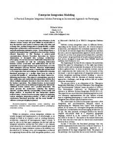
2.ERP5 The ERP5 project [4][5] is a FOS-ERP that aims at offering an integrated management solution based on the open source Zope platform, written in the Python scripting language. This platform delivers an object database (ZODB), a workflow engine (DCWorkflow), and rapid GUI scripting based on XML. Additionally, ERP5 incorporates data synchronization among different object databases, through the implementation of the SyncML XML based protocol, and a object-relational mapping scheme that stores indexing attributes of each object in a relational database, allowing much faster object search and retrieval, in comparison to ZODB, and also analytical processing and reporting. This project was initiated in 2001 by two French companies, Nexedi – its main developer, and Coramy – its first user, and since then is in development and use by a growing community from France, Brazil, Germany, Luxembourg, Poland, Senegal, and India, among others. ERP5 is named after the five core business entities that define its Unified Business Model (UBM, Figure 1): Resource: describes an abstract resource in a given business process (such as individual skills, products, machines etc). Material lists, as well as prototypes are defined by the relationship between nodes. Node: a business entity that receives and sends resources. They can be related to physical entities (such as industrial facilities) or abstract ones (such as a bank account). Metanodes are nodes containing other nodes, such as companies. Path: describes how a node accesses needful resources. Movement: describes a movement of resources among nodes, in a given moment and for a given period of time. For example, such movement can be the shipping of raw material from the warehouse to the factory. Item: a physical instance of a resource.
the UBM. This mapping is documented by a proper instance’s lexicon. For example, debit and credit values can be mapped to the Quantity property of the Item class. Its behavior is implemented through workflows, which implement the business processes, and consider the concept of Causalities (chains of related events). Very flexible and extensible modules, called Business Templates, are also provided for Accounting, Production Planning, Payroll, Finance, MRP, CRM, Trading, Electronic Commerce, Reporting, and others.
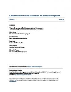
3.GERAM and ERP5 GERAM provides a description of all elements recommended in enterprise engineering and a collection of tools and methods to perform enterprise design with success [6]. It also considers enterprise models as an essential approach to support enterprise engineering and integration [7][8].GERAM defines enterprise engineering methodologies (EEM) and their enterprise modeling languages (EML), used to describe aspects of the enterprise, like the structure, content, and behavior of the entities to be modeled. Based on these elements, the proposed process defines a development architecture for the ERP5 system. Following these terms, the development process here presented is itself an EEM and the EML considered is the Unified Modeling Language (UML), because it is a de facto standard for modeling object oriented information systems, and it is extensible. According to GERAM, the modeling language semantics may be defined by ontologies, metamodels and glossaries that are collectively called Generic Enterprise Modeling Concepts (GEMC). For the ERP5 project, its Unified Business Model, and other concepts like Lexicons and Causalities compose the GEMC. The modeling process results in enterprise models (EM) that represent all or part of the enterprise operations, its organization and management, and its control and information systems. These models can be transformed into an enterprise operational system (EOS), or be used to realize simulations, and to promote changes in the enterprise. To facilitate the modeling process, partial models (PEM), which are reusable models of human roles, processes and technologies, are used. In ERP5, the development process will generate EM, and the EOS is the ERP5 particular implementation itself. An EOS is a set of enterprise modules (EMO) that support the operational use of enterprise models. EMO provide prefabricated products like human skills, common business procedures or IT infrastructure services, used as components in the implementation of the EOS. Enterprise engineering tools (EET) support the methodologies and languages used for enterprise modeling. For the proposed process, CASE tools and ERP5 development support tools – described later in this article - act as EET. Table 1 summarizes the mappings between GERAM and the development process elements. GERAM also defines seven life-cycle phases (Figure 2) for any enterprise or any of its entities that are pertinent during the life of the entity. These phases, which can be subdivided further into several lower level activities, can be summarized as follows:
Figure 1. ERP5 Unified Business Model. The structure of ERP5 instances is defined through mappings of the particular instance concepts to the five core concepts and supportive classes or, in very rare cases, through the extension of
1. Identification: identifies the particular enterprise entity in terms of its domain and environment. 2. Concept: conceptualizes an entity’s mission, vision, values, strategies, and objectives.
3. Requirements: comprise a set of human, process, and technology oriented aspects and activities needed to describe the operational requirements of the enterprise. 4. Design: models the enterprise entity and helps to understand the system functionalities. 5. Implementation: the design is transformed into real components. After tested and approved the system is released into operation. 6. Operation: is the actual use of the system, and includes user feedback that can drive to a new entity life cycle. 7. Decommission: represents the disposal of parts of the whole entity, after its successful use. The development process here presented focuses on Requirements, Design, and Implementation phases. Since it is also based on an interactive and incremental life cycle, it is considered that there are no clear borderlines between the phases; furthermore, in some situations, other phases, like Concept and Operation can be touched, as will be shown afterwards.
Identification Concept
Life Cycle Phases
Requirements
Table 1. GERAM concepts and respective development process elements. GERAM Element
Development Process Element (s)
EEM EML GEMC
Development Process Activities UML Universal Business Model, Lexicons, Causalities Business Processes Models ERP5 Instance Business Templates, Reference Models Instance Modules CASE tools, ERP5 development and project management tools
EM EOS PEM EMO EET
4.ENTERPRISE MODELING
Preliminary Design Detailed Design
top of a composition of UP, GERAM, and new concepts. A current investigation theme is the relation between the proposed process with Domain Specific Modeling Languages (DSML). DSML represent system elements and their relationships as well as their transformations to platform-specific artifacts [10], exactly what this process proposes: transform from enterprise models to source code.
Design
Implementation Operation Decommission
Figure 2. GERAM Life Cycle Phases. One of the GERAM components is the methodology to engineer the entity considered. For this proposal, it is used a variation of the Unified Process (UP) [9] to describe an ERP5 instance development project lifecycle. The adopted UP’s concepts are: (i) the four phases – Inception, Elaboration, Construction, and Transition, and (ii) the basic axioms – use case and risk driven, architecture centric, and interactive and incremental. However, the use of the Unified Business Model and specific modeling workflows, makes the process here presented differ from UP, by adding, extending, or substituting some activities. Also, it is important to note that the phases from Requirements to Implementation of GERAM Life Cycle, must be interpreted not as a waterfall one, but as an interactive and incremental cycle, thus, looping among the referred phases until the system is complete. To accomplish this, workflows are defined for the life cycle phases defined in GERAM that are directly related to software development: Enterprise workflow for the Conception phase, Requirements Workflow in Requirements phase, Analysis and Design Workflows in Design phase, Implementation Workflow in Implementation phase, and Deployment activities as the initial part of the Operation phase. As a result, a new kind of development process can be defined for the ERP5 project, built on
For the case of enterprise information systems, it is vital to include in the development methodology, enterprise modeling concepts and methods to better capture organizational aspects and requirements, such as its processes, manufacturing resources and structure [8][11]. Therefore, a specific Enterprise Modeling workflow, which concentrates on the modeling of function, information, resources, and organization views, according to the GERAM modeling framework, is employed. This workflow stands between UP’s Concept and Requirements phases.
Figure 3. Enterprise Modeling Workflow. The Enterprise Modeling workflow consists of the activities shown in Figure 3, and can be summarized as follows: 1. Objectives Modeling: define the strategic planning of the organization. 2. Process and Activities Modeling: define the behavioral and functional aspects of the organization. These activities are directly related to the Business Modeling discipline.
3. Resources Modeling: describes the human, informational and technological resources. 4. Information Modeling: describe, in high level of abstraction, the information handled by the organization.
5. Organization Modeling: describe the structure, in departments for instance, of the organization. A detailed description of these modeling activities can be built based on CIMOSA [7], or Eriksson & Penker approaches [12], depending on the kind of enterprise being modeled and the preferences of modelers. The general goal of this phase is to discover the main resource flows and the structural organization of the enterprise being modeled.
5.REQUIREMENTS The information captured by the Enterprise Modeling workflow is detailed and consolidated as requirements to the information system, following the Requirements Workflow, shown on Figure 4, which is supposed to identify the requirements for the ERP5 instance. Its activities are the following: 1. System Requirements Definition: should provide a document with basic requirements for the instance. These requirements are a composition of features identified by the Process and Activities Modeling phases of the Enterprise Modeling workflow with some more detailed system’s functionalities that can be identified at this point and are necessary to the consolidation of the business process information needs. 2. Use Case Identification: Use Cases are identified from the activities of an Activity Diagram that represents a specific business process. This identification complements the requirements definition through the definition of the basic system’s architecture. 3. Basic Iteration Planning: although the detailed aspects of the system will be known only afterwards, it is necessary to define a basic iteration execution plan. This plan establish priorities to use cases according to their criticality, defined by the aggregation of the following criteria: being central to the system architecture, or representing primary business process, high risk functions, high complexity, high aggregated value for the client, and non-dominated or developed technology.
a chain that associates a requirement to one or more use cases (if it is a functional requirement), and then the use cases to project activities. With these tools it is possible to keep track of all requirements implementation and associated resources and costs, in every development phase. In that way, customer inquiries on implementation course are easily answered and change management is facilitated for both the product and the process. Of course, due to the iterative nature of the process, data about the iterations is constantly updated.
6.ANALISYS After the enterprise modeling stage it is necessary to define a method to transform models into source code. In other words, define a set of activities that will take care of the issues related to transform structural and behavioral models into source code that reflects business requirements. This method is conceptually related to the Preliminary Design phase in GERAM. The workflow for this phase is presented in Figure 5. This workflow is characterized by the parallel execution of its interactive activities, which were specifically created for the ERP5:
5 Abstractions Test
Use Case Detail: Actions Document Analisys
Lexicon Building
[ No Core Extension ]
[ Core Extension ]
Core Extension
Figure 5. Analysis Workflow.
Figure 4. Requirements Workflow. ERP5 provides a tool, called ERP5 Feature, which aims to help the register and change management of system requirements. This tool is integrated with ERP5 Use Case and ERP5 Project, creating
Use Case Detail – Actions: it is used two-column Use Cases, one for describing actors’ actions and other for describing system’s responsibilities or reactions [13]. For this incremental process, in the Analysis activities only the actions and some basic reactions are described, since detailed reactions are identified only during the Design activities. Security issues can also be addressed in this activity. A Use Case related to a functional requirement has at least one document associated to it. Documents Analysis: ERP5 is a document oriented ERP based on document workflows, because documents are considered a common language understood by all employees in any
organization. Therefore, this activity consists of identifying the documents that support a given Use Case, starting by ERP5 default documents that provide a basis for customization. 5 Abstractions Test: this is one of the most important activities in ERP5 modeling. The goal of this test is to find out if the UBM can support the Use Case, or in other words, if the resources flows described in a given business process can be represented by the core model. If not, Core Extensions are implemented. Lexicon Building: maps concepts from the business world of the client to ERP5. This is necessary because ERP5 names are quite general – to support reuse. In some cases it is interesting to include an optional activity of designing an Object or a Collaboration Diagram. These diagrams can help the understanding of the Use Case, in special when extensions to the core are needed. Also, a first draft of a State Diagram, representing the basic Use Case process, can be done. This phase is supported by ERP5 Use Case Module, which allows the definition of Use Cases, including their actors and scenarios; ERP5 Document Analysis Module, which main purpose is to identify and name documents and their items; and ERP5 Lexicon Module, which maps domain terms into ERP5 terms. The Use Case Module is integrated to ERP5 Features Module, so that consistency among Requirements and UCs can be checked automatically.
2. Design Statechart Diagram: states names correspond to the state of the system in a particular moment. From the UC, verbs in the actions column identify state transitions; in the reaction column verbs identify states internal activities. Figure 7 shows an example of a single UC row with a correspondingly transition in a statechart diagram. 3. Fill WARC Table: WOOM uses a modeling artifact, named WARC Table (Workflow – Action/Reaction – Responsible – Collaborators), which is used to associate structure to behavior, guaranteeing encapsulation in object-oriented design. For the process here proposed, a different use of the WARC table is considered: a state transition is associated for each action, and a state internal action to each reaction – forming the Responsible column of the table. The objects that are manipulated by the transition or internal action are listed in the Collaborators column (the objects that participates on the UC were already identified in the Analysis phase). Table 2 shows the rows that represent in the WARC Table the UC step exemplified on Figure 7. 4. Write Contracts: This final step takes care of writing a contract [15] for each action and reaction. Contracts will determine what each transition/internal activity must do to collaborate to the workflow correct realization. For describing operation’s responsibilities pseudo-code, proto-code, plain text, Object Constraint Language (OCL) and Activity Diagrams can be used. Even more complex contract approaches may be used, like extending the Python interpreter to directly support the Design By Contracts method [16].
7.DESIGN
Figure 7. Example transformation from a Use Case row to a statechart diagram’s transition and state in WOOM. Figure 6. Design Workflow. The Design workflow is based on an adapted version of the Workflow, Object Oriented Method (WOOM) [14]. This method takes into consideration that the underlying platform supplies an object-oriented language and a state based workflow engine, and although it was created for generic purposes, it fits in ERP5 environment, with some modifications. The activities of this phase are represented by Figure 6, and described as follows: 1. Use Case Detail – Reactions: the reactions correspond to the second column of the UC, they define what the system is suppose to do according to an actor’s action.
At this point it is interesting to discuss briefly about the use of state machines to model and implement workflows, since, for UML users, there is a growing tendency of describing workflows based on Activity Diagrams [17][18]. This kind of diagrams evolved from statechart specializations to a Petri Nets like form, tendency identified by some researchers even before the launching of UML 2.0 specifications [19]. However, the proposed process must use state machines to define workflows because the underlying development platform does so. Also, it is, most of times, straightforward to make translations between Statechart Diagrams and Petri Nets [20]. Moreover, it is reasonable to use Activity Diagrams to model business process in the Enterprise Modeling phase, and then Statechart Diagrams to model workflows - in the Design phase. From this viewpoint, it is
legitimate to consider that the correct use of states and states activities can represent most workflow patterns. Besides that, there are plenty of tools and methods for mathematically validating state based workflows [21][22] [23], reducing time and consequently costs.
8.IMPLEMENTATION Implementation is the final step of every development process, and therefore it is the one that is more influenced by platform particularities. Zope, the underlying ERP5 platform, uses the concept of Portal Types to implement new types into its Content Management Framework. Therefore, any development process related to ERP5 must take into account this concept. In this process, it is understood that the workflow activities defined in the Design phase implements the behavior of the process, and a portal type implements its structure. Portal types are an assembly of ERP5 core classes’ implementations, related GUI and a workflow. If the business process holds internal variables, the workflow object can hold this values as object attributes. The Implementation workflow is described in Figure 8, and can be described as follows:
5. Integration Testing: the Use Case is tested in conjunction with others to check consistency among functionalities that must work integrated. ERP5 Generator is a tool that generates structural, behavioral, and GUI elements from specific artifacts: WARC Tables: are used to check the consistency between Class and Statechart Diagrams. Class Diagrams: are used to generate the structure (portal types). From these diagrams, Python classes, their relational mapping and basic GUI for object maintenance (create, destroy, getters and setters) are generated. Statechart Diagrams: are used to generate behavior (workflows). ERP5 Generator parses XMI files exported by a compatible CASE tool, check it against a WARC Table, and creates the portal type and associated workflow. A plug-in for the Use Case Module implements WARC tables with some basic features like: (i) prefilled with all corresponding transitions and state activities (actions and reactions), (ii) lists of available classes for responsible and collaborators columns, and (iii) automatic updating of class diagrams. These features will avoid ordinary modeling mistakes and accelerate code transformation. Table 2. Example WARC Table row. Action/Reaction
Responsible
Collaborators
Select item
includeItem()
Product
Insert item on list
InsertNewItem()
Purchase, Item
For both Class and Statechart Diagrams, Generator takes care of UML constructions that are not used by Python Classes and DCWorkflow, logging warnings that indicate incompatibilities generated by non-supported UML features. As for now, Generator already generates code for both structure and behavior, GUI generation, and WARC integration, but Model Checking is still a work in progress. A tool named ERP5 Subversion allows the integration of version control with the other development tools.
9.CONCLUSIONS
Figure 8. Implementation Workflow. 1. Structure and Behavior Generation: using a code generation tool – ERP5 Generator, the portal type and related workflow are automatically generated from a XMI file. 2. Prepare Test Documents: these documents are instances of each scenario of each Use Case with specific values. These documents can be written in any language that can be understood by programmers and Quality Assurance personnel. 3. Code Completion: represents the implementation in source code of the algorithms of the workflow’s transactions and internal activities. 4. Unit Testing: is run by a testing script, which automates the steps described in the Test Documents. This activity is supported by the ERP5 testing framework.
The core goal of the presented process is to supply ERP5 adopters with the option of a model-driven development method based on proper practices and tools. Practice has shown that this process, if correctly used, can embed all knowledge necessary to make the system development the more systematic and automated possible. It represents a leaner model-driven approach, due to its simplified workflows, and the high level of reuse offered by ERP5 framework, which reduces not only the programming effort, but also the number and complexity of modeling tasks. Moreover, the intensive use of highly integrated tools enhances productivity, easies project management and accountability, and reduces modeling and coding errors Aiming to enhance even more the use of tools during the development, ERP5 Déployer, a tool fully adherent to the proposed development process and integrated with all others cited on this work, is in development. This tool will automate the development workflows, provide template documents for managers – based on the Project Management Body of Knowledge (PMBoK), and improve consistency checks among the successive model transformations that occur during the
process. Furthermore, it is in development a Reference Models library that will complete the shift from a code-based ERP5 customization paradigm to the model-based customization used by the process here described.
[11] H. Shen, B. Wall, M. Zaremba, Y. Chen, J. Browne, “Integration of Business Modeling Methods for Enterprise Information System Analysis and User Requirements Gathering”, Computers in Industry, vol. .54, n. 3, pp. 307-323, 2004.
10.REFERENCES
[12] H. E. Eriksson, M. Penker, Business Modeling with UML. New York: John Wiley & Sons, 2000.
[1] R. A. de Carvalho, “Issues on Evaluating Free/Open Source ERP Systems,” in Research and Practical Issues of Enterprise Information Systems (IFIP Series), New York: SpringerVerlag, pp. 667-676, 2006.
[13] Wirfs-Brock, R. 1993.Designing Scenarios: Making the Case for a Use Case Framework. Smalltalk Report Nov-Dec 1993. NY, NY: SIGS Publications.
[2] M. Odeh, R. Kamm, “Bridging the Gap Between Business Models and System Models,” Information and Software Technology, vol. 45, pp. 1053-1060, 2003.
[14] R. A. De Carvalho, “Device and Method for Information Systems Modeling”, Brazilian Patent PI0501998-2, June 09, 2005.
[3] R. de Campos, R. A. de Carvalho, J. S. Rodrigues, “Enterprise Modeling for Development Processes of Open Source ERP”, in Proc. 18th Production and Operation Management Society Conference, Dallas, USA, 2007.
[15] B. Meyer, “Applying Design by Contracts”, IEEE Computer, vol. 25, n. 10, 1992.
[4] J-P. Smets-Solanes, R. A. De Carvalho, “ERP5: A NextGeneration, Open-Source ERP Architecture,” IEEE IT Professional, vol. 5, pp. 38-44, Jul. 2003. [5] J-P. Smets-Solanes, R. A. De Carvalho, “An Abstract Model for An Open Source ERP System: The ERP5 Proposal”, in Proc. 8th International Conference on Industrial Engineering and Operations Management, Curitiba, Brazil, 2002. [6] IFIP – IFAC GERAM: Generalized Enterprise Reference Architecture and Methodology, IFIP – IFAC Task Force on Architectures for Enterprise Integration, 1999. [7] K. Kosanke, F. Vernadat, M. Zelm, "CIMOSA: Enterprise Engineering and Integration, Computers in Industry, vol.40, n. 2, pp. 83-97, 1999. [8] F. B. Vernadat,” Enterprise Modeling and Integration (EMI): Current Status and Research Perspectives,” Annual Reviews in Control, vol. 26, pp. 15-25, 2002. [9] J. Arlow, I. Neustadt, UML and the Unified Process – Practical Object-Oriented Analysis & Design. London: Addison Wesley, 2002. [10] K. Balasubramanian, A. Gokhale, G. Karsai, J. Sztipanovits, S. Neema, “Developing Applications Using Model-Driven Design Environments”, IEEE Computer, vol. 39, Feb. 2006, pp. 33-40.
[16] R. Plösch, “Design by Contract for Python”, in Proc. of IEEE Joint Asia Pacific Software Engineering Conference, Hong Kong, 1997. [17] OMG UML 2.0 Superstructure Specification, OMG Standard, 2005. [18] R. B. France, S. Ghosh, T. Ding-Trong, A. Solberg, “Model Driven Development and UML 2.0: Promises and Pitfalls”, IEEE Computer, vol. 39, Feb. 2006, pp. 59-66. [19] J. Delatour, F. De Lamotte, “ArgoPN: A CASE Tool Merging UML and Petri Nets,” in Proc. 1st International Workshop on Validation and Verification of Software for Enterprise Information Systems, Angers, France, 2003, pp. 94-102. [20] W. van der Aalst, K. van Hee, Workflow Management, Cambridge: MIT Press, 2004. [21] A. Knapp, S. Merz, “Model Checking and Code Generation for UML State Machines and Collaborations”, in Proc. 5th Workshop on Tools for System Design and Verification, Augsburg, 2002. [22] D. Latella, I. Majzik, and M. Massink, “Automatic Verification of a Behavioral Subset of UML Statechart Diagrams Using the SPIN Model-Checker,” Formal Aspects in Computing, vol. 11, n. 6, pp. 637–664, 1999. [23] J. Lilius and I. P. Paltor, “Formalizing UML State Machines for Model Checking,” in Proc. 2nd Int. Conf. in UML, Berlin, 1999.