FIR filter design algorithm is the Parks-McClellan algorithm [7]. This algorithm is based on linear programming, and it is com- putationally efficient. However ...
Equiripple FIR Filter Desig e FFT Algorithm A. ENIS GETIN, OMER N. GEREK, AND YASEMIN YARDIMCI The problem of designing an FIR filter consists of deterhe Fast Fourier Transform (FFT) algorithm has been used in a variety of applications in signal and image mining the impulse response sequence, h[n],or its system processing [1-51. In this article, a simple procedure function, H(z), so that given requirements on the filter refor designing Finite-extent Impulse Response (FIR)discrete- sponse are satisfied. The filter requirements are usually specitime filters using the FFT algorithm is described. The zero- fied in the frequency domain, and only this case is considered phase (or linear phase) FIR filter design problem is here. The frequency response, H(e'@),corresponding to the formulated here to altemately satisfy the frequency domain impulse response A[.], with a support, I , is expressed as constraints on the magnitude response bounds and time domain constraints on the impulse response support 16-81, The design scheme is iterative in which each iteration requires ne1 two FFT computations. The resultant filter is an equiripple approximation to the desired frequency response. Notice that H(e'O) is a periodic function with period 2n.This The main advantage of the FFT-based design method is implies that by defining H(e'O) in the region { -n< o 2 n} the its implementational simplicity and versatility. Furthermore, frequency response of the filter for all 0) E R is determined. the way the algorithm works is intuitive and any additional Filter specifications are usually given in terms of the constraint can be incorporated in the iterations, as long as the magnitude response, IH($@)I. In most applications a two-level convexity property of the overall operations is preserved [6]. magnitude design, where the desired magnitude levels are In one-dimensional cases, the most widely used equiripple either 1.0 (in passbands) or 0.0 (in stopbands), is of interest. FIR filter design algorithmis the Parks-McClellanalgorithm [7]. Consider the design of a lowpass filter whose specificaThis algorithm is based on linear programming, and it is com- tions are shown in Fig. 1.The magnitude of the lowpass filter putationally efficient. However, it caninot be generalized to ideally takes the value 1.0 in the passband region, Fp = [-CO,, higher dimensions. Extension of om design method to higher a,],and 0.0 in the stopband region, F, = [-E, -op] U lo,, n]. dimensions is straightforward. In this case two Multi-DimenAs magnitude discontinuity is not possible with a finite filter sional (M-D) FFT computations are needed in each iteration [8]. support it is necessary to interpose a transition region, F,, between F, and F,. Also, magnitude bounds 1 - S,< IH(o)l< Zero Phase FIR Filter Specifications 1 + 6, in the passband, F,, and IH(o)l_< 6, in the stopband, F, and Design Considerations , are specified, where the parameters 6, and 6, are positive real numbers, typically much less than 1.O. Consequently,the In this section, the zero-phase FIR filter design problem is lowpass filter is specified in the frequency domain by the described and the notation of the article is introduced. The term FIR filter refers to a linear shift-invariant system regions, Fp,F,, and the tolerance parameters, 6, and 6,. Other whose input-output relation is represented by a convolution widely used filters, bandpass, and highpass filters are specified in a similar manner. The FFT based procedure can easily accommodate arbitrary magnitude specifications y[.] = C h [ k ] x [ n k], as well. k d In order to meet given specifications, an adequate filter where x[n] and y[n]are the input and the output sequences, order (the number of nonzero impulse response samples) respectively, h[n]is the impulse response of the filter, and I needs to be determined.if the specifications are stringent with is the filter support. The FIR filters have only a finite number tight tolerance parameters and small transition regions then of nonzero coefficients so that the support I is a bounded the filter support region, I , must be large. In other words, there region. Usually the filter support, 1,is selected as a symmetric is a trade-off between the filter support region, I , and the region centered at the origin, i.e., Z = { -N, -N+l, ..., -1, 0, 1, frequency domain specifications. In the general case the filter ..., N } . The causal FIR filter can be obtained by simply order is not known a priori and may be determined through an iterative process. If the filter order is fixed then the delaying h[n]by N samples.
T
60
IEEE SIGNAL PROCESSING MAGAZINE 1053-5888/97/$10 0001997 IEEE
MARCH 1997
where H i d ( i Wis) the ideal filter response, Ed(o)is a positive function of W, which may take different values in different passbands and stopbands, and F, is the union of passband(s) and stopband(s) of the filter (note that H ( P ) is real for a zero-phase filter). Usually, Ed(w) is chosen constant in a passband or a stopband. For instance,
Hid(W)
=
1, if w E Fp 0, if W E &
(7)
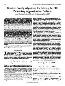
and 1. Frequency response specifications for the lowpass filter ( I - 6, 5 I H(w) I 5 I + 6, for U) E Fp and I H(w)l< &for w E Fs).
tolerance parameters, 6, and 6,, must be properly adjusted to meet the design specifications. Phase linearity or “zero phase” condition is important in many filtering applications [3, 181, and the discussion here is limited to the case of “zero phase” design, with a purely real frequency response. The term “zero phase” is somewhat misleading in the sense that the frequency response may be negative at some frequencies. In frequency domain the zero-phase or real frequency response condition corresponds to
H ( P ) = H*($“),
(3)
where H*(dW) denotes the complex conjugate of H(dW). The condition (3) is equivalent to h[n]= hY[-n]
I = { n = -N, -N+1,..., -1,O,1, ...,N} .
The iterative method begins with an arbitrary finite-extent, real sequence h,[nl that is symmetric (h,[n]= h, [-n])around the origin. A good candidate for the initial estimate can be obtained from the inverse Fourier Transform of the ideal frequency response hid[nl= F’[H,(W)I as
hid[n]if n E I 0, otherwise Each iteration of the algorithm consists of making succes-
( 5 ) sive imposition of spatial and frequency domain constraints
implying a symmetric filter about the origin.
Iterative Design Method We now consider the FFT based design procedure, which leads to an equiripple frequency response. In this method we formulate the zero-phase FIR filter design problem in such a way that time and frelquency domain constraints on the impulse response are alternately satisfied through an iterative algorithm [6, 91. The iterative algorithm requires two FFT computations in each iteration. The frequency response, H(dW),of the zero-phase FIR filter is required to be within prescribed upper and lower bounds in its passbands and stopbands.Let us specify bounds on the frequency response H(d7 of the FIR filter, h[n],as folYows:
onto the current iterate. The k-th iteration consists of the following steps: Compute the Fourier Transform of the k-th iterate h J n ] on a suitable grid of frequencies by using an FFT algorithm, Impose the frequency domain constraint as follows
I
(
Hid(eiw ) + Ed (W) if Hk ejm)> Hid(e@) + Ed (W)
Gk(ejm)= Hid(ejm)- &(a) if Hk(ejw) < Hid(ejm)- Ed(w)
Hk
(ejo)
otherwise.
(11)
compute the inverse Fourier Transform of Gk(ejw) zero out gk[n]outside the region Z to obtain hk+l as g k [ n ] ,if n c I
h,+,[nl= 0,
MARCH 1997
(9)
(4)
in time-domain.Makiing a common practical assumption that h[n]is real, the above condition reduces to
h[n]= h[-n],
for the lowpass filter example of the previous section. Inequality (6) is the frequency domain constraint of the iterative filter design method. In time domain the filter must have a finite-extent support, I, which is a symmetric region around the origin in order to have a zero-phase response (or to achieve phase linearity). The time domain constraint requires that the filter coefficients must be equal to zero outside the region,
IEEE SIGNAL PROCESSINGMAGAZINE
otherwise
61
. Initial Filter hob)
Impose Time
Inverse Fourier Transform via FFT
Impose Bounds in Fourier
1
h (n) =
gkb)
if n E I
0
ifnel
1, o ~ { O < 0 ) 5 0 . 4 ~ } 0, o ~(0.671.ICO 5 K }
k+l
. Flow diagram of the itevativefilter design algorithm.
if the Mean Squared Error between the iterates hk[n]and hk+l[n]is less than a predefined threshold, then exit. The flow diagram of this method is shown in Fig. 2. It can be proven that the iterative FIR filter design algorithm is globally convergent. The proof is based on the method of Projections onto Convex Sets (POCS) [10-131. The constraints (6) and (9) define two convex sets in the set of square o
{.;
'i
summable sequences, -e2 = h : z l h [ n ] /