Apr 11, 2011 ... Fourier Transforms - Approach to Scientific Principles ... The workflow of typical
GPS software ..... Understanding GPS Principles and ... In order to correctly
reference this scholarly work, feel free to copy and paste the following:.
9 Optimized FFT Algorithm and its Application to Fast GPS Signal Acquisition Lin Zhao, Shuaihe Gao, Jicheng Ding and Lishu Guo College of Automation, Harbin Engineering University China 1. Introduction The essence of GPS signal acquisition is a two-dimensional search process for the carrier Doppler and code phase, generally including correlator, signal capture device, and logic control module. The disposal efficiency of correlator would affect the capture speed of the whole acquisition process. Because of the corresponding relation between frequencydomain multiplication and time-domain convolution, the Discrete Fourier Transform (DFT) could be applied to play the role of the correlator, which is suitable to implement for computers (Akopian, 2005) (Van Nee & Coenen, 1991). However, with the performance requirements of GPS receivers increasing, especially in the cold start and the long code acquisition, such as P code, the acquisition time should be furtherly reduced. Therefore, the fast discrete Fourier transform processing approach, that is, Fast Fourier Transform (FFT), is described, including radix-2, radix-4, split-radix algorithm, Winograd Fourier Transform Algorithm (WFTA) which is suitable for a small number of treatment points, and Prime Factor Algorithm (PFA) in which the treatment points should be the product of some prime factors. According to the actual needs of GPS signal acquisition, an optimized FFT algorithm was put forward, which comprehensively utilize the advantages of different FFT algorithms. Applying optimized FFT algorithm to GPS signal acquisition, the results of simulations indicate that the improved processing could reduce the acquisition time significantly and improve the performance of GPS baseband processing.
2. Analysis on GPS signal acquisition 2.1 Basic characteristics of GPS L1 signal There are three basic components in GPS signal: carrier waves, pseudo-random numbers (PRN) codes and navigation message (D code). Among them, the carrier waves are located at the L-band, including L1-band (1575.42MHz) which is with the most common application, L2-band (1227.6MHz) and L5-band (1176.45MHz). There are two basic types of PRN codes, the coarse/ acquisition (C/ A) code and the precise (P) code. The simplified structure of GPS L1 signal is shown in Fig. 1. The frequency of carrier wave is 1575.42MHz. The code rate of C/ A code and P code are 1.023MHz and 10.23MHz respectively. The data rate of D code is 50Hz.
www.intechopen.com
158
Fourier Transforms - Approach to Scientific Principles
÷10 Oscillator frequency 10.23MHz
×154
L1 1575 .42MHz
C/A code 1.023MHz
P code 10.23MHz
D code 50Hz
×1
Fig. 1. The simplified structure of GPS L1 signal C/ A code is used to achieve spread spectrum of D code. Compound code C/ A D could be gained when the D code is spreading, and the code frequency is extended to 1.023MHz. Compound code P D could be gained when the P code is spreading, and the code frequency is extended to 10.23MHz. And then multiply the spread spectrum signal with the L1 carrier wave to complete the modulation. Quaternary phase shift keying (QPSK) is applied in the modulation of L1 signal, where the in-phase carrier component is modulated with compound code C/ A D, and the orthogonal carrier components is modulated with compound code P D, so the L1 signal transmitted by satellites could be expressed as: (1) Where and are powers of different signal components respectively, , and are D code, C/ A code and P code of satellite respectively, is the frequency of carrier wave, and is the initial phase. The process of spread spectrum and modulation for GPS transmitted L1 signal could be shown in Fig. 2 (Kaplan, & Hegarty, 2006).
L1 carrierwave (1575 .42MHz) Navigation message (50Hz) PRN code (1.023MHz)
Broadcast signal
Fig. 2. The spread spectrum and modulation for GPS L1 signal In fact, P code mainly used for the military, and is not open to civilian use, so the received L1 signal could be simplified to include carrier wave, C/ A code and D code in the research of GPS C/ A code acquisition.
www.intechopen.com
Optimized FFT Algorithm and its Application to Fast GPS Signal Acquisition
159
2.2 Signal acquisition in GPS receiver The original GPS signal, which is interfered and attenuated in the transmission path, is gained by the receiver antenna. Radio Frequency (RF) front-end completes the frequency conversion and analog-digital conversion for the weak signal, where the high frequency analogy signal is transformed into Intermediate Frequency (IF) digital signal which is beneficial to computer processing. The coarse and precision estimates of carrier Doppler frequency shift and PRN code phase are achieved by acquisition and tracking in the baseband processing, and then dispreading and then demodulation of navigation message should be completed. Actually it is the opposite process of spreading and modulation mentioned above. Position calculation could be realized by adequate information gained by baseband module (Michael, & Dierendonck, 1999). The workflow of typical GPS software receiver is shown in Fig. 3.
Fig. 3. The workflow of GPS receiver As a part of baseband signal processing in GPS receiver, the main aim of signal acquisition is to find visible satellites, and estimate their C/ A code phase and carrier Doppler frequency shift respectively. The essence of GPS signal capture is a two-dimensional search process for the carrier Doppler and code phase. The PRN code phase and carrier Doppler frequency could be considered respectively. As shown in Fig. 4, each C/ A code contains 1023 code elements, and search step with one code element would be commonly selected. In high dynamic environment, the Doppler frequency ranges from -10kHz to +10kHz, and 1kHz search step is generally selected. In the above search process, once the code phase and the carrier Doppler frequency shift generated by local oscillator are close to the receiving code phase and Doppler frequency shift, there will be a correlation peak for the randomness of C/ A code. Generally, the code phase error is less than half a symbol, and the Doppler frequency shift error is within [500Hz, 500Hz]. At this time, the code phase and carrier Doppler frequency parameters which the peak point corresponds could be the acquisition results, and then the baseband processing enters the second stage, signal tracking. When the predetermined frequency points are tested one by one in time-domain, the large computation would cause great time-consuming, unless there are a lot of hardware resources as the supplement. Fortunately, we can use another method to get all results the 1023 possible code phases corresponding for each frequency point, which is the acquisition method based on FFT.
www.intechopen.com
160
Fourier Transforms - Approach to Scientific Principles
3. GPS signal acquisition method based on FFT Processing speed is constrained in the traditional acquisition method based on time domain, so the acquisition method based on Fourier transform is always used in current software receiver (Li, Zhang, Li, & Zhang, 2008).
Doppler frequency shift
Code phase
Fig. 4. Two-dimensional search for Doppler frequency shift and C/ A code phase 3.1 Corresponding relation between frequency-domain and time-domain Using circular correlation theory, convert the correlation of received signal and local generated signal in the time-domain to spectrum multiplying in the frequency-domain (Akopian, 2005) (Van Nee & Coenen, 1991). Assumed is the circulating moving local code, is the number of corresponding sampling points, the output of correlator would be expressed as: (2) Do discrete Fourier transform (DFT) of
, (3)
And then,
could be transformed to
(4) If
and
are DFT forms of
and
, (5)
www.intechopen.com
161
Optimized FFT Algorithm and its Application to Fast GPS Signal Acquisition
is real signal, the complex conjugates of As the local code expressed by and respectively. The amplitude output is
and
could be
(6) According to the correlation of original signal and local code, adjudicate the relevant results. The number of visible satellites, and the estimation of code phase and Doppler frequency shift could be drawn. So the process of signal acquisition based on FFT could be expressed as follows: (7) is the inverse fast Fourier transform (IFFT) operation, Where operation, and is the conjugate form of .
is the FFT
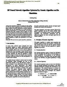
3.2 GPS signal acquisition based on FFT The signal received by antenna would go though amplification, mixing, filtering, and analogdigital conversion in RF front-end, and its output is the IF digital signal. The local carrier wave numerical controlled oscillator (NCO) would generate two-way mutually orthogonal signal and , which would be utilized to multiply the IF digital signal respectively. As shown in Fig. 5, the value of branch I and branch Q are regarded as real part and imaginary part respectively. Construct a new complex sequence with the form of (8) Do FFT of this new sequence, and do FFT of the local generated C/ A codes at the same time. Then complex multiplications are carried out between these two FFT values. After correlation, IFFT operations are carried out for it. Calculate the modulus of IFFT results one by one, and find the maximum value, which is shown in Fig. 6. Comparing the maximum value and the pre-set threshold, if the maximum value is less than the threshold, it means there is no effective signal. But if the maximum value is higher than the threshold, it means the acquisition is successful, and the received signal code phase and Doppler frequency shift would appear in the location of peak. cos(ωt)
IF signals
I
FFT Q
sin(ωt)
C/A code
Local oscillator
Logic judgement
Fig. 5. Signal acquisition process based on FFT
www.intechopen.com
Complex conjugate
|Σ|2
IFFT
162
Fourier Transforms - Approach to Scientific Principles
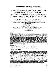
The corresponding C/ A code and Doppler phase shift could be obtained in the same time, so it is obviously that the FFT operations play a crucial role in the acquisition, especially in the quick acquisition for high dynamic environments. The efficiency of FFT computation would determine the capture speed and whole performance of the receiver.
Fig. 6. The peak of signal acquisition (PRN=13)
4. Description on FFT algorithms DFT of
could be defined as: (9)
According to the definition of equation (9), its computation of complex multiplication is , and its computation of complex addition is , whose operation is quite large. To calculate DFT rapidly, FFT algorithms came into being in nearly half a century with the purpose to reduce the calculation of DFT (Duhamel, & Vetterli, 1990). Since Cooley and Tukey proposed FFT algorithm, the new algorithms have emerged constantly. In general, there are two basic directions. One is that the length of sequence , such as radix-2 algorithm, radix-4 equals to an integral power of 2, with the form of algorithm and split-radix algorithm. The other is that the number of points does not equal to an integer power of 2, with the form of , which is represented by a class of Winograd algorithm, such as prime factor algorithm and WFTA algorithm (Burrus, & Eschenbacher, 1981). But the basic idea of various FFT algorithms is to divide the long sequence to short sequences successively, and then make full use of the periodicity, symmetry and into DFT with a reducibility of rotation factors to decompose DFT with a large number combination of small number of points to reduce the computation. The property of the is as follows: rotation factor
www.intechopen.com
Optimized FFT Algorithm and its Application to Fast GPS Signal Acquisition
• •
163
Periodicity: (10) Symmetry: (11)
•
(12) Reducibility : (13) (14)
Where
is an integer.
4.1 Radix-2 FFT algorithm Radix-2 FFT algorithm is commonly used, which is described in detail in the literatures (Jones, & Watson, 1990) (Sundararajan, 2003). Its basic requirement is the length of the sequence should satisfy , where is an integer. If could not satisfy , zerospadding method is always applied. There are two categories in radix-2 FFT algorithm: one is ( is time label) successively which is called to decompose the time sequence decimation-in-time algorithm, and the other one is to decompose the Fourier transform ( is frequency label) which is called decimation-in-frequency algorithm. To sequence some extent these two algorithms are consistent, so only decimation-in- time algorithm would be described in detail here. with the length into two groups according to parity, Divide the sequence (15) Where
. Therefore, DFT could be transformed into (16)
Separate according to its parity, (17) Simplify, (18) If there exist
www.intechopen.com
164
Fourier Transforms - Approach to Scientific Principles
(19)
(20) Where
. And (21)
Utilize the property of rotating factor, and formula (22), (23), (24) and (25) could be got. (22) (23) (24) (25) In the process of decimation-in-time radix-2 FFT, the points DFT needs to convert to two groups with even and odd serial numbers, and each group has points. Then the periodicity, symmetry and reducibility would be used. The operations of formula (24) and (25) could be described by butterfly unit as shown in Fig. 7. The transmission coefficient and in the figure means the multiplication with and .
X1 (k)
+1
X1 (k)+WNkX2(k)
-1
X1(k)-WNkX2 (k)
WNk X2 (k)
Fig. 7. Butterfly operation in decimation-in-time , now the decomposition process could be shown in Fig. 8. Supposed that Obviously, each butterfly operation requires one complex multiplication and two complex additions. If points DFT is divided into two points DFT, calculating each points DFT directly, its computation of complex multiplication and complex addition are and respectively. So theses two points DFT requires complex multiplications and complex additions. Considering the existing butterfly operations in synthesis of points DFT, there would be complex multiplications and complex additions. So the calculation of complex multiplication would be reduced to , and the calculation of complex multiplication would be reduced to with the first step decomposition. Therefore, when equals to the integer power of 2, there would be complex multiplications and complex additions.
www.intechopen.com
165
Optimized FFT Algorithm and its Application to Fast GPS Signal Acquisition
X1(0)
x1(0) = x(0)
X(0)
X1 (1)
x1(1) = x(2) N/2 points DFT x1(2) = x(4)
X(1)
X1 (2)
X(2)
X1 (3)
x1(3) = x(6)
X(3)
X2 (0)
x2(0) = x(1)
WN 0
-1
WN 1
-1
WN 2
-1
WN 3
-1
X2 (1)
x2(1) = x(3) N/2 points DFT x2(2) = x(5) x2(3) = x(7)
X2 (2)
X2 (3)
X(4)
X(5)
X(6)
X(7)
Fig. 8. Decomposition process of radix-2 FFT 4.2 Radix-4 FFT algorithm Similar to the thought of radix-2 FFT, basic requirement of radix-4 FFT is the length of sequence should satisfy , and it has been described in detail in the literatures (Jones, & Watson, 1990) (Sundararajan, 2003). It is worth to mention that each separate 4 points DFT would not require multiplication, and complex multiplication only appears in multiplying rotation factors operation. Rotation factor , which need no multiplying, so each 4 points needs three multiplying rotation factors. And each step has 4 points DFT, so there would be complex multiplications in each step. For equals to ,having steps, the whole calculations of complex multiplications is (26) There is no multiplying rotation factor in first step operation. Compared to the calculation of radix-2 FFT,the multiplications operation is much less. The number of butterfly unit is the same, so the calculation of complex additions in radix-4 FFT is , which equals to the calculation of radix-2 FFT. 4.3 Split-radix FFT algorithm Split-radix FFT algorithm was proposed in 1984, whose basic idea is to use radix-2 FFT algorithm in even-number DFT, and use radix-4 FFT algorithm in odd-number DFT (Jones, & Watson, 1990) (Sundararajan, 2003).
www.intechopen.com
166
Fourier Transforms - Approach to Scientific Principles
Radix-2 algorithm is applied to process the DFT of even numbers, and then the DFT of even sample points could be: (27) Where . DFT of these points could be obtained by calculating the DFT of points without using any additional multiplication. Similarly, radix-4 algorithm is applied to process the DFT of odd serial numbers. It is that rotation factor should be multiplied for calculating the DFT of . For these sample points, the efficiency would be improved to use radix-4 decomposition, because the multiplication of 4 points butterfly operation is the least. Appling radix-4 decimation-infrequency algorithm to calculate the DFT of odd sample points, the following points DFT could be obtained. (28)
(29) points DFT could be decomposed to one points DFT with no rotation factor So the and two points DFT with rotation factor. Use this strategy repeatedly until there is no decomposition.
4 Points Radix-4 DFT
4 Split-Radix 4 Points Radix-4 DFT
2 Points DFT 2 Split-Radix
2 Points DFT
4 Points Radix-4 DFT
Fig. 9. 16 points DFT utilizing split-radix FFT Taking decomposition for
www.intechopen.com
for example, there would be four split radixes in the first step . There would be two split radixes in the second step decomposition
Optimized FFT Algorithm and its Application to Fast GPS Signal Acquisition
167
, including a 4 points DFT utilizing radix-4 FFT and two 2 points DFT utilizing for radix-2 FFT. And the second step decomposition for and are both 4 points DFT utilizing radix-2 FFT. The decomposition could be shown in Fig. 9. Considering the efficiency and application conditions for radix-4 and radix-2 algorithm comprehensively, split-radix algorithm is one of the most ideal methods to process the DFT (Lin, Mao, Tsao, Chang, & Huang, 2006) (Mao, Lin, Tseng, Tsao, & with the length of Chang, 2007) (Nagaraj, Andrew, & Chris, 2009). 4.4 PFA FFT In the FFT calculation, the number of points could not usually be approximated to the integer power of 2, where traditional radix-2, radix-4 and split-radix algorithms could not be used. PFA was proposed by Kolba and Park in 1977, which alleviates the conflict between computation and the structure of algorithm (Chu, & Burrus, 1982) (Liu, & Zhang, 1997). But equals to the product of a number of prime factors, that is , when and most of them are odd items, its computational complexity would be slightly increased relative to the radix-2 FFT algorithm. Therefore the length of the decomposition factors should be better to be even, reducing the computations, whose basic idea is to transform one-dimensional DFT to two-dimensional or multi-dimensional small number of points … and DFT, and to get some superiors in calculation. However, it is provided that , are prime to each other, so there could be only one even factor. Taking the whole efficiency of operation and computer resources cost into account, the application of PFA method in this section would be converted to the form of formula (30). (30) Where
and
are prime factors to each other, and
,
is an integer.
4.5 WFTA FFT The expression of DFT is: (31) In the process of WFTA, the forms.
and
in formula (31) could be expressed as the vector
(32) (33) If
is a
-by-
matrix, (34)
Where
. Here the DFT could be the matrix form of (35)
www.intechopen.com
168
Fourier Transforms - Approach to Scientific Principles
Winograd draw the decomposition of
, and (36)
is a -by- incidence matrix, is a -by- incidence matrix, Where diagonal matrix, is a positive integer. According to different values of , determined. Therefore,
a -byis to be
(37) For the smaller number of points DFT, WFTA could obtain by calculating , and whose computations are less. When , the results of DFT are defined as a smaller factor DFT, which were presented in the literatures (Winogard, 1976). It could be substituted to formula (36), and their computations could be shown in table 1, which is relatively less. For the larger number of points DFT, the structure and program are complex, which restrict the application of WFTA (Liu, & Zhang, 1997).
Length of sequence (N)
Multiplication computation
Addition computation
3
4
12
4
0
16
6
10
34
7
16
72
8
4
52
9
20
88
16
20
144
Table 1. The computation of smaller number of points DFT with WFTA
5. Optimized FFT algorithm for GPS signal acquisition 5.1 Preprocess for FFT As for GPS receivers, the best sampling rate is an integer power of 2 (Jin, Wu, & Li, 2005), but actually the points in GPS receivers could not always meet the best sampling rate. So , pretreatment would be used to transform the data pre-processing is needed. When , which includes following means (Zhao, Gao, & Hao, number of points satisfying 2009). 1. Zeros-padding method in RF front-end, the C/ A code sequences are filled to the For arbitrary sampling rate needed points. However, this process would change the cyclical properties of the C/ A codes. Because of decreasing the correlation peak, the cross-correlation increases, and the signal to noise ratio (SNR) output diminishes, but it is easy to achieve.
www.intechopen.com
Optimized FFT Algorithm and its Application to Fast GPS Signal Acquisition
169
2. Average correlation method Divide the data into average packets, receive appropriate points and process FFT. This method could reduce the consumption of hardware resources, but also decrease the ratio of two peaks. 3. The linear interpolation method If radix-2 FFT processing is applied, and linear interpolation methods are used, such as Lagrange interpolation algorithm, the input data would be interpolated to an integer power of 2. 4. Sinc interpolation method First of all, apply Sinc filter interpolate the input data, and the original continuous signal would be recovered. Then it would be resampled with a new sampling frequency. The advantage is that the distortion of PRN code is smaller which makes receivers can still normally work in the low SNR environment, but the realization is complexity. Meanwhile, the volume of calculating is larger. 5. Double – Length Zero –Padding method The method was proposed by Stockham in 1966, the main idea is to extend the calculation points from to , (38) Where is an integer. Add zeros after the input data directly. The first local C/ A local C/ A codes are in the same cycle. So fill zeros in the codes and the final points is the intermediate and treat the extended data with FFT. The DFT of former required correlation results, and there is no loss of the correlation peak. In the fast GPS signal acquisition process based on FFT, the commonly pretreatment is zeros-padding method. 5.2 Optimized FFT algorithm , split-radix algorithm is one of As mentioned above, if the points of sequence meets the most effective approaches. In this article, an improved FFT method for the sequence points is proposed, which is called optimized FFT algorithm for integer power with of 2 (OFFTI). Its specific operation is to maintain the split-radix algorithm until decomposed into the final 16 points DFT, and then utilize smaller points DFT with WFTA. into the type of A smaller amount of zeros could be added to transform the type of , and then OFFTI algorithm could be utilize. But for the sequence which could not with few zeros. The specific processing of this be converted to the type of points DFT to condition is as follows. Firstly, PFA is utilized to decompose the nested form with ( ) groups points DFT and groups points DFT. As each layer calculates relatively independence in the PFA method, so it will be still decomposed with PFA method in process of points DFT. Until decomposing to less points DFT, the OFFTI points DFT, the WFTA would be considered. For algorithm could be used. We call this method against the type not satisfying OFFTN algorithm. Taking GPS C/ A code acquisition for example, if the digital rate is 5MHz, there would be 5000 data points in 1msec data. Zeros-padding method is applied in the data preprocessing. According to the common radix-2 FFT, add zeros to 8192 points based on the 5000 data
www.intechopen.com
170
Fourier Transforms - Approach to Scientific Principles
points. Do =8192 points DFT, and then discard the later 3192 points, which would bring extra computing and increase computation. Besides, there would be more errors brought in a certain extent. But if the OFFTN algorithm is used here, only several zeros should be added. Extending the points to 5120 (45 × 5), the computation and errors would be much smaller than the traditional radix-2 FFT approach. The structure of the algorithm is shown in Fig. 10.
Fig. 10. The OFFTN structure of 5000 points
6. Improved acquisition method and simulation analysis Apply the optimized methods mentioned above to GPS signal acquisition method based on FFT, the specific process is shown in Fig. 11. The IF digital signal provided by GPS RF front-end is sent to baseband processing module, and then achieve pre-processing by few zeros padding. Multiply baseband signal with local generated carrier wave, and I channel signal is obtained. Multiply baseband signal with local generated carrier wave with 90° phase shift, and also Q channel signal is obtained. Then take the complex signal formed by I and Q channel signal to the FFT processing. Considering the character of the signal length, if equals to the integer power of 2 approximately, OFFTI algorithm would be used, otherwise, OFFTN would be selected. The peak would generate by the correlation operations, and then compare it with the predetermined threshold. If the value is greater than the threshold, there would be GPS signal captured. Otherwise, no useful signal exists. Repeat the process until all of the available satellites are searched. Signal acquisition base on radix-2 algorithm and the improved method are compared. As shown in Fig. 12, the correlation peaks have little difference for various methods and the acquisition results are mostly the same.
www.intechopen.com
171
Optimized FFT Algorithm and its Application to Fast GPS Signal Acquisition
Start
Update the local carrier frequency NCO
Correlation detection with local reference signal s and input signals
N is similar to integral power of 2
N
Y OFFTI algorithm
OFFN algorithm
Read the relevantvalue of capture peak
Peak value is higher than threshold
N
Y Save the captureinformation of code phase and carrier Doppler
Processing is completed Y End
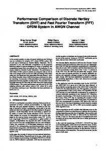
Fig. 11. GPS signal acquisition utilizing optimized FFT To further verify the advantages of processing efficiency with utilizing optimized FFT, compare the signal acquisition time in various Doppler shifts. The results are shown in Fig. 13, which indicate the processing efficiency of improved method has a significant superiority to the traditional methods.
www.intechopen.com
172
Fourier Transforms - Approach to Scientific Principles
Acquisition metric
15
10
5
0 0
5
10
15
20
25
30
PRN Number
(a) Acquisition results utilizing radix-2 algorithm
Acquisition metric
15
10
5
0 0
5
10
15
20
25
30
PRN Number
(b) Acquisition results utilizing improved algorithm Fig. 12. Acquisition results utilizing different algorithms
Average acquisition time (sec)
140 120 100 Radix-2 algorithm
80
Optimized algorithm
60 40 20 0 1
2
3
4
5
6
Doppler shift (kHz)
Fig. 13. Comparison of average acquisition time
www.intechopen.com
7
8
9
Optimized FFT Algorithm and its Application to Fast GPS Signal Acquisition
173
7. Conclusion and future work Apply an optimized FFT algorithm which integrates the traditional radix-2, radix-4, splitradix, PFA and WFTA to GPS C/ A code acquisition processing, and the primary results of simulation and experiment indicate that the optimized FFT algorithm could improve the average acquisition time and operation efficiency significantly. It is believed that this method could also be utilized in the long code acquisition, such as P code. Future work is to research and develop a more efficient and flexible processing platform to satisfy the demands of fast DFT calculation.
8. References D. Akopian. (2005). Fast FFT based GPS satellite acquisition methods, IEE Proceedings Radar, Sonar and Navigation, vol. 152, no. 4, pp. 277-286. D.J.R. Van Nee & A.J.R.M. Coenen. (1991). New fast GPS code-acquisition technique using FFT, Electronic Letters, vol. 27,no. 4, pp. 158-160. J. Jin, S. Wu, & J. Li. (2005). Implementation of a new fast PN code-acquisition using radix-2 FFT, Journal of Systems Engineering and Electronics, vol. 27, no. 11, pp.1957-1960. Elliott D. Kaplan, & Christopher J. Hegarty. (2006). Understanding GPS Principles and Applications (Second Edition), ARTECH HOUSE, INC., pp.113-152, Norwood. Michael S. Braasch , & A. J. Van Dierendonck. (1999). GPS receiver architectures and measurements, Proceedings of the IEEE, vol. 87, no. 1, pp. 48-64. C. Li, X. Zhang, H. Li, & Z. Zhang. (2008). Frequency-domain tracking method of GPS signals, Chinese Journal of Electronics, vol. 17, no.4, pp. 665-668. P. Duhamel, & M. Vetterli. (1990). Fast fourier transforms: A tutorial review and a state of the art, Signal Processing, vol. 19, no. 4, pp. 259-299. C. S. Burrus, & P. W. Eschenbacher. (1981). An In-Place, In-Order Prime Factor FFT Algorithm, IEEE Transactions on Acoustics, Speech, and Signal Processing, vol. 29, no. 4, pp. 806-817. N. B. Jones, & J. D. McK. Watson. (1990). Digital signal processing: principles, devices, and applications, Institution of Engineering And Technology, pp. 43-77, United Kingdom. D. Sundararajan. (2003). Digital signal processing: theory and practice, World Scientific Publishing Company, pp. 43-58, Singapore. W. L. Mao, W. H. Lin, Y. F. Tseng, H. W. Tsao, & F. R. Chang. (2007). New Acquisition Method in GPS Software Receiver with Split-Radix FFT Technique, 9th International Conference on Advanced Communication Technology, 722-727, February 2007, Phoenix Park, Korea. C. S. Nagaraj, G. D. Andrew, & R. Chris. (2009). Application of Mixed-radix FFT Algorithms in Multi-band GNSS Signal Acquisition Engines, Journal of Global Positioning Systems, Vol. 8, No. 2, pp. 174-186. S. Chu, & C. S. Burrus. (1982). A Prime Factor FFT Algorithm using Distributed Arithmetic, IEEE Transactions on Acoustics, Speech, and Signal Processing, vol. 30, no. 2, pp. 217227. B. Liu, & L.J. Zhang. (1997). An Improved Algorithm For Fast Fourier Transform, Journal of Northeast Heavy Machinery Institute, vol. 21, no. 4, pp. 296-300. Winogard S. (1976). On computing the discrete Fourier transform, Mathematics of Computation, vol. 73, no. 4, pp. 1005-1006.
www.intechopen.com
174
Fourier Transforms - Approach to Scientific Principles
W. H. Lin, W. L. Mao, H. W. Tsao, F. R. Chang, & W. H. Huang. (2006). Acquisition of GPS Software Receiver Using Split-Radix FFT, 2006 IEEE Conference on Systems, Man, and Cybernetics, pp. 4608-4613, October 2006, Taipei, Taiwan. L. Zhao, S. Gao, & Y. Hao. (2009). Improved Fast Fourier Transform Processing on Fast Acquisition Algorithms for GPS Signals, The Ninth International Conference on Electronic Measurement & Instruments, vol. 4, pp. 221-224, August 2009, Beijing, China.
www.intechopen.com
Fourier Transforms - Approach to Scientific Principles Edited by Prof. Goran Nikolic
ISBN 978-953-307-231-9 Hard cover, 468 pages Publisher InTech
Published online 11, April, 2011
Published in print edition April, 2011 This book aims to provide information about Fourier transform to those needing to use infrared spectroscopy, by explaining the fundamental aspects of the Fourier transform, and techniques for analyzing infrared data obtained for a wide number of materials. It summarizes the theory, instrumentation, methodology, techniques and application of FTIR spectroscopy, and improves the performance and quality of FTIR spectrophotometers.
How to reference
In order to correctly reference this scholarly work, feel free to copy and paste the following: Lin Zhao, Shuaihe Gao, Jicheng Ding and Lishu Guo (2011). Optimized FFT Algorithm and its Application to Fast GPS Signal Acquisition, Fourier Transforms - Approach to Scientific Principles, Prof. Goran Nikolic (Ed.), ISBN: 978-953-307-231-9, InTech, Available from: http://www.intechopen.com/books/fourier-transformsapproach-to-scientific-principles/optimized-fft-algorithm-and-its-application-to-fast-gps-signal-acquisition
InTech Europe
University Campus STeP Ri Slavka Krautzeka 83/A 51000 Rijeka, Croatia Phone: +385 (51) 770 447 Fax: +385 (51) 686 166 www.intechopen.com
InTech China
Unit 405, Office Block, Hotel Equatorial Shanghai No.65, Yan An Road (West), Shanghai, 200040, China Phone: +86-21-62489820 Fax: +86-21-62489821