Sensoren und Messsysteme ∙ 03. – 04.06.2014 in Nürnberg
Error Correction of Automatic Testing Systems for Hall Effect Current Sensors Cheng Liu, Ji-Gou Liu ChenYang Technologies GmbH & Co. KG., Markt Schwabener Str. 8, 85464 Finsing, Germany http://www.chenyang.de, Tel. +49-8121-2574100, Fax: +49-8121-2574101,
[email protected]
Abstract In this paper an error correction method is proposed for improving the measuring accuracy of automatic testing systems for Hall Effect current sensors. The errors of the original testing system are determined by a reference sensor or a reference resistor. These error values are saved as corrections into a data matrix in the testing system. The systematic errors of the testing system are corrected by using the correction data matrix. In this way a conventional measuring system can be enhanced into a precise measuring system. The proposed method can be used in all automatic testing systems. Keywords: Error Correction, Measuring Accuracy, Accuracy Improvement, Sensor Test, Hall Effect Current Sensor, Current Sensing, Automatic Testing System, Measuring System, Control System, Automation
1
lower than ±0.05%. Nevertheless, this criterion cannot be fulfilled for the most conventional current measuring systems. Therefore better and more accurate instruments are needed for testing the Hall Effect current sensors. However such precise instruments are much more expensive. It results in increasing testing costs of current sensors. This paper proposes an error correction method of automatic testing system for Hall Effect current sensors. This method consists of error determination and error correction. By using the proposed method the accuracy of the automatic testing system can be effectively improved and controlled within ±0.03%. Instead of buying expensive equipment, the error correction is a favorite solution for testing systems. The principle can also be applied to measurements of other electrical and physical quantities.
Introduction
Current sensing is an important operation for many electric power, driving and communication systems. Traditionally, it was primarily intended for circuit protection and control. With the technological advance, current sensing has appeared as a method for monitoring and performance enhancing. Therefore, current sensors are applied to power systems, current and voltage regulators, linear and switch-mode power supplies, inverters, rectifiers, motor drives, generators, automotive power electronics, electric powered locomotives, telecommunications, transformer substations, battery management systems, wind turbines and photovoltaic equipment etc. Hall Effect current sensors are preferred towards other competitive technologies like shunt resistors, because they provide many benefits such as wide measuring range, good linearity, high accuracy, Galvanic isolation between input and output, and wide variation of sensor configurations etc. [1, 2]. In order to achieve reliable results and to ensure satisfying quality, Hall Effect current sensors have to be tested before using. An automatic testing system can be very helpful to save the testing time. A simple automatic testing system for Hall Effect current sensors consists of three basic components: a digital multimeter (DMM), an AC/DC current source and a PC system. For a trustful quality control, it is important that the test equipment should be more accurate than the sensor under test. The measuring error of the testing system should be lower than one-fourth of the error of the sensor [3]. The most Hall Effect current sensors are defined with accuracy from ±1.0% to ±0.2%. So for testing all of these sensors, the measuring deviation of testing systems must be
ISBN 978-3-8007-3622-5
2
Test Equipment
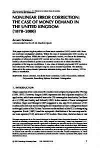
Figure 1 shows one of our automatic testing systems. It consists of a DMM (1), a DC current source (2), a PC system (3) and a data acquisition device with analog and digital outputs (4). The Agilent 34401A multimeter has a 6½ digit resolution. It provides many measurement functions (AC/DC voltage, AC/DC current, 2- and 4-wire resistance, diode, continuity, frequency and period) and has a basic accuracy 0.0035% for DC measurements and 0.06% for AC measurements [4]. The DC current source is an EA-PS 8080120. This device outputs a DC current of 0-120A. According to the data sheet, it has an accuracy ≤0.2% [5]. The NI USB-6008 is for data acquisition, but also offers two analog outputs and 12 digital I/O pins [6]. So it can be used for system controlling with software which runs on the PC system. Due to the deviations of the DC current source (±0.2%) and the DMM (±0.01%), the measuring
1
© VDE VERLAG GMBH · Berlin · Offenbach
Sensoren und Messsysteme ∙ 03. – 04.06.2014 in Nürnberg
deviation of the whole testing system is higher than 0.2%, which doesn’t fulfill the criteria for testing Hall Effect current sensors.
the output voltage Vsys for the same input current values. Thus, the absolute voltage deviation can be calculated by: (1) According to the given ratio k between output voltage and input current, the errors of the testing system ∆I can be determined by (2) The second method needs a reference resistance with high accuracy (±0.01%) and low temperature drift (< 10 ppm) (see figure 3). The error detection procedure in this case is comparable with the method above. The resistance has a value of 0.001Ω. The voltage Vm which can be measured is directly proportional to the input current (see figure 4). This voltage can be easily converted to the input current I m:
Figure 1 Components of Automatic Testing System
(3)
3
Error Correction Algorithm
The error of the testing system ∆I can be determined by the difference between measured current Im and the output current Io from the DC current source:
For improving measuring accuracy of measurement system, error compensation and correction methods can be used with the help of modern data processing methods [714]. Firstly, the errors of the measuring system have to be determined. There exist systematic and random errors [15]. The random errors can be reduced by signal processing. Systematic errors are caused by the inaccuracy of the system and can be determined and corrected. There are two methods for error determination of the testing system. The first method is using a reference current sensor (see figure 2). The output voltage Vref of this reference sensor is measured by a high precision measurement system with accuracy of ±0.01% in advance.
(4)
Figure 3 High Precision Reference Resistor
Figure 2 Error Determination with Reference Sensor For calibration, this reference sensor has been measured by testing system under correction again in order to get
ISBN 978-3-8007-3622-5
Figure 4 Error Determination with Reference Resistor
2
© VDE VERLAG GMBH · Berlin · Offenbach
Sensoren und Messsysteme ∙ 03. – 04.06.2014 in Nürnberg
In both cases the measured errors ∆I are saved as deviation data matrix in the PC system. The principle of the calibration is shown in the following figure 5.
where is a conversion factor. In order to perform the error correction, the absolute deviation can be simply multiplied with the linear factor and added to the original control voltage for getting a new control voltage
(
)
: (7)
By using , the current source is corrected and can give out a more accurate current output . The testing system can directly measure the current sensor output. In both cases, the measured values are saved with the current output ( ) on hard disk of the testing system for further processing. For calculating deviation values which are not listed in the data matrix, a linear interpolation can be used. Linear interpolation is processed in order to create new values between two known neighbor values. This method allows the use of less real measurement values and therefore less data space.
Figure 5 Determination of Deviation Data Matrix The deviation data matrix contains only the absolute deviations. By using this matrix, error correction algorithm can be performed for a testing system. Figure 6 shows the principle of a testing system with error correction algorithm.
4
Results
The rest errors after correction are mostly dominated by the random errors, because the majority of the systematic errors are compensated by the error correction algorithm. Moreover, with both error detection methods, the results are nearly the same. An accuracy of about ±0.03% can be reached. Table 1 shows the relative deviation of the testing system with the error correction algorithm in the range [0A, 120A]. Figure 7 visualizes the measuring results. Furthermore, it is also possible to make even small currents more accurate. Table 2 and figure 8 show the results in the range [0A, 5A]. Based on the above results, the testing system under using error correction can be defined with an accuracy of ±0.05% at least. It fulfills the criterion for testing and calibrating Hall Effect current sensors.
Figure 6 Testing System with Error Correction The error correction uses the deviation data matrix and linear interpolation for eliminating the systematic errors of the testing system. Concretely, the digital error correction is made by (5) where represents the current output before correction, the current deviation and the current output after error correction. Another way is to manipulate the control voltage of the current source if available. The control voltage V is proportional to the desired output of the current source, which can be set by the user under using a set current (ideally ): (6)
ISBN 978-3-8007-3622-5
Figure 7 Relative rest deviation in range [0A, 120A] of testing system after Error correction
3
© VDE VERLAG GMBH · Berlin · Offenbach
Sensoren und Messsysteme ∙ 03. – 04.06.2014 in Nürnberg
Current under test (A) 0 5 10 15 20 25 30 35 40 45 50 55 60 65 70 75 80 85 90 95 100 105 110 115 120
5
Relative deviation (%) -0,027 -0,009 -0,005 -0,021 0,002 -0,011 0,002 -0,015 0,003 0,015 -0,007 0,013 -0,011 -0,028 -0,003 0,004 -0,013 0,004 -0,013 0,019 -0,014 0,001 -0,024 -0,005 0,013
The proposed error correction algorithm is tested on our current sensor testing system with EA-PS 8080-120 and Agilent 34401A. From the test results one can draw the following conclusions:
Table 1 Relative rest deviation in range [0A, 120A]
Figure 8 Relative rest deviation in range [0A, 5A] Current under test (A) 0 0,5 1,0 1,5 2,0 2,5 3,0 3,5 4,0 4,5 5,0
Relative deviation (%) -0,003 -0,020 -0,005 0,006 -0,007 -0,017 -0,011 -0,020 0,002 -0,006 0,006
6
For testing Hall Effect current sensors, the measurement system needs at least an accuracy of ±0.05%. High precision systems are more expensive. It results in higher testing costs for sensors. The error correction algorithm contains two parts: error determination and error correction. The measuring error of a testing system can be determined with a reference sensor or resistor. The reference sensor should be measured with a high precision measurement system in advance. The reference resistor should have a high accuracy and a low thermal drift. The absolute deviations of the inaccurate system are saved as a deviation data matrix in PC system for error correction. During the error correction, the deviation data matrix is used to compensate the systematic errors of the testing system. Linear interpolation can be used for getting a deviation value between two known neighbor values. In this way the data space can be saved. Testing system under correction can be improved to an accuracy of about ±0.03%. It fulfills the criterion for testing current sensors. The error correction algorithm offers a low-cost solution for improving the measuring accuracy of existing testing systems. It is very suitable for different testing systems and can be easily integrated in custom software. This principle can also be applied to measurements of other electrical and physical quantities.
References
[1] E. Ramsden: Hall Effect Sensors – Theory and Application. Amsterdam, London, New York etc.: Elsevier Inc., 2006 [2] J.-G. Liu, A. Sanli, Y. Wang, C. Liu: Error Compensation of Closed Loop Hall Effect Current Sensors. 2012 IEEE International Workshop on Applied Measurements for Power Systems (AMPS), Aachen, Germany, September 26-28, 2012 [3] M. Cable: Calibration: A Technician's Guide. ISA – Instrumentation, Systems, and Automation Society, 2005
Table 2 Relative rest deviation in range [0A, 5A]
ISBN 978-3-8007-3622-5
Conclusions
4
© VDE VERLAG GMBH · Berlin · Offenbach
Sensoren und Messsysteme ∙ 03. – 04.06.2014 in Nürnberg
[4] Data Sheet Agilent 34401A Multimeter: http://cp.literature.agilent.com/litweb/pdf/59680162EN.pdf [5] Data Sheet EA-PS 8000 2U: http://www.elektroautomatik.de/fileadmin/pdf/datash eets/datasheet_ps8000-2u.pdf [6] User Guide and Specifications NI USB-6008/6009: http://www.ni.com/pdf/manuals/371303m.pdf [7] J.-G. Liu: Verbesserung der Messgenauigkeitin rechnergesteuerten Mess- und Prüfsystemen. Technisches Messen, tm 9/2002, pp.390-398 [8] J.-G. Liu, U. Frühauf: Self-Calibration Measuring Methods and Application to Measurements of Electrical Quantities. Measurement, vol. 26, no.2, August 1999, pp. 129-141 [9] H. Heuermann, B. Schiek: Error corrected impedance measurements with a network analyzer. IEEE Trans. Instrum. Meas. 44 (2) (1995) 295-299 [10] G. Adria, M. Savino, A. Trotta: Windows and interpolation algorithms to improve electrical measurement accuracy. IEEE Trans. Instrum. Meas. 38 (4) (1989) 856-863 [11] J.-G. Liu, U. Frühauf, A. Schönecker: Accuracy Improvement of Impedance Measurements by Using the Self-Calibration. Measurement, Vol. 25, no. 3, April 1999, pp. 213-225 [12] J.-G. Liu, A. Schönecker, U. Frühauf, U. Keitel, H.J. Gesemann: Application of discrete fourier transform to electronic measurements. Proceedings of the First International Conference on Information, Communications & Signal Processing 3 (1997) 1257-1261 [13] M. Sedlacek, M. Titera: Increased accuracy Measurement of parameters of non-synchronously sampled periodic signals. IMEKO TC4 Symposium on Development in Digital Measuring Instrumentation and 3rd Workshop on ADC Modelling and Testing, Naples, Italy, vol. I, 1998, pp. 169-173 [14] J.-G. Liu, A. Schönecker: Recursive self-correction algorithm of discrete Fourier transform and application to electrical measurements. 43rd International Scientific Colloqium, Ilmenau, Germany, September 21-24, 1998, pp. 515-520 [15] E. Schrüfer: Elektrische Messtechnik – Messung elektrischer und nichtelektrischer Größen, 6th Edition. Carl Hanser Verlag Munich, 1995
ISBN 978-3-8007-3622-5
5
© VDE VERLAG GMBH · Berlin · Offenbach