Error Resilient Coding Based on Reversible Data Embedding Technique for H.264/AVC Video Wen-Nung Lie, Tom C.-I. Lin, Dung-Chan Tsai, and Guo-Shiang Lin Department of Electrical Engineering National Chung Cheng University, Chia-Yi, 621, Taiwan, ROC. Phone : 886-5-2720411 ext. 33211, Fax : 886-5-2720862 E-mail :
[email protected] ABSTRACT In this paper, a prescription-based error concealment (PEC) method is proposed. PEC relies on pre-analyses of the concealment error image (CEI) for I-frames and the optimal error concealment scheme for P-frames at encoder side. CEI is used to enhance the image quality at decoder side after error concealment (by spatial interpolation or zero motion) of the corrupted intra-coded MBs. A set of pre-selected error concealment methods is evaluated for each corrupted inter-coded MB to determine the optimal one for the decoder. Both the CEI and the scheme indices are considered as the prescriptions for decoder and transmitted along with the video bit stream based on a reversible data embedding technique. Experiments show that the proposed method is capable of achieving PSNR improvement of up to 1.48 dB, at a considerable bit-rate, when the packet loss rate is 20%.
I. INTRODUCTION H.264/AVC is the newest and most efficient (50% savings in bits with respect to the best before) international video coding standard up to now. However, as the video data are highly compressed, they become sensitive to errors caused by unreliable transmission channels. Errors in bits will make following VLC codes undecodable until a re-synchronization code is met. Corruption or loss of packets also leads to error propagation in temporal direction, due to motion-compensated coding structure in most video standards. Henceforth, the received video bit stream would result in a poor visual quality. To reduce quality degradation, many error resilience/ concealment methods (such as inserting resynchronization markers, reversible variable length coding (RVLC), and error resilient entropy coding (EREC)) were proposed to resist channel errors and recover the corrupted frames [1, 2]. Recently, several error resilient video coding methods based on data embedding techniques were proposed. They applied data embedding schemes to establish another covert channel for transmitting important information that enhances error resilience capability without increasing the bit-rate significantly [3-8]. In [3], the parity check bits of motion vector (MV) code words in a frame are embedded into the half-pel MVs of its following frame to recover the corrupted MVs with a single bit error. This embedding (as noise) however degrades the video quality by 0.3~1.0 dB of PSNR. The method of parity embedding error detection (PEED) [4], on the other hand, embeds parity check bits of macroblock (MB) data into MVs and DCT coefficients of the following frame. PEED is capable of detecting errors, but leaves bits between the synchronization code and the error bit to be discarded even thought they are error-free. In [5], a feature vector containing information such as smoothness, edge orientation code, etc., is computed for each encoded MB and embedded into its companion counterpart. These features are thus extracted at the decoder to facilitate error concealment, especially for the interpolation of intra-coded MBs. In [6], Leou et al. proposed to embed codeword indices,
0-7803-9332-5/05/$20.00 ©2005 IEEE
generated by vector quantization (VQ) technique, of an image into the JPEG quantized DCT coefficients by the modulo 2 method. At the receiver, the VQ information is extracted to reconstruct the corrupted blocks in presence of channel errors. In [7], Okada et al. proposed to embed the so-called check marker of each MB into its own DCT coefficients. This method provides better error detection capability than the traditional MPEG-4 decoder, but still has to discard bits between the error bit and next synchronization code. Robie et al. [8] proposed to embed the MB bit length information to aid MB resynchronization. In this way, spatial error propagation could be effectively limited within the MB where errors occur. Though useful information can be transmitted via data embedding techniques to recover errors at the decoder side, the accompanying quality degradation in error-free condition makes tradeoffs to be made for this kind of methods. It is normally expected that more embedded information will result in more error resilience and larger quality degradation simultaneously. Recently, some reversible data hiding schemes have been proposed [9,10]. By using these hiding schemes, the hidden data can be correctly extracted, with full recovery of the original image data at decoder side. That is, the decoded image quality can be maintained as good as in case that no information is embedded. This motivates us to integrate the reversible data-hiding scheme in error resilient video coding. Here, a prescription-based error resilient coding method is proposed. A prescription is meant to be a set of instructions for error concealment, which are analyzed out at the encoder side. For I- and P-frames, the prescriptions contain different kinds of information, due to their difference in coding principle. Since the prescription is obtained at the encoder side with the original image data at hand, a certain extent of optimality could be ensured. The prescription is then transmitted to the decoder via the above-mentioned reversible data-hiding scheme.
II. ARCHITECTURE OF PRESCRIPTIONBASED ERROR CONCEALMENT (PEC) Traditional error concealment techniques focus on exploring information from spatially or temporally neighboring frames or MBs (which are error free) to recover the error parts in current frame or MB. Most of the efforts are made by decoder. Obviously, the decoder does not know what the truths are in presence of corrupted data and only pre-fixed concealment steps will be performed for error recovery. A pre-fixed error concealment step is advantageous of its simplicity, but suffers from blindness and poor adaptation to image contents. If a diagnosis step is performed in advance and a prescription for error recovery/concealment is issued accordingly at encoder side, the end-to-end distortions in presence of channel errors can then be eliminated as possible. We, however, face the problem of how to transmit the prescriptions to the decoder in an efficient way. Data embedding may act as the bridge in this research. The prescription content constitutes another important issue. It is well known that for corrupted MBs in P-frames, MV information can be estimated or predicted from neighboring
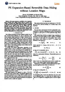
error-free MBs and most of the lost MB information can be recovered from this estimated MV. Error concealment of P-frames hence reduces to a MV recovery problem. On the other hand, most of the prior techniques use spatial interpolation or inheritance from the previous frame. Both the above-mentioned techniques for I- and P-frames are not sufficient to support high quality videos. Here, our prescription will contain extra information for decoders than what they can do alone. For I-frames, a CEI (Concealment Error Image), calculated from the difference between the normally reconstructed frame (in error-free condition) and the errorrecovered frame (e.g., via spatial interpolation or zero motion), is obtained at encoder. CEI can be transmitted to the decoder side and used to enhance the quality of error recovery. However, the CEI data are too bulky to be transmitted. Only important parts are retained and transmitted via data embedding technique. Here in this paper, the CEI is first wavelets-transformed and significant coefficients are then selected for embedding and transmission. For P-frames, there were several methods proposed for MV recovery, but none of them is suitable to all kinds of images. Since raw image data are available at encoder side, it is possible to conduct an exhausted evaluation for a limited selection of methods and determine the optimal one (ignoring the error propagation effect in evaluation) that should be performed at decoder side. The indices of optimal methods for all MBs in a frame are then encoded as a binary bit sequence and embedded by using a reversible data-hiding scheme. At the decoder side, the inverse embedding procedure is performed to reconstruct the host DCT coefficients and extract the embedded data. By using the reversible data-embedding scheme, the host DCT coefficients can be fully reconstructed without distortions. Drawbacks of prior works [3-8], i.e., quality degradation in case of no channel errors, could hence be eliminated. Our Prescription-based error concealment (PEC) method is divided into three stages (Fig. 1): 1) diagnosis stage (encoder side): evaluation of important information as the prescription, 2) prescription stage (encoder side): embedding of the prescription, and 3) remedy stage (decoder side): error concealment according to the received prescription.
Fig.1 Architecture of Prescription-based Error Concealment (PEC) method.
III. REVERSIBLE DATA EMBEDDING Traditionally, the researchers would explore data embedding schemes that would cause least distortions of the host signals. On the other hand, the reversible data-embedding scheme [10] is featured of the capability to fully reconstruct the host data with no distortion or quality degradation. In [10], a scheme based on difference expansion was proposed in the spatial domain. Here, we apply it in the quantized DCT domain to embed information introduced in Section II. To be conformed to H.264 standard, one 4×4 DCT block is used to carry one bit of information. Two quantized coefficients ( f1 o , f 2o ) therein are selected and modified to carry a message bit m whose value is 0 or 1: f 1 h = f − w2 d h , (1) h f 2 = f + w1 d h
where f1 h and f 2h represent the modified coefficients, f is a weighted sum of
f1 o and
f 2o (i.e.,
f = w1 f1o + w2 f 2o ,
w1 + w2 = 1.0 ), the modified difference d h (d h = 2d o + m) is
obtained by expanding the original difference d o = f1 o − f 2o , and
⋅
and
⋅
denote the ceiling and floor functions,
respectively. As shown in Eq. (1), we can adequately adjust w1 and w2 to keep a higher visual quality after data hiding. In the extraction procedure, the message bit m can be determined from the modified coefficients, f1 h and f 2h , via the equation m = d h mod ulo 2 , where d h = f1 h − f 2h . To reconstruct
the original host DCT coefficients, the weighted sum
f
( f = w1 f1 + w2 f 2 ) and the original difference d = d / 2 are first calculated and then perform: h
h
f 1 o = f − w2 d o . o f 2 = f + w1 d o
o
h
(2)
Normally, the weights w1 and w2 are chosen based on some other requirements, such as quality degradation, etc. Here, we set both weights to be 0.5. Aside from the issue of perfect reconstruction of original host DCT coefficients, variation of resulting bit-rate is another concern. To this end, the host coefficients are chosen to be in the low-frequency band to avoid interfering with the “zero” runs. In current implementation, the first two AC coefficients in the zigzag order are chosen in each 4×4 DCT block.
IV. DETAILED THREE-STAGE PROCESSING OF PEC A. Diagnosis stage
Essentially, schemes for error concealment depend on several considerations, e.g., types (I, P, or B) of the coded frame, geometrical relation between the corrupted and the correctly received MBs, the information that can be retrieved at decoder, etc. The last two issues are what the encoder can control. Normally, we prefer the corrupted MBs be distributed or even isolated so that enough error-free information can be obtained from adjacent MBs. Consider the common case that the video bit stream is transmitted in terms of packets. Each packet can be organized as a set of MBs: a slice in MPEG or a GOB (group of blocks) in H.263+. The H.264 standard provides a manner of flexible MB ordering (FMO) to enhance its error resilience capability. FMO allows assigning MBs to slices in a specific order, such as “box in” or “checker board”, or in the form of an arbitrary slice group map [12]. Among them, the checker-board scanning order is beneficial of maximizing available reference information from neighboring MBs for error concealment. For packetization, each I-frame and P-frame is divided into six and two packets, respectively, according to their size statistics. In other words, each packet contains one sixth number of MBs for I-frames or a half number of MBs for P-frames. Once a packet is lost, the error concealment mechanism replenishes missing MBs by using information from the 4-neighborhood MBs. As mentioned above, for P-frames, the encoder evaluates several error concealment methods and determines the best one for each MB. Herein, seven schemes are pre-chosen as the recipes, which can be categorized into two classes: temporal and spatial domains. They are listed as follows. (1) Zero motion vector (ZMV): replace the corrupted MB with the MB which is at the same location of the previous frame. (2) Previous motion vector (PMV): replace the corrupted MB
with the area indicated by the MVs of the MB (may be multiple, depending on the result of mode decision and multiple references) which locates at the same position in the previous frame. (3) Average motion vector (AMV16): replace the corrupted MB with the area indicated by the MV which is taken by averaging MVs from the top, left, and temporal (same position in previous frame) neighboring MBs. If there are multiple MVs existing in a neighboring MB, they are all taken into considerations in an area-weighted averaging process. (4) Average motion vector (AMV4): similar to AMV16, but the MV estimation is targeted at each 4×4 block of the corrupted MB. Note that the MV estimation is recursive in a causal manner (i.e., from top to bottom and from left to right). (5) Median motion vector (MMV16): replace the corrupted MB with the area indicated by the MV which is taken by getting the median of the MVs from the top, left, and temporal neighboring MBs. If there are multiple MVs existing in a neighboring MB, they are all taken into considerations in an area-weighted median process. (6) Median motion vector (MMV4): similar to MMV16, but the MV estimation is targeted at each 4×4 block of the corrupted MB. Note that the MV estimation is recursive in a causal manner (i.e., from top to bottom and from left to right). (7) Spatial interpolation (SI): replenish pixels in a corrupted MB via interpolation from pixels in neighboring decoded MBs. Since the checker board slicing structure is used in the proposed system, the four-neighborhoods MBs (top, bottom, left, and right) are located in another correctly received packets and can be used as the references for spatial interpolation. The recovered MB is represented as MB(i, j) =
1 [dL ⋅ MBR (i,15) + dR ⋅ MBL (i,0) + dT ⋅ MBB (0, j) , dL + dR + dT + dB
(3)
+ d B ⋅ MBT (15, j)]
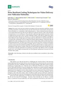
where MBL, MBR, MBT and MBB represent the left, right, top and bottom neighborhing MB, i and j are pixel indices in the horizontal and vertical directions, respectively, and dL, dR, dT, and dB are distances from the neighboring MBs to the interpolated pixel. The geometrical relations are shown in Fig. 2.
Fig. 2 Geometrical relations for MB-based pixel-domain spatial interpolation. The sum of absolute difference (SAD) between the recovered and the raw MB data is used as the criterion for choosing the best scheme among the seven schemes for error concealment at decoder. Clearly, three bits are required to represent the chosen scheme. Only the first I-frame in the whole sequence is spatially interpolated if packet losses occur. For following I-frames, zero motion technique is applied for error concealment. The result of error concealment and the received CEI are combined for error recovery. For efficient transmission of CEI, it is first wavelets-transformed and then coefficients in certain important bands are selected. As shown in Fig.3, after four levels of decomposition, each pixel of the subband images at the highest level represents a 16×16 MB in the original image. The three detailed subbands at the highest level (the shaded parts in Fig.3)
are selected as the recipes for error concealment at decoder. Since the embedding capacity is finite, the selected wavelets coefficients are non-uniformly quantized and assigned with a corresponding index (3-bit) listed in Table I.
Fig. 3 Four-level wavelets transformation of CEI. The subbands with oblique lines are selected as recipes. Table I the index table for wavelet coefficient Wavelets coefficient (value) value < -70 -30 > value>= -70 -10 > value>= -30 0 > value>= -10 10 > value>= 0 30 > value>= 10 70 > value>= 30 value > 70
Index 0 1 2 3 4 5 6 7
In summary, the recipe for each MB in I- and P-frames requires 9 bits (3*3=9, corresponding to 3 details subbands in Fig.3) and 3 bits, respectively. B. Prescription stage
To prevent delay, the recipes are embedded in another packet of the same frame. Since the checker-board slicing is used, recipes of the MBs sliced to the black set are embedded into the MBs sliced to the white set. Since a 16×16 MB contains sixteen 4×4 blocks, the embedding capacity is at least 16*n bit, where n is the number of bits embedded in a 4×4 block. For zero 4×4 blocks, they cannot be used as the host blocks for data embedding. Therefore, recipes of MBs are scanned in the manner shown in Fig. 4 and then embedded. Henceforth, recipes of the MBs around the image boundary may be abandoned if the embedding capacity is not enough.
Fig. 4 Spiral scanning order of recipes for embedding and transmission. C. Remedy stage
At the decoder side, the two DCT coefficients selected to embed one bit information in each 4×4 block should be converted to recover their original values (by Eq.(2)) and extract the embedded information, disregarding the status (corruption or not) of the MB whose recipe is represented by them. As the error detection mechanism detects packet loss or corrupted MBs, the decoder looks up the recipes and recovers the corrupted MBs according to the instructions therein. For I-frames, spatial interpolation or zero motion is first used to replenish the corrupted MBs and then the extracted recipes are used to enhance the recovered result. On the other hand, each corrupted MB in P-frames is replenished with the method indicated by the recipe.
V. EXPERIMENTAL RESULTS Our experiments were preformed on 4 CIF 4:2:0 color video sequences (each 150 frames) coded at 30 fps (frames per second) by using H.264 reference software JM9.2. Each group of pictures (GOP) is structured as IPPP… and contains 15 frames. The target bit rate is set to 512 kbps (except “Mobile” which is more complex and thus set to 1.0 Mbps). The rate control function of JM9.2 is enabled, with every 22 MB (i.e., one row) having the same quantization step size (QP), so that the encoded bit streams of traditional and PEC-based have an approximately equal bit rate (below 0.1% of imprecision). For error simulations, we assume that each packet contains 1/6 and 1/2 numbers of MBs for I- and P-frames, respectively. Different packet loss rates (PLR) are simulated and each is repeated five times with randomness. Table II shows our PSNR Gains with respect to the best fixed-mode method (the bolded one). Our method provides an average improvement of -0.01 dB, 0.09 dB, 0.24 dB, and 0.5 dB for PLR equal to 1%, 5%, 10%, and 20%, respectively, at an approximate bit rate. At a higher PLR, our algorithm has a higher gain. For error-free situation (i.e., PLR=0%), our PSNR may be slightly worse than that without embedding (by 0.0 ~ 0.3 dB). This is not caused directly by reversible data embedding, but due to disturbances to efficiency of CABAC coding. This means that there is still a space of improvement to cope with the influence of data embedding on resulting bit rate. It is observed that for static videos such as “Container”, PEC is worse than the best fixed-mode method. This is reasonable since information transmitted via prescription does not play a key role in error concealment at decoder, but contrarily waste a few overheads in bit rate. It should be noticed that although PMV seems to override other fixed-mode methods in terms of average PSNR in most of the cases, it may not be so for other cases. Besides, the prescription provided by PEC is absolutely optimal for each MB (not in average sense), hence there are still gains with respect to the PMV method. This is why we try to adopt a prescription-based method, instead of a fixed one.
VI. CONCLUSIONS In this paper, a prescription-based error concealment method based on reversible data embedding technique, is proposed. The prescription is based on a pre-analysis of CEI and optimal error concealment methods for I and P-frames, respectively, at encoder side. PEC then transmits the prescriptions by using a reversible data-embedding scheme, which is characterized of the capability to fully reconstruct the host coefficients after data extraction. Though experiments show that PEC has a PSNR improvement of up to 1.48 dB with respect to the best fixed method when PLR is equal to 20%, the inefficiency in caused bit rate resulting from data embedding is still the most important issue to be improved in the near future.
RRFERENCES [1] [2] [3] [4] [5]
M.-T. Sun and A. R. Reibman, Compressed Video over Network, Marcel Dekker, Inc. New York, Basel, 2001 M. E. Al-Mualla, C. N. Cabagarajah, and D. R. Bull, Video coding for mobile communications, 2002 J. Song and K.J.R. Liu, “A data embedded video coding scheme for error-prone channels,” IEEE Trans. On Multimedia, vol. 3, no. 4, pp. 415-423, Dec. 2001. ISO/IEC JTC1/SC29/WG11 MPEG99/N6340, “An Error Detection Scheme using Data Embedding for H.263 Compatible Video Coding,” July 2000. P. Yin, B. Liu, and H. H. Yu, “Error concealment using
data hiding,” in Proc. of IEEE Int’l Conf. Acoustic, Speech and Signal processing, pp. 1453-1456, 2001. [6] L.W. Kang and J. J. Leou, “A new error resilient coding scheme for JPEG image transmission based on data embedding and vector quantization,” in Proc. of IEEE Int’l Conf. on Circuits and Systems, 2003 [7] H. Okada, A.E. Shiitev, H.S. Song, G. Fujita, T. Onoye, and I. Shirakawa, “Error detection by digital watermarking for MPEG-4 video coding,” IEICE Trans. Fundamentals, vol. E85-A, no. 6, pp. 1281-1288, 2002. [8] D. Robie and R. Mersereau, “Video error correction using steganography,” EURASIP Journal on Applied Signal Processing, pp. 164-173, Feb. 2002. [9] C. D. Vleeschouwer, J.-F. Delaigle, and B. Macq, “Circular Interpretation of Bijective Transformations in Lossless Watermarking for Media Asset Management,” IEEE Trans. Multimedia, vol. 5, no. 1, pp.97-105, 2003 [10] J. Tian, “Reversible Data Embedding Using a Difference Expansion,” IEEE Trans. Circuits Syst. Video Technol., vol. 13, no. 8, pp.890-896, 2003. [11] W. J. Chen and J.-N. Hwang, “The CBERC: a content-based error-resilient coding technique for packet video communications,” IEEE Trans. Circuits and Syst. Video Technol., vol. 11, no.5, pp.974-980, Aug .2001. [12] T. Wiegand, G. Sullivan, and A. Luthra, “Draft ITU-T Recommendation and Final Draft International Standard of Joint Video Specification,” ISO/IEC JTC1/SC29/ WG11 and ITU-T SG16 Q.6
Table II PSNR comparisons between PEC and fixed error concealment methods under different PLRs. PLR (%) Proposed 0 38.2 1 36.49 34.98 foreman 5 10 33.34 20 31.35 0 31.17 1 29.94 mobile 5 28.41 10 27.01 20 24.84 0 33.04 1 32.33 table 5 30.55 tennis 10 28.99 20 26.51 0 40.52 1 37.2 container 5 37.15 10 36.77 20 35.15
Zero 36.34 33.85 31.93 29.48 29.91 27.41 25.41 22.57 32.04 29.37 27.29 24.08 37.18 37.28 36.88 34.03
PSNR (dB) PMV AMV 38.46 36.48 36.36 34.1 34.64 32.89 32.24 29.9 30.67 31.49 30.18 30.04 28.41 28.03 26.96 26.42 24.55 24.07 33.04 32.16 32.09 30.08 29.69 27.7 28.14 25.02 24.72 40.84 37.1 37.19 36.72 37.6 37.18 36.11 35.58 33.46
MMV
Gain
36.29 34.06 32.44 30.27
0.01 0.34 0.45 0.68
30.06 28.1 26.51 24.19
-0.24 0 0.05 0.29
32.12 29.92 27.99 25.03
0.17 0.47 0.85 1.48
37.15 36.62 36.29 33.97
0.01 -0.45 -0.41 -0.43