Estimation of sub-module capacitor voltages in Modular Multilevel Converters Salvatore D'Arco* *SINTEF Energy Research 7465 Trondheim, Norway Salvatore.D'
[email protected]
Jon Are Suul*† Department of Electric Power Engineering Norwegian University of Science and Technology 7495 Trondheim, Norway
[email protected] †
Acknowledgements The work of SINTEF Energy Research in this paper was supported by the project "Protection and Fault Handling in Offshore HVDC Grids," (ProOfGrids), financed by the Norwegian Research Council's RENERGI program and the industry partners (EDF, GE, National Grid, Siemens, Statkraft, Statnett, Statoil and NVE) http://www.sintef.no/Projectweb/ProOfGrids/.
Keywords «Multilevel converters», «Converter control», «Estimation technique»
Abstract This paper presents a method for estimating the voltages at the individual sub-module capacitors of Modular Multilevel Converters (MMCs). The estimation method is designed according to a predictorcorrector scheme with a model-based prediction stage utilizing the arm current measurements and the internal modulation signals of the control system. The corrector stage is based on measurement of the total output voltage from each arm of the MMC. Thus, only two voltage measurements for each phase of the MMC must be continuously processed by the control system instead of individual voltage measurements for each sub-module. This can significantly reduce the communication requirements for the MMC control system and by that simplify the implementation. The principles of the proposed estimation method are described in detail in the paper, and the operation is demonstrated by simulation results. Estimation accuracy and settling time of the proposed method have been investigated with respect to the number of sub-modules in each arm of the MMC. Quantization effects due to limited resolution of the arm voltage sensors and the influence of parameter deviations have also been considered. The presented results illustrate the response of the proposed algorithm and indicate its potential for limiting the communication requirements and increasing system reliability by reducing the control system dependency on individual sub-module capacitor voltage measurements.
Introduction The Modular Multilevel Converter (MMC) has emerged as one of the most promising converter topologies for high voltage and high power applications. Since the basic topology was proposed by Lesnicar and Marquardt in [1] and [2], the MMC has been the object of significant research and development efforts. The modularity and scalability of this topology, allowing for high voltage applications with very high number of voltage levels in the AC output waveform by series connection of standardized low-voltage sub-modules, has made the MMC especially attractive for HVDC transmission and power system applications [2], [3]. Commercial applications of this topology have developed quickly, with the first large-scale MMCs for HVDC transmission and reactive power compensation commissioned already in 2009/2010 [4]. Point-to-point HVDC systems reaching 2x1000 MW at 320 kV DC are currently under planning with expected commissioning in a few years. MMCs have also become the preferred choice for large offshore wind farms with HVDC transmission under construction or planning in Europe [5], and are expected to become main elements in the development of future multi-terminal HVDC grids [6].
Each sub-module of an MMC consists of a capacitor with a half-bridge (or a full-bridge) structure as the interface to the input terminals. Balancing of the individual sub-module capacitor voltages, and control of the internal circulating currents, are important for reliable and efficient operation of a MMC [7]-[11]. Most algorithms designed for achieving these tasks rely on real-time measurements of the individual capacitor voltages [1], [12], [13]. For high power converters with several hundreds of submodules, the collection and processing of these voltage measurements can be a significant challenge. Furthermore, the high number of sensors and signals will influence both the cost and complexity of the control system hardware as well as the reliability of the overall system. A method for open loop estimation of the total stored energy in each arm of an MMC was proposed in [14] and [15], for achieving accurate modulation and control of the internal dynamics without processing a large number of measurement signals at a high sampling rate. This approach avoids the use of measured capacitor voltages as feedback signals for the modulation and internal control loops by assuming perfect balancing of the sub-module voltages and using voltage estimates calculated from the energy balance of the converter. However, individual sub-module voltage measurements are still needed for implementing the sorting algorithm for capacitor voltage balancing. Considering that the voltage balancing can be executed at a lower sampling rate than the modulation and the control of the converter currents, the approach proposed by [14], [15] allows for high performance control of the MMC with reduced requirements for high-speed real-time communication. By estimating the individual sub-module capacitor voltages, the dependency on a high number of voltage measurements could be avoided and the complexity of the MMC control system implementation could be significantly reduced. If cost and complexity are not the main concerns, such estimation can instead be used to improve the reliability of the control system with respect to sensor or communication failures. A simple method for estimating sub-module capacitor voltages of MMCs will therefore be presented in this paper. The proposed estimation method utilizes the gate signals from the modulation together with the measured arm currents and the total output voltage of the arm. Thus, all the sub-module capacitor voltage measurements of a three-phase MMC can be substituted by six voltage sensors measuring the output voltage of each arm. These voltage sensors must be rated for the full DC-voltage of the converter, and must have sufficient bandwidth and resolution to accurately represent the sum voltage of the connected sub-modules. Although this might be a challenge from the hardware point-of-view, it is assumed to be feasible, although practical implications are left for future studies. Therefore, the focus of this paper will be on development and analysis of the proposed estimation method, with preliminary verification of its performance under various operating conditions by time-domain simulations.
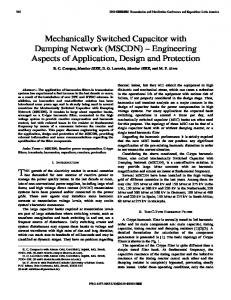
Modelling and control of Modular Multilevel Converters The reference structure of a three-phase MMC is shown in Figure 1, where the series connection of N identical sub-modules and a filter inductor constitutes one arm. Each sub-module usually contains a capacitor and a half-bridge structure, as shown to the upper right of the figure. Thus, the capacitor of each sub-module can either be inserted in the arm by turning on the upper switch, or it can be bypassed by turning on the lower switch [1], [2]. One phase leg is formed by two converter arms, with the upper and lower arms connected to the positive and negative DC-terminals respectively with the AC output in the mid-point. The MMC in the figure is shown with two series connected capacitors on the DC-bus to indicate the DC midpoint, although a central DC capacitor is not necessarily required.
Principles of MMC Operation In contrast to conventional two-level and multi-level voltage source converters, the MMC has continuously flowing currents in both the upper and lower arms. The output AC current is given by the instantaneous difference between the currents in the upper and the lower arms, according to the first part of (1). A circulating or differential current, idiff, can also be defined, and flows through the phase leg between the positive and negative DC-terminals, as given by the second part of (1). The DC component of this differential current can be directly associated to the average power transfer between the DC and AC side of the corresponding phase leg [7], [8].
Leg
Arm
iDC
iu ,a
iu ,b
A B
SM
B
A
2CDC
B
vdc ,u
vc ,u ,b
B
is ,a
B
A B
vdc ,l
iDC
SM
B
SM
B
il ,b
B
SM
AC source
is ,c
a b c
vg n
L A
SM
B
SM
A
SM
B
A
il ,a
C
A
L
A
A B
B
A
SM
SM
A
SM
L
A B
B
is ,b
L
SM
A
SM
L
m
2CDC
B
Submodule
A B
A
SM
L
vdc
SM
A
SM
A B
iu ,c
A
SM
A
SM
B
SM
il ,c
Figure 1 Structure of three-phase Modular Multilevel Converter
iu il (1) 2 Considering the output current is, as seen from the AC side of the MMC, the filter inductances of the upper and lower arms will be operated in parallel. The AC output current through these parallel connected inductors will be driven by an internal output voltage, vs, given by the upper and lower arm voltages, vc,u and vc,l, as expressed by (2) [7], [8], where the conduction losses of the filter inductor and switches in each arm is represented by a constant resistance R. vc ,u vc ,l L di R (2) vs vg s is 2 2 dt 2 The voltage driving the differential current is given by the difference between the total DC-link voltage and the voltages from the upper and lower arms. This differential voltage, driving the current through the series connection of the arm filter inductors, can be expressed by (3) [7], [8]. didiff vDC vc ,u vc ,l (3) vdiff L R idiff dt 2 Considering the sub-module topology shown in Figure 1, it can be seen that the capacitors of the inserted sub-modules will be charged or discharged by the arm current. The sub-module capacitor voltage will remain constant for bypassed sub-modules, which are not affected by the currents flowing in the arm. Thus, the voltage of sub-module i can be expressed by (4), where the gate signal or switching function gi is equal to 1 for inserted sub-modules and 0 for bypassed sub-modules. The arm annotation is omitted in this equation, since it is valid for both the upper and the lower arms. t 1 vc ,i t gi t i t dt vc ,i 0 (4) C0 is iu il ,
idiff
Modulation and capacitor voltage balancing for MMCs The modulation algorithm for an MMC should determine the number of sub-modules to be turned on in each arm, and the duty-cycle in case any of the sub-modules should be operated with Pulse Width Modulation (PWM). For this purpose, the insertion indices nu and nl for the upper and lower arms of the MMC can be defined according to (5), assuming equal voltages in all sub-module capacitors [7]. N v Number of inserted sub-modulesu ,l vc ,u ,l nu ,l vc,u ,l , vc,u ,l vc ,i ,u ,l , nu ,l c,u ,l (5) vc ,u ,l N i 1
This equation shows how the insertion indices express the share of sub-modules to be inserted. Thus they relate the actual voltage output reference vc to the available sum capacitor voltage vcΣ of the arm. Modulation methods for MMCs
The simplest modulation strategy for the MMC is to calculate the insertion indices assuming that all sub-module capacitor voltages are constant and equal to their rated average value of vDC/N [7]. For such open loop or "direct" modulation, the insertion indices are given directly by a modulation signal m for the AC output voltage according to (6), where −1 < m < 1. The voltage reference vs* used to generate the modulation signal can be the output of a conventional control system for output voltage or current, like for a traditional two-level or multi-level Voltage Source Converter. 1 m t 1 m t 2 v* t nu , nl , m t s,* (6) 2 2 vc ,u ,l The insertion indices in (6) can be used for MMCs with a high number of sub-modules as well as for converters with few sub-modules. For high numbers of sub-modules, "Nearest Level Modulation" (NLM) can be applied, resulting in a "staircase" output voltage with small steps. In systems with fewer voltage levels, PWM operation should be applied to one sub-module at a time per arm, to better reproduce the voltage reference. For such open loop PWM operation, the duty cycle signal for the submodule in PWM mode can be found directly from the fractional part resulting from multiplication of nu,l by N. With the direct modulation, neither the differential current of the MMC nor the sub-module capacitor voltages will be explicitly controlled, but the converter system will be self-stabilizing as long as the voltage oscillations of the capacitors are limited and the balancing of the sub-module voltages is assured. The differential current will be driven by the unbalance between the capacitor voltages of the upper and lower arms, which will have an average value depending on the power transfer between the DC and AC sides. A significant second harmonic distortion may also appear in the output voltages and currents, and there will be a large second harmonic component in the circulating current resulting from this mode of operation [16]. Closed loop modulation algorithms can be applied to improve the output voltage by compensating for the voltage variations of the sub-module capacitors. However, as discussed in [7], this will also require closed loop control of the sum voltage or stored energy in the upper and lower arms of the MMC by actively controlling the differential current. For simplicity, further considerations will be limited to the open loop modulation, since this can be considered as the worst case with respect to current and voltage waveforms in the MMC. Additionally, open loop modulation allows for studying the operation of the proposed estimation method without influence from the dynamics of any additional control loops operating on the capacitor voltages. Capacitor voltage balancing
The voltage balance among the sub-module capacitors of each arm must be maintained to ensure stable operation of the MMC structure. This is usually achieved by sorting the sub-modules according to the capacitor voltages and selecting the sub-modules to be turned on or off according to the current in the respective arm [1], [13]. For instance, if one additional sub-module is to be inserted and the arm current is in the direction that will charge the capacitors, the sub-module with the lowest voltage will be selected. Similarly, if the arm current is in the direction that will discharge the capacitors, the submodule with the highest voltage will be selected. The sorting can be done continuously if the capacitor voltages are available, but this might introduce additional switching operations that will improve the capacitor voltage balancing on the cost of additional switching losses. In most cases, it will be sufficient to carry out the sorting in a time range corresponding to half the AC fundamental frequency period to avoid unnecessary switching actions.
Proposed Estimation Algorithm For developing the proposed algorithm, it has been assumed that the individual arm voltages of the MMC can be measured directly between the upper or lower DC-bus and the corresponding filter inductor, as indicated for the upper arm of phase b in Figure 1.
Principle and structure of the proposed estimation algorithm The proposed estimation algorithm is based on a two-step procedure, with a simple predictorcorrector-like structure [17]. The first step of the estimation is a model-based prediction based on the sub-module capacitances, the measured current, the gate signals and the previously estimated voltage values. Then, this first estimate is corrected by processing the total arm voltage measurement. Prediction stage of the estimation
The estimation of the individual sub-module voltages starts from (4), considering a discrete time implementation with a sampling period of Ts . Thus, assuming that the voltage vc,i at the time tk is known, the predicted voltage at the time tk+1, can be expressed by (7). t 1 k 1 1 vcp,i tk 1 g i i dt vc ,i tk g i i Ts vc ,i tk (7) C tk C In this equation, the upper '~' indicates an estimated value, while the 'p' superscript indicates that the estimate is based on a prediction. For implementations with very short sampling period Ts, the gate signals and the sampled current measurements can be used directly in this equation. For operating the algorithm at lower sampling frequencies, the average values of the gate signals and the arm currents as defined by (8), can be used. This can be relevant if high speed processing of the measurements is available while the estimation algorithm is running at a lower sampling frequency. t t 1 k 1 1 k 1 (8) g i g i dt , i i dt Ts tk Ts tk The average of the gate signals will then be 0 for sub-modules that are bypassed during the entire sampling period, and will be equal to 1 for sub-modules that are inserted. If a sub-modele is operated in PWM mode, the average of the gate signal will be equal to the duty cycle of the upper switch in the sub-module. Thus, the value of g̅ i will be available from internal variables of the control system. The average value, ı̇̅ , for both the upper and the lower arm currents, can also be easily found by processing the current measurements already used for the closed loop current control. With the estimated sub-module voltages ṽi, at the time tk available from the estimation in the previous time step, the prediction of the voltage at time tk+1 from (7) can be rewritten as given by (9). Thus, the predicted arm voltage at the time tk+1 can be expressed by (10). 1 (9) vcp,i t k 1 g i i Ts vi t k C N
vcp tk 1 vcp,i tk 1 g i ,u tk 1
(10)
i 1
Correction stage of the estimation
The correction step of the estimation algorithm is based on the difference between the predicted arm voltage from (10) and the measured arm voltage. After redistributing the voltage error according to the duty cycle of the active sub-modules, the estimated voltages at time tk+1 can be expressed by (11). v p t vc ,u tk 1 vc ,i tk 1 vcp,i tk 1 c kN1 (11) g i tk 1 g i tk 1 i 1
By (11), the estimation is completed and the estimated capacitor voltages can be used for the sorting algorithm ensuring the voltage balance among the sub-modules in the same arm, for closed loop modulation, and for internal monitoring and protection within the control system. The estimated sum voltages of the upper and lower arm can also be easily calculated by: N
vc,u ,l tk 1 vc ,i ,u .l tk 1 i 1
(12)
Limitations and implementation requirements of the proposed estimation method The proposed estimation method can only operate on the sub-modules that are inserted. If for instance the sub-modules of the MMC are operated with a higher voltage then necessary for a given DCvoltage, or if there are redundant sub-modules, certain sub-modules may not be utilized for several cycles of the fundamental frequency. Thus, voltage errors in these sub-modules cannot be corrected before they are inserted and appear in the arm output voltage. From the practical point of view, the bandwidth and the resolution of the arm voltage sensors, which will have to measure the total arm voltages in the range between zero and the total sum capacitor voltage vcΣu,l, will be a critical factor for implementing the proposed estimation method The bandwidth requirement may be especially challenging, as the sensor bandwidth should be at least 5-10 times higher than the sampling frequency as long as nearest level modulation is considered. In case of PWM output from the MMC, the challenge of accurately measuring the arm voltage will be even higher if the intention is to accurately capture the voltage pulses. However, if the estimation algorithm is operated at lower sampling frequencies than the PWM frequency, it might be sufficient to apply analogue signal conditioning designed for approximately representing the averaging applied in (8) before the voltage signal is sensed. For intended operation of the estimation method, the Analogue to Digital Conversion (ADC) must also have sufficient resolution to accurately represent the required voltage range. The minimum number of bits nb of the ADC for a required resolution, resN, per sub-module is then given by (13). Assuming that a resolution of 15 levels is needed to detect a 10% variation in the individual sub-module capacitor voltages (i.e. 150 levels per sub-module), 16 bit ADC will be sufficient for an MMC with more than 200 sub-modules per arm. ln resN N nb floor (13) 1 ln 2
Simulation Results The operation of the proposed estimation method has been verified by using a model of a single phaseleg of an MMC converter in Matlab/Simulink with the main parameters given by Table I. The simulation model includes a simplified electrical model of each sub-module of the MMC, and the MMC leg is feeding a passive RL-load. The phase leg is operated by a simple control system including sorting algorithms and logics for selecting the inserted sub-modules as indicated in [1], [12].
Steady-state operation of the proposed algorithm A set of simulation results obtained with the parameters from Table I is shown in Figure 2 to illustrate the behaviour of the MMC leg and to verify the operation of the proposed estimation algorithm. The estimated sub-module voltages are used instead of measurements for the sorting and voltage balancing of the sub-module capacitor voltages. The phase output voltage vs, driving the AC current in the load, is shown in Figure 2 a), while the resulting phase current is in shown in Figure 2 b). A small second harmonic distortion can be noticed in the phase voltage and the phase current due to the open loop modulation. The resulting differential current idiff is shown in Figure 2 c) and it can be noticed that it has a DC component slightly below 250 A, corresponding to the 50 MVA load with power factor 0.95, and a second harmonic component with an amplitude of more than 700 A. The arm voltages and the arm currents are shown in Figure 2 d) and e) respectively. The sum capacitor voltages of both arms, corresponding to the maximum available voltages from the arms, are given in Figure 2 f). The plots in Figure 2 a-f) verify the expected steady-state operation of the MMC with the applied control system, without any significant influence of the estimation method. Table I Base case parameters for simulation of one leg of an MMC Rated power Sub-module capacitance Load
S = 100 MVA
DC-voltage
VDC = 200 kV
Number of levels
N = 20
C = 1 mF
Arm inductance
L = 30 mH
Arm resistance
R = 0.25 Ω
Sload = 50 MVA
Load power factor
cosφ= 0.95
Rated AC voltage
V̂ AC = 100 kV
Phase voltage
Phase current
Differential current 1200
100
1000
50
500
1000 800
0
-50
Current [A]
Current [A]
Voltage [kV]
600
0
400 200 0
-500
-200 -100
-400
-1000 0
0.01
0.02
0.03 Time [s]
0.04
0.05
0.06
0
a) Phase voltage, vs
0.01
0.02
0.03 Time [s]
0.04
0.05
-600
0.06
0
b) Phase current, is
Arm voltages
0.01
c)
0.02
0.03 Time [s]
0.04
0.05
0.06
Differential current, idiff
Arm currents
Sum arm voltages 240 Upper arm Lower arm
1000
230
200
220
500
100
Voltage [kV]
210 Current [A]
Voltage [kV]
150
0
-500
Upper arm Lower arm 0
0.01
0.02
0.03 Time [s]
0.04
0.05
170
-1000
0.06
0
d) Arm voltages, vc,u.l
0.01
e)
Sub-module capacitor currents
Voltage [kV]
Current [A]
500
0
-500
-1000 Sub-module 5 of upper arm Sub-module 15 of lower arm 0.02
0.03 Time [s]
0.04
0.03 Time [s]
0.04
0.05
160
0.06
Upper arm Lower arm 0
Arm currents, iu,l
0.01
0.05
g) Sub-module capacitor currents
0.06
12
11
11
10
9
8
8
0.01
0.02
0.03 Time [s]
0.04
0.04
0.05
0.06
0.05
7
0.06
h) Measured and estimated voltage of sub-module with correct capacitance value
Measured voltage of sub-module 15 in lower arm Estimated voltage of sub-module 15 in lower arm
10
9
0
0.03 Time [s]
Sub-module capacitor voltages 13
Measured voltage of sub-module 5 in upper arm Estimated voltage of sub-module 5 in upper arm
12
7
0.02
Sum arm voltages vcΣu,l
f)
Voltage [kV]
1000
0.01
0.02
Sub-module capacitor voltages 13
0
190 180
50
0
200
i)
0
0.01
0.02
0.03 Time [s]
0.04
0.05
0.06
Measured and estimated voltage of sub-module with 10% deviation of capacitance
Figure 2 Simulation results illustrating basic operation of the MMC and the proposed estimation method
Figure 2 g) shows the currents in one selected sub-module from the upper arm and one from the lower arm. In Figure 2 h) and i), the measured and estimated capacitor voltages for these two particular submodules are compared. For the sub-module in the upper arm, the capacitance values for the electrical circuit simulation and for the estimation algorithm are identical, and it can be noticed that the estimated value follows the measurement closely. For the sub-module in the lower arm, a 10% deviation in the capacitance value was introduced to verify the robustness of the estimation method with respect to parameter variations. Still, the voltage error is very small when many sub-modules are inserted in the lower arm, since the error is distributed among all the sub-modules. The maximum estimation error is occurring when there are few sub-modules inserted in the arm. However, this maximum error, which remains constant when the current is zero and the sub-module is not inserted, is smaller than the 10% deviation in the capacitance values.
Study of settling time and estimation errors Although it has been shown that the proposed algorithm operates as intended in stationary conditions, and that it can tolerate and suppress limited parameter deviations, the transient response is expected to depend on the number of sub-modules of the MMC. The transient response can also be influenced by the resolution of the voltage measurements as well as by deviations in the capacitance values. To analyze these effects, a Monte-Carlo approach for simulations has been applied, where numerical simulations have been repeated with randomly distributed initial conditions for the estimation algorithm. The maximum initial error of the sub-module voltages has been set to ± 30%, and the performance of the algorithm has been characterized by logging the average absolute error and the maximum absolute error of all the sub-modules in one phase leg of the MMC.
a) Average estimation error for a range of Monte-Carlo simulations with different number of levels per arm
b) Time response of the maximum estimation error among all simulations from Figure 3a)
Figure 3 Time response of average and maximum estimation error resulting from a series of Monte-Carlo simulations with randomly distributed initial estimation errors for various numbers of sub-modules per arm
Influence of the number of levels on the estimation accuracy and settling time
Six cases with between 20 and 200 sub-modules per arm have been examined to investigate the influence of the number of sub-modules of the MMC on the performance of the estimation algorithm. For each of these numbers of sub-modules, 50 Monte-Carlo simulations with random initial conditions have been executed. In these cases, all capacitance values are assumed to be known, and the capacitance value is scaled linearly with the number of levels to maintain the same relative voltage ripple in the sub-modules. The results are shown in Figure 3 where one range of curves indicates all Monte-Carlo simulations for one case, while thick black lines indicate the average of all simulations for that case. It can be clearly seen from Figure 3 a) how the settling time of the average estimation error is increasing with the number of sub-modules, but in all cases it presents a regular behaviour close to an exponential decrease. The slower dynamic of the algorithm for a higher number of submodules can be intuitively explained, considering that a higher number of sub-modules results in a higher number of possible combinations of active sub-modules. Therefore, more cycles of the estimation algorithm are needed to correct the initial error. The maximum error shown in Figure 3 b) shows a more irregular and slower response, but still converges to a small value. It can also be noticed that the number of sub-modules has a very small influence on the steady-state values of the average and maximum estimation errors. Influence of the sensor resolution on the estimation accuracy and settling time
As indicated by (13), the operation of the proposed algorithm relies on the accuracy of the arm voltage measurement. Thus, measurement errors are expected to reflect on the performances of the algorithm, in particular on the estimation accuracy. Assuming the possibility to compensate systematic errors, only the effect of sensor resolution and the related quantization error on the performances of the algorithm have been studied. Five values of resolutions, specified in terms of number of bits of the ADC, have been examined and 50 simulations of an MMC with 150 sub-modules per arm have been executed for each value according to the same Monte-Carlo approach as already explained. The results are displayed in Figure 4 and confirm how lower resolution of the ADC produce a higher static error. As expected from (13), resolutions higher than 16 bits generates negligible improvements in accuracy. Sensitivity analysis with respect to deviations in sub-module capacitance values
The influence of deviations in the capacitance values are studied separately by following the same approach as described above. Thus, the response of the estimation method has been studied for various levels of capacitance deviations distributed randomly among the sub-modules, by a set of Monte-Carlo simulations with various initial estimation errors. The results are shown in Figure 5, with Figure 5 a) giving the average estimation errors and Figure 5 b) the maximum error among all the simulations from Figure 5 a). It is clear that the average and maximum estimation errors increase when the deviations in capacitance values increase. However, the results indicate how errors from random parameter deviations are attenuated as long as there is no significant systematic bias of the capacitance values. However, accurate voltage estimation will be important for the long term stress of the capacitors, as the estimated voltage will influence how a sub-module is utilized by the balancing algorithm. Ageing effects and temperature variations might also cause systematic variations in the
a) Average estimation error for Monte-Carlo simulations with different resolution of the voltage measurements
b) Time response of the maximum estimation error among all simulations from Figure 4 a)
Figure 4 Time response of average and maximum estimation error from Monte-Carlo simulations with randomly distributed initial estimation errors for various resolutions of ADC for arm voltage measurements
a) Average estimation error for Monte-Carlo simulations with various random distributions of capacitance deviations
b) Time response of the maximum estimation error among all simulations from Figure 5 a)
Figure 5 Time response of average and maximum estimation error from Monte-Carlo simulations with randomly distributed initial estimation errors for various levels of parameter spread in the sub-module capacitances
capacitance values of an MMC. Thus, both the performance and applicability of the estimation method could be increased by combining it with a method for estimating the individual sub-module capacitances. Strategies for individual sub-module capacitance estimation should therefore be considered a natural next step for further investigations.
Conclusion This paper has proposed an algorithm for estimating the sub-module voltages of Modular Multilevel Converters (MMCs), based on a two-step predictor-corrector scheme. The prediction step is a simple model-based estimation, while the correction step is based on measurements of the total arm voltage output from the MMC. Thus, measurement of the two arm voltage outputs can be used to replace the 2N individual sub-module capacitor voltage measurements usually required for each phase of an MMC. This can either allow for a significant reduction of the number of voltage sensors and corresponding input signals for the converter control system, which will simplify the implementation and significantly reduce the need for high speed communication of measurements, or it can allow for increasing the robustness and reliability of the control system. Operation of the proposed estimation method in closed loop, where the estimated values are used for the sorting algorithms and voltage balancing of the MMC, has been demonstrated by numerical simulation. The response of the algorithm has also been investigated for various numbers of sub-modules in the MMC, and it has been shown to operate as intended, although with a settling time that is increasing with the number of levels. The accuracy of the estimation has also been studied for various resolutions of the arm voltage measurements, and with respect to deviations in the sub-module capacitance values. Although the correction step of the proposed method has been shown to attenuate the effect of deviations in the capacitance values, a natural next step to improve the estimation accuracy and robustness will be to include an algorithm for sub-module capacitance estimation.
References [1]
[2]
[3]
[4]
[5]
[6]
[7]
[8]
[9]
[10]
[11]
[12]
[13] [14]
[15]
[16]
[17]
A. Lesnicar, R. Marquart, "An Innovative Modular Multilevel Converter Topology Suitable for a Wide Power Range," in Conference Proceedings of the 2003 IEEE Bologna PowerTech, 23-26 June 2003, Bologna, Italy, pp. 272-277 A. Lesnicar, R. Marquart, "A new modular voltage source inverter topology," in Proceedings of the 10th European Conference on Power Electronics and Applications, EPE2003, 2-4 September 2003, Toulouse, France, 10 pp. S. Allebrod, R. Hamerski, R. Marquardt, "New Transformerless, Scalable Modular Multilevel Converters for HVDC-Transmission," in Proceedings of the 39th IEEE Annual Power Electronics Specialists Conference, PESC 2008, 15-19 June 2008, Rhodes, Greece, pp. 174-179 H.-J. Knaak, "Modular Multilevel Converters and HVDC/FACTS: a success story," in Proc. of the 14th European Conference on Power Electronics and Applications, EPE 2011, 30 Aug. – 1 Sept. 2011, Birmingham, UK, 6 pp. J. Glasdam, J. Hjerrild, Ł. H. Kocewiak, C. L. Bak, "Review on Multi-Level Voltage Source Converter Based HVDC Technologies for Grid Connection of Large Offshore Wind Farms," in Proceedings of the IEEE PES International Conference on Power System Technology, POWERCON 2012, 30. October – 2 November 2012, Auckland, New Zealand, 6 pp. N. Ahmed, A. Haider, D. Van Hertem, L. Zhang, H.-P. Nee, "Prospects and Challenges of Future HVDC SuperGrids with Modular Multilevel Converters," in Proceedings of the 2011 14th European Conference on Power Electronics and Applications, EPE 2011, 30 August – 1 September 2011, Birmingham, UK, 10 pp. A. Antonopoulos, L. Ängquist, H.-P. Nee, "On Dynamics and Voltage Control of the Modular Multilevel Converter," in Proceedings of the 13th European Conference on Power Electronics and Applications, 8-10 September 2009, Barcelona, Spain, 10 pp. L. Harnefors, A. Antonopoulos, S. Norrga, L. Ängquist, H.-P. Nee, "Dynamic Analysis of Modular Multilevel Converters," in IEEE Transactions on Industrial Electronics, Vol. 60, No. 7, July 2013, pp. 2526-2537 M. Hagiwara, R. Maeda, H. Akagi, "Control and Analysis of the Modular Multilevel Cascade Converter Based on Double-Star Chopper-Cells (MMCC-DSCC)," in IEEE Transactions on Power Electronics, Vol. 26, No. 6, June 2011, pp. 1649-1658 Q. Tu, Z. Xu, L. Xu, "Reduced Switching-Frequency Modulation and Circulating Current Suppression for Modular Multilevel Converters," in IEEE Transactions on Power Delivery, Vol. 26, No. 3, July 2011, pp. 2009-2017 G. Bergna, E. Berne, P. Egrot, P. Lefranc, A. Arzandé, J.-C. Vannier, M. Molinas," An Energy-based Controller for HVDC Modular Multilevel Converter in Decoupled Double Synchronous Reference Frame for Voltage Oscillations Reduction," in IEEE Transactions on Industrial Electronics, accepted for publication / IEEEXplore Early Access S. Rohner, S. Bernet, M. Hiller, R. Sommer, "Modulation, Losses, and Semiconductor Requirements of Modular Multilevel Converters," in IEEE Transactions on Industrial Electronics, Vol. 57, No. 8, August 2010, pp. 2633-2642 M. Saeedifard, R. Iravani, "Dynamic Performance of a Modular Multilevel Back-to-Back HVDC System," in IEEE Transactions on Power Delivery, Vol. 25, No. 4, October 2010, pp. 2903-2912 L. Ängquist, A. Antonopoulos, D. Siemaszko, K. Ilves, M. Vasiladiotis, H.-P. Nee, "Inner Control of Modular Multilevel Converters – An Approach using Open-Loop Estimation of Stored Energy," in Proceedings of the 2010 International Power Electronics Conference – ECCE Asia, IPEC 2010, 21-24 June 2010, Sapporo, Japan, pp. 1579-1585 L. Ängquist, A. Antonopoulos, D. Siemaszko, K. Ilves, M. Vasiladiotis, H.-P. Nee, "Open-Loop Control of Modular Multilevel Converters Using Estimation of Stored Energy," in IEEE Transactions on Industry Applications, Vol. 47, No. 6, November/December 2011, pp.2516-2524 K. Ilves, A. Antonopoulos, S. Norrga, H.-P. Nee, "Steady-State Analysis of Interaction Between Harmonic Components of Arm and Line Quantities of Modular Multilevel Converters," in IEEE Transactions on Power Electronics, Vol. 27, No. 1, January 2012, pp. 57-68 G. Welch, G. Bishop, "An introduction to the Kalman filter", 1999 [online], Available at: http://www.cs.unc.edu~welch/kalmanIntro.html