Modular Compactor of Test Responses Wojciech Rajski and Janusz Rajski* Oregon State University
[email protected] Abstract This paper describes a new time compactor built of multiple-input circular registers of relatively prime length. It has excellent ability to detect errors corresponding to real defects such as errors of small multiplicity and burst errors. It operates in modular arithmetic and uses the Chinese remaindering to diagnose scan errors. Given that circular registers do not multiply errors or X values, the compactor is X tolerant.
1. Introduction The development of test response compaction has a number of distinct phases reflecting the priorities and requirements of the various application domains. Initially signature analysis was developed for Logic BIST applications for board, system, and field testing [1]. Initial research emphasized quality of test and minimal area overhead, while assuming that circuits under test produce responses free from unknown values. A number of papers studied the problem of error masking in signature registers. David [2] researched the properties of simple feedback shift registers with the characteristic polynomial f(x) = 1+ xn, where n is the number of shift register stages. These registers are also known as pure cycling registers, circular registers, or rotate registers. David concluded that simple feedback shift registers have asymptotically as good aliasing properties as signature registers with primitive feedback polynomials. Ivanov and Agarwal [3] gave exact expressions for aliasing in single input circular registers. Edirisooriya and Robinson [4] extended the analysis to multiple-input circular registers under the independent bit error model. They showed that the intermediate probability of aliasing is orders of magnitude larger than its asymptotic value. Williams, Daehn, Gruetzner, and Starke [5] used Markov chains to analyze dynamic properties of aliasing. They found that signature analysis registers with primitive polynomials converge faster than non-primitive polynomials. Wohl, Waicukauski and Williams [6] introduced a design of a multiple-input signature register (MISR) that eliminates compactor cancellation of double errors occurring in the same time-frame and reduces MISR cancella-
Proceedings of the 24th IEEE VLSI Test Symposium (VTS’06) 0-7695-2514-8/06 $20.00 © 2006
IEEE
*Mentor Graphics Corporation
[email protected] tion. Given that MISRs have better aliasing properties, circular registers have never been seriously considered as compactors of test responses. However, they were studied for their supporting role as diagnostic compactors. Diagnosis in general, and identification of failing scan cells in particular, was the next major area of scientific investigation. Savir and McAnney [7] presented a method of identifying failing scan cells from the faulty signature based on cycling registers of relatively prime length working with a single scan chain. That paper and other contributions based on this idea work with single scan chains, and the diagnostics structures they propose are auxiliary to regular compactors. Damarla, Stroud and Sathaye [8] introduced techniques to compute proper characteristic polynomials for signature registers to identify any specified number of errors and a matching algorithm for the identification of error bits in the test response sequence. Ghosh-Dastidar, Das and Touba [9] introduced a hybrid compactor that has one single-input signature register and two circular registers of relatively prime length. The compactor, combined with novel pruning techniques, provides a capability to identify multiple errors. In another diagnostic technique developed for BIST applications [10], Rajski and Tyszer proposed a partitioningbased diagnostics technique that uses an LFSR to gate inputs to a MISR compactor. The BIST test runs multiple times, every time with a different pseudorandom selection of scan cells. The analysis of passing and failing signatures provides information on scan cells that produce errors. Bayraktaroglu and Orailoglu [11] further improved the diagnosis time and resolution of the method by introducing deterministic partitioning of scan cells. The introduction of on-chip test compression added the ability to tolerate X values in test responses as a necessary requirement. In addition to the traditional sources of X values, such as non scan flip-flops, floating buses, uninitialized memory elements, design black boxes, or artifacts of clock interaction in test mode, at-speed testing introduces false and multi-cycle paths. Since X values are so ubiquitous and difficult to eliminate, a time compactor has to tolerate X values. Mitra, Lumetta and Mitzenmacher [12] introduced a design of an X-tolerant signature register based on statistical coding. In their design, there is no data transfer between the compactor flip-flops. This property gives X tolerance to their scheme. Recently,
convolutional compactors and block compactors were introduced to handle X values and diagnose scan errors [13,14]. Clouqueur, Zarrineh, Saluja, and Fujiwara [15] introduced block compactors that use matrices with multiple weights. Scan chains with many X values connect to rows with small weight, whereas scan chains with smaller number of X values drive rows with larger weight. Their scheme, although design dependent, reduces silicon area and gives higher compression ratio than the original compactor. In this paper, we introduce a new time compactor designed to satisfy all these important requirements, namely error non-masking, diagnostics, and X-tolerance. The compactor uses multiple-input circular registers of relatively prime length. The major original contributions of the paper consist of: 1) A new architecture of a universal time compactor that works with multiple scan chains, has excellent error detection characteristics, X tolerance, and diagnostics capabilities. 2) An application of modular arithmetic to analyze its properties and a method of error diagnosis based on Chinese remaindering. 3) A comprehensive study of error masking properties of discrete errors of finite multiplicity and burst errors. 4) An analysis of error masking in presence of X values.
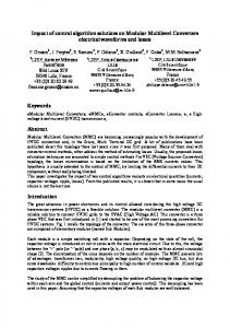
2. Architecture of modular compactor Fig. 1 shows a simple example design with 21 scan chains driven by a Decompressor/Generator and connected to a modular compactor. The Decompressor/Generator is a hybrid design capable of generating pseudorandom patterns in BIST mode and decompressing 2 1 0 1
2
3
4
5
6
7
8
9
10
19
20
29
0
6 5
Table. I. Assignment of scan chains to circular registers for example design from Fig. 1. Leading Cell 0 10 20 30 40 50 60 70 80 90 100
Reg 3 0 1 2 0 1 2 0 1 2 0 1
Reg 7 0 3 6 2 5 1 4 0 3 6 2
Reg 11 0 10 9 8 7 6 5 4 3 2 1
Cell 110 120 130 140 150 160 170 180 190 200
Reg 3 2 0 1 2 0 1 2 0 1 2
Reg 7 5 1 4 0 3 6 2 5 1 4
Reg 11 0 10 9 8 7 6 5 4 3 2
3. Modular arithmetic
4 30
39
3 2
40
49
50
59
1 0
. . .
D e c c o m p r e s s o r / G e n e r a t o r
Fig. 1. Example design with modular compactor
deterministic patterns in test compression mode. An example of such circuit is presented in [16]. In this example, each scan chain is exactly 10 scan cells long. The scan cells are numbered from 0 to 209. The compactor has three circular registers of relatively prime length (3, 7, 11). Each scan chain connects to all registers by an injector XOR network attached to a flip-flop with a number computed by taking the number of the leading cell, i.e., the cell driven by the Decompressor/Generator, modulo the register size. Scan chains with leading scan cell 0, 10, 20, 30, 40, 50, …, 190, and 200 connect to bits (0,0,0), (1,3,10), (2,6,9), (0,2,8), (1,5,7), (2,1,6), …, (1,1,3), and (2,4,2), respectively. Table I provides a complete list of assignments of scan chains to register flip-flops. A simple de-multiplexing circuitry can provide a flexible low area overhead mechanism to read the compacted responses every cycle, once every couple of cycles, every pattern, once every couple of patterns, or even once for hundreds or thousands of patterns in BIST applications. Throughout this paper we assume that one signature is computed for every scan pattern.
10 9 :
190
199
200
209
: 3 2 1 0
Proceedings of the 24th IEEE VLSI Test Symposium (VTS’06) 0-7695-2514-8/06 $20.00 © 2006
IEEE
In general, a modular compactor can have m circular registers of relatively prime length r0 , r1, r2,…, rm-1. The compactor range R is a product of the register lengths R =
m −1
∏ r . The flip-flops within a register i are i
i =0
labeled as 0, 1, 2, …, ri -1. The scan cells are numbered from 0, 1, 2, ..., to N-1. Without loss of generality, let’s assume that there are J scan chains, and all of them, with a possible exception of one, have equal length L. Every scan chain connects to all registers. A scan chain j with a leading cell number jL connects to flip-flop number jL mod ri
of register ri, for j = 0, 1, 2, …, J-1 and i = 0, 1, …, m-1. To simplify the analysis we will work with a single scan chain model in which the scan chain connects to bit 0 of each register. The model is equivalent to the multiple scan chain architecture shown in Fig. 1 in that an error in any scan cell with number i in both schemes results in the same signature. Let c represent a position of an error in the scan chain that feeds the compactor, then its corresponding position si of the error in the signature is defined as a remainder of modulo ri operation, si = c mod ri , where ri is the register size. We use modular arithmetic as the formal tool to study the properties of modular compactors. In particular, we use the Chinese Remainder Theorem [17] to prove that if content of a scan chain is unloaded into the compactor, every scan cell error produces a different signature. Theorem 1 restates that in a form applicable to this paper. Theorem 1: Let c be a scan cell number and (s0, s1, s2, … sm-1) its corresponding signature defined as a set of remainders si = c mod ri, 0 ≤ si < ri, for 0 ≤ i < m. Then, every two different scan cells c and d, 0 ≤ c < R, 0 ≤ d < R, c ≠ d , generate different signatures. The Chinese remaindering [17] is directly applicable to find the erroneous scan cell from the set of recorded remainders as stated in Theorem 2. Theorem 2: Let qi be the product of all the rj`s except ri,
⎞ ⎛ qi = ⎜⎜ ∏ rj ⎟⎟ / ri . Let also zi be an inverse qi-1mod ri , ⎝ j =0 ⎠
25 = 5, 1,019,155 mod 27 = 13, 1,019,155 mod 29 = 8, and 1,019,155 mod 31 = 30.
4. Analysis of error aliasing The analysis of aliasing probability presented here uses the methodology introduced in [5]. It builds on a stationary independent error model where an error occurs independently at each position in the test-response sequence with error probability pe. First, we determine the number of states reachable from the initial all 0 state. Theorem 3: The number of reachable states in a modular compactor with m registers of relatively prime lengths r0 , r1, r2, …, rm-1 is m −1
2∑0
ri − m +1
. Proof: Every bit of the first register can be set or reset independently of other bits. The register therefore can r0 r 0 −1 , are the reach all of its 2 states. Half of them, 2 result of an odd number of error injections and the other half corresponds to an even number of errors. Given that every scan chain connects to all registers, the states that involve odd number of errors on some registers and even number on others are not reachable. The relatively prime length of the registers makes it possible to achieve any combination of odd injections and even injections. Hence, r −1 r −1
r
the total number of reachable states is 2 0 2 1 ...2 m−1 r −1 r −1
r
+ 2 0 2 1 ...2 m−1
r + r1 + ... + rm−1 − m +1
−1
or 2 0
−1
.
m −1
⎛ m −1 ⎞ c = ⎜ ∑ qi zi si ⎟ mod R . ⎝ i =0 ⎠ Example 1: Let’s consider a compactor with five registers of size 23, 25, 27, 29, 31 that records remainders: 2, 5, 13, 8, 30. The compactor’s range is 13,956,975. The corresponding qi ’s are 606825, 558279, 51625, 481275, 450225, and the inverses, zi ’s are 13, 19, 19, 16, and 13. The increase of distance by 606825*13, increments remainder s1 by 1 modulo 23, (606825*13) mod 23 = 1, while preserving all other remainders. Similarly, (558279*19) mod 25 = 1, (51625*19) mod 27 = 1, (481275*16) mod 29 = 1, and (450225*13) mod 31 = 1. A set of recorded remainders 2, 5, 13, 8, 30 corresponds to an error on scan cell c, c = (606825*13*2 + 558279*19*5 + 51625*19*13 + 481275*16*8+450225*13*30) mod 13,956,975 = 1,019,155. A simple verification shows that indeed the error in scan cell 1,019,155 produces the set of remainders: 1,019,155 mod 23 = 2, 1,019,155 mod
Proceedings of the 24th IEEE VLSI Test Symposium (VTS’06) 0-7695-2514-8/06 $20.00 © 2006
IEEE
10000 16 1000 8,9 100
Aliasing ratio
that is qi zi =1mod ri , and 0 ≤ zi < ri. Then, based on the recorded set of remainders (s0, s1, s2, … sm-1), the scan cell number c that originated the error is determined as
It is possible to demonstrate that the process is irreducible, aperiodic, and doubly stochastic. In a process with these properties, in a steady state, every reachable state is equally likely. The probability of returning to the all 0 state, known also as error aliasing, is determined by Theorem 4.
5,6,7
10
1
0.1
3,4,5,7
1
2
3
4
5
6
7
Step [100]
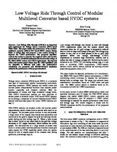
Fig. 2. Aliasing and number of registers
8
9
1.2
Theorem 4: The steady state probability of error aliasing in a modular compactor with m registers of relatively prime length r0 , r1, r2, …, rm-1 , under the stationary independent error model, pe ≠ 0,1, is 2
− ⎛⎜ ⎝
m −1
∑0
ri − m +1 ⎞⎟ ⎠
100 0.001
Aliasing ratio
0.0001 10 0.01 0.1 1
2
3
4
5
6
7
8
9
Step [1000] 0.1
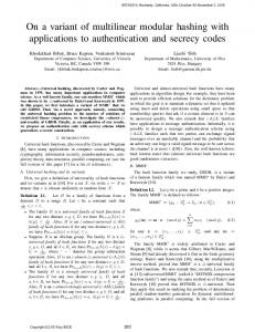
Fig. 3. Aliasing and error probabilities
Fig. 3. shows the process dynamics for one compactor (3,4,5,7) with several values of error probability ranging from 0.0001 to 0.1. The higher the value of pe the faster the process reaches the steady state probability of aliasing. For very low values of pe, the process has much longer transition period and reaches higher maximum value.
5. Analysis of error masking properties A different and very practical way to analyze error masking in compaction schemes is to consider discrete errors of finite multiplicity.
Proceedings of the 24th IEEE VLSI Test Symposium (VTS’06) 0-7695-2514-8/06 $20.00 © 2006
IEEE
1
100000
0.8
10000
0.6
1000
0.4
100
0.2
10
.
In order to understand the dynamics of the process we use a Markov chain simulator that computes states probabilities for every step of test response compaction. Fig. 2 shows charts that correspond to several compactors and the error bit probability of 1%. All compactors have the same number of reachable states 216 and the same steady state probability of aliasing, 2-16. The single-register compactor reaches an intermediate probability of aliasing that is 1000 times bigger than the steady state one. This is entirely consistent with results published in [3,4] that analyze intermediate aliasing in single circular registers. On the other hand, the four-register modular compactor, with similar hardware, reduces intermediate aliasing by two orders of magnitude, to less than 8 times the steady state value.
1
1000000
0
1 1
51
101
151
Fig. 4. Distribution and counts of multiple errors in real fail logs
Fig. 4. shows discrete error statistics from an 8 million gate design fabricated in 110 nm copper technology. The data comes from 3000 failing devices and a total of a quarter of a million failing patterns. It shows that a single error occurred in 77% of the failing patterns, double error in 12%, triple error in 4%, quadruple error in 2%. Ten or less errors explain more than 98% of all failing patterns. Theorem 5: Modular compactor detects all odd multiplicity errors if the test response does not have X states. Proof: In a single register, the total odd number of errors injected into it breaks down into at least one or more flip-flops with an odd number of errors and a set, possibly empty, of flip-flops that have even number of errors. The flip-flop with odd number of errors guarantees detection of the odd scan error. Double error masking does not occur if the length of the scan chain is less or equal to the compactor range. Based on Theorem 1, two errors in different scan cells in the compactor range have different signatures. Therefore, there is at least one register where these two errors affect two different flip-flops. In a general case, where the scan chain length is not limited by the compactor range Theorem 6 determines the probability of double error masking . Theorem 6: The probability of double-error masking in a test response sequence of length N and a compactor of range R , is a (2 N − R(1 + a) ) , where a = ⎢ N ⎥ . ⎢⎣ R ⎥⎦ N (N − 1) Proof: Two errors are masked if they are exactly R positions apart in the scan chain. Number N can be represented as N = aR + (N – aR). The first term, aR, represents a multiple of the compactor range and the second term (N – aR) is the remainder. We need to consider two types of cases: one where both errors are in the cells corresponding to the first term, and another where one error
is in the cells corresponding to the first term and the second error is in the second term. The number of double errors in the first case that mask is a(a – 1)R/2. In the second case, for every error in the remainder, there are a errors that are exactly R scan cells apart, and can mask each other. The number of errors in this case is (N – aR)a. The combined number of masked double errors is a(a1)R/2+(N-aR)a and the total number of double errors equals N(N – 1)/2. The probability of double error masking is a (a − 1) R / 2 + ( N − aR)a , or a (2 N − R(1 + a) ) . N (N − 1) / 2 N (N − 1) Corollary 1: The probability of double error masking in for very large test sequence, N >> R, approaches R–1. Example 2: Fig. 5 shows the probability of double error masking for two compactors: 48-bit four-register compactor (7,11,13,17) and a 49-bit three-register compactor (13,17, 19) as a function of the number of scan cells in hundreds. In addition, the charts include the corresponding asymptotic values, R–1. Although the compactors have similar sizes, the first one has four times bigger range (17017 vs. 4199) and double errors with separation of 17017 or less do not experience masking. 0.00025 (13,17,19) 0.0002 0.00015 0.0001 (7,11,13,17) 0.00005
Step [1000] 0
0
10
20
30
40
50
60
70
80
90 100
Fig. 5. Probability of double error masking
According to our experimental data, 2% of all failing test responses have quadruple errors per failing pattern. This is a significant enough percentage of cases with a potentially measurable impact on quality of test and needs to be carefully considered. Let’s define an error sequence as a list of scan cell numbers that produce errors. In a tworegister compactor (r1, r2), an error sequence {0, r1, r2, r1+r2} results in masking on both registers. Lemma 1 shows that it is the shortest quadruple error masking sequence.
Proceedings of the 24th IEEE VLSI Test Symposium (VTS’06) 0-7695-2514-8/06 $20.00 © 2006
IEEE
Lemma 1: In a two-register compactor (r1, r2), the shortest quadruple error masking sequence is {0, r1, r2, r1 + r2}. Proof: Clearly, error sequence {0, r1, r2, r1 + r2}, produces quadruple error masking. These failing response compacts to the following bits on the first register: 0, 0 (r1mod r1), r2mod r1, and (r1 + r2) mod r1 = r2mod r1. The first two errors mask each other on bit 0, the next two on bit r2 mod r1. Similar arguments apply to the second register. Let’s assume that masking occurs for an error sequence a + r2, where a < r1, that is shorter than r1 + r2 and we will prove that is not possible. Since error a + r2 requires error a, and error 0 requires r2, the only sequence that could mask completely on the second register is {0, a, r2, a + r2}. In order to achieve complete masking, this error sequence must also mask on the first register. Since a is smaller than r1 and r2 is relatively prime with respect to r1, and therefore not a multiple of r1, error 0 can only be masked by an error on cell a + r2. For that to happen, a+r2 has to be a multiple of r1 , a + r2 = k r1, where k is an integer. The remaining two errors on a and r2 must be separated by a multiple of r1 in order to mask on the first register, r2 – a = l r1, where l is an integer. The combined condition is 2a=(k – l)r1 , or 2a=jr1, where j is an integer. Considering that r1 is prime j cannot be 1. If j is 2, a= r1. For any other value of j, a is bigger than r1. This proves that {0, r1, r2, r1+r2} is the shortest sequence that produces quadruple error masking on two prime length registers. Analysis of quadruple error masking in a modular compactor with three or more registers requires understanding of additional conditions. Lemma 2 introduces masking conditions for errors of multiplicity four. Lemma 2: If there are no integers k and l such that (kr3 – lr2)mod r1 = 0, (kr3 + lr2)mod r1 = 0, kr3 + lr2 < r1r2+r3, then the shortest sequence of four errors that can produce masking in a three register modular compactor is: {0, r1r2 , r3, r1r2 + r3}. Proof: The proof follows a very similar method to that used in Lemma 1. Example 3: In compactors (4,7,11), (4,9,13), and (6,13,19) quadruple-error masking occurs in 36, 44, and 96 cycles, instead of the nominal length, r1r2 + r3 corresponding to: 39, 49, and 97 cycles. Considering these masking conditions, design rules for compactors recommend using registers with prime length, excluding number 2. With properly designed compactors the minimum length of a four-error masking sequence is
⎛ ⎞ ⎟ , where A and B are disjoint and r r + ∏ ∏ i j ⎜ i∈A ⎟ j∈B ⎝ ⎠
min ⎜
every register is either in A or B.
Lemma 3: For very large length of scan chain N >> R m −1
quadruple error masking approaches
⎛ 3ri − 2 ⎞ ⎟⎟ . 3 ⎝ ri ⎠
∏ ⎜⎜ 0
Proof: On a single register of length ri, quadruple error masking occurs if either all four errors map to the same flip-flop or to two flip-flops, each receiving two errors. In the first case there are ri masking combinations. In the ⎛r ⎞ second case we have ⎜ i ⎟ combinations of pairs of flip⎜ ⎟ ⎝2⎠ flops. Within each combination of two flip-flops there are 6 different ways to assign pairs of errors: {(1,2),(3,4)}, {(1,3),(2,4)}, {(1,4),(2,3)}, {(2,3),(1,4)}, {(2,4),(1,3)}, {(3,4),(1,2)}. The probability of masking on a single reg-
⎛ ri ⎞ ⎜⎜ ⎟⎟6 + ri 3r − 2 ⎝ 2⎠ , which gives i 3 . ister is 4 ri ri
6. Detection of burst errors In this section, we analyze the ability of modular compactors to detect burst errors. As illustrated by the real fail logs in the previous section, the number of scan cell errors per failing pattern is typically very small. Very often they originate from the same defect location, propagate through one or two cones of logic to scan cells, and exhibit clustering effects well modeled by burst errors. In a test response with a burst error, all erroneous bits cluster within a limited number of consecutive bits. Burst errors begin and end with an error bit. The interleaving bits can be correct or incorrect. The length of the sequence from the first error to the last error defines the error span. Here we consider only one burst error per signature readout, which, in most cases, is a test response to single scan pattern. In this section, we assume that there are no X states in test responses. The main question that needs to be answered is the following. Given a modular compactor with m circular registers of relatively prime length r0 , r1, r2,…, rm-1, what is the maximum span of a burst error that can be detected? The following theorem provides the answer. Theorem 7: The largest span of a burst error guaranteed to be detected in a modular compactor with m circular registers of relatively prime length r0 , r1, r2,…, rm-1, is m −1 ∑0 ri − m + 1 .
Proof: Without loss of generality, we can assume that the end error is located on scan cell 0. Indeed, any error pattern is detected on a modular compactor if and only if a shifted version of the pattern is detected. In a modular compactor, any shifted version of an error results in the
Proceedings of the 24th IEEE VLSI Test Symposium (VTS’06) 0-7695-2514-8/06 $20.00 © 2006
IEEE
same number of error bits on a given circular register as the original burst error. The shifted burst error rotates by the size of the shift. Every bit of a modular compactor performs an XOR operation on a set of variables corresponding to contents of scan cells. Since scan cell 0 has the end error its corresponding variable c0 =1. This also implies that, if there were no other errors, bit zero of every register would have a value 1. The problem of finding the shortest self-masking burst sequence is defined as a system of simultaneous linear equations expressed in a matrix form: Ac = b, , where A is a matrix of coefficients, with ai , j = 1, iff bit i of the compactor depends on variable j, vector c represents error variables associated with scan cells from 1 to ∑ 0m −1 ri ( c0 = 1), and vector b represents the masking conditions on the bits of the compactor. Since the elements of b corresponding to 0 bits have value 1, while every other bit has a 0, this is a nonhomogeneous system of linear equations. Reduced echelon matrices computed for these systems reveal a couple of properties. There are only ∑ 0m −1 ri − m + 1 rows, and m – 1 redundant equations. For every register with exception of one, there is one redundant equation. Because every error is injected to each register, the combined error parity on every register should be the same. There are no free variables within the first ∑ 0m −1 ri − m + 1 columns. It means that this is a unique solution. Once we add the error bit corresponding to cell 0, the minimum span of the selfmasking burst error sequence is ∑ 0m −1 ri − m + 2 . Hence, the longest burst error guaranteed to be detected is m −1 ∑0 ri − m + 1 . Example: Consider a three-register modular compactor (3, 7, 11). The shortest burst error that results in complete masking is a sequence 10111110100101111101 of length 20. This sequence produces an even number of errors on every bit of the compactor. The respective counts of injected errors on the bits listed from 0 to ri − 1 are as follows. On register 0, 1, and 2 it is {4, 4, 6}, {2, 2, 2, 2, 2, 2, 2}, and {2, 0, 2, 2, 2, 2, 2, 0, 2, 0, 0}. Indeed, there are 14 errors in the sequence, and every register accumulates all 14 of them. This compactor detects any burst error of length 19 or less. Table II shows several configurations of modular compactors with three, four, and five circular registers. The range indicates the maximum number of scan cells of a design, that the compactors are most suitable to handle. The “Max Burst” column shows the maximum span error with guaranteed detection. A three-register compactor (37, 41, 43) with a total of 121 bits guarantees no masking for any burst error with a span of 119 or less. The biggest compactor in the table is a five-register, 331-bit compac-
tor capable of compacting 12,000 scan patterns in a 100,000 scan cell design and guaranteeing the detection of any burst error of span 327 or less. Table. II. Examples of compactors, their ranges and detectable burst errors R 1 5 11 17 23 37 41 47 59 11 17 23 31 41 47 13 23 37 47 59
R 2 7 13 19 29 41 43 53 61 13 19 29 37 43 53 17 29 41 53 61
R 3 11 17 23 31 43 47 59 67 17 23 31 41 47 59 19 31 43 59 67
R 4
19 29 37 43 53 61 23 37 47 61 71
R 5
Range 385 2,431 7,429 20,677 65,231 82,861 146,969 241,133 46,189 215,441 765,049 2,022,161 4,391,633 8,965,109 2,800,733 31,367,009 162,490,421 600,662,303 1,249,792,339
29 41 53 67 73
Sum 23 41 59 83 121 131 159 187 60 88 120 152 184 220 101 161 221 287 331
Max Burst 21 39 57 81 119 129 157 185 57 85 117 149 181 217 97 157 217 283 327
To study the masking probabilities of multiple errors in modular compactors we have developed two approaches. The first one assumes independence of operation of registers which is equivalent to assuming that the scan chains are much longer than the compactor range. This assumption simplifies the analysis while giving an upper bound for the actual masking probability. The second approach uses Monte Carlo simulation. In order to determine the masking probability of multiple errors in presence of multiple X sates, we introduce two graphs. An X-graph represents the accumulation of X values in a single register of the compactor. An E-graph models the interaction of errors with the X values. 0
1 (r-1)/r 1/r
2 (r-1)/r 1/r
(r-2)/r 2/r
3 (r-1)/r 1/r
(r-2)/r 2/r
(r-3)/r 3/r
4 (r-1)/r
(r-2)/r
(r-3)/r
(r-4)/r
1/r
2/r
3/r
4/r
1
2
3
4
5
7. Handling of unknown states Modular compactors have fanout-free feedback. An X value injected into a circular register rotates without multiplying itself. By comparison, in a MISR, a single X value reaches all flip-flops in just a couple of cycles rendering the signature useless. Modular compactors have two very important properties related to X masking. Property 1: If the number of scan cells is within the compactor’s range, N < R+1, an X value in a single scan cell does not mask observability of any other scan cell. This property is a derivative of Theorem 1. With the total scan chain size within the compactor range, N < R+1, every scan cell maps to a different set of flip-flops on the compactor. Therefore, there is at least one register where the error and the X value map to different flip-flops guaranteeing detection of the error. Property 2: If the compacted response contains z unknown values and its length is much larger than the period of the compactor, N >> R, the probability of X masking
∏ (1 − (1 − r ) ). m −1
of a single scan cells is
−1 z
i
0
Proceedings of the 24th IEEE VLSI Test Symposium (VTS’06) 0-7695-2514-8/06 $20.00 © 2006
IEEE
5
Fig. 6. X-graph modeling accumulation of X values
Fig. 6 shows an example of an X-graph modeling the accumulation of X values on one r-bit register of the compactor. An X-graph like this is constructed for every register of the compactor. The rows correspond to the number of injected X values, while the columns correspond to the effective number of X values that remain in the register. The graph can have at most r columns regardless of the number of injected X values. The edges of the graph correspond to the possible state changes and the labels indicate the transition probabilities. Initially, the top node has probability 1. After injecting a single X value the system moves to a single effective X value. From this state, another injection of an X value causes a transition to a state with two effective X values with probability (r-1)/r, when the second injection does not coincide with the location of the first X. The graph can also remain in a state with a single X value with probability of 1/r. The probabilities of different distributions of X values are computed row by row. The last row, in this example, shows the probability of 1, 2, 3, 4, and 5 X values after random injection 5 X values. The sum of probabilities in every row adds up to
1. In general, for a given size of the register r j and the total number of X values U, this graph computes the distribution of probabilities p
X
i
two graphs we obtain the masking probability of E errors with U X values as
(r ,U ) , for i = 0, 1, 2, …
⎛ r j −1 X ⎞ ⎜ ∑ p i (r j ,U )p e i (rj , E )⎟ . ∏ ⎜ ⎟ j =0 ⎝ i =0 ⎠ m −1
j
ri − 1 . 0
Number of X states
1.E+00
(r-x)/r
1
x/r
2
3
4
5
6
7
8
9
10 1
1.E-02 1 (r-x)/r x/r
(r-1-x)/r
2
1.E-04
x/r
3
1/r 2 (r-x)/r x/r
(r-1-x)/r x/r
1/r
1.E-06
4
1.E-08
5 6 7 8
(r-2-x)/r x/r
2/r
3 (r-x)/r x/r
(r-1-x)/r x/r
1/r
(r-2-x)/r x/r
2/r
1.E-10
(r-3-x)/r
errors
x/r 3/r
1.E-12
4 0
1
2
3
4
Fig. 7. E-graph modeling error masking
Once the distribution of X value probabilities is determined by the X-graph, the error masking can be computed using an E-graph shown in Fig. 7. In this graph, we assume that there are effectively x bits with X values in the register. The process is invoked for each node in the bottom row of the previous graph to determine the probability of error masking for 1, 2, 3, 4, and 5 X values, and the probability of error masking is computed. The sum of these probabilities determines error masking for the whole register. The rows relate to the number of injected errors, and the columns correspond to the actual number of errors e outside of the bits with X states. The left-most node in each row corresponds to error masking. In general, if a register is in a state with x bits with X value and e bits in error (x,e), upon injection of a single error the system can move to one of three states: a) state (x,e-1) with probability e/r when the new error hits one of the position already in error causing error cancellation, b) state (x,e+1) with probability (r-x-e)/r when the new error hits a bit with no error and no X value, and c) the same state (x,e) with probability x/r when the new error hits one of the bits with X value. The total number of compactor bits with X value and error value cannot exceed the total number of flipflops in the register. This example illustrates the process of injecting four errors into an r-bit register that has x bits with unknown (X) values. In general, for a given number of bits, i, with X values in the register of size r j and the total number of errors E, this graph computes the probability of error masking p
e
i
(r , E ). j
By combining these
Proceedings of the 24th IEEE VLSI Test Symposium (VTS’06) 0-7695-2514-8/06 $20.00 © 2006
IEEE
1.E-14 1.E-16
Fig. 8. Probability of X masking of errors
Fig.8. presents the probability of error X-masking for errors ranging in multiplicity from 1 to 8 and the number of X values ranging from 1 to 10 in a five-register (13,17,19,23,29) 101-bit modular compactor. The chart contains the graph-based calculations superposed with Monte Carlo experiments. For every error multiplicity Monte Carlo experiments are performed for scan chains significantly longer that the compactor range (100,000,000 vs. 2,800,733). In all these cases the results obtained by using these two methods are very similar. For double errors, Monte Carlo experiments were also performed for a 100,000 scan cell structure. Since the scan chain length is within the compactor range, the error masking for two and three X states is reduced to less than 10-6. For triple errors, the compactor can tolerate up to 7 X values and maintain the error masking under 10-6. This 101-bit modular compactor can read one signature per scan pattern providing close to 1000 times compaction of volume of test data on a design with 100,000 scan cells (100,000/101). For this configuration the detection of double errors and no X values is guaranteed. Similarly, there is no masking of single errors by a single X value. The E-graph can be used to compute the probability of masking of even errors. Fig. 9 shows masking probability of errors ranging from 4 to 20 for the same five-register (13,17,19,23,29) 101-bit modular compactor.
1.E-09 1.E-11
4
6
8
10
12
14
16
18
20
Number of errors
1.E-13 1.E-15 1.E-17 1.E-19 1.E-21 1.E-23 1.E-25
the combined length of 130 bits and with a large enough range (1,011,839) to accommodate a design with one million scan cells. It is also guaranteed that every double error is detected. The double error cancellation is completely eliminated. In addition, modular compactors tolerate X states. The detection of every single error is guaranteed even in presence of a single X value. In the example given here, and a similar one shown in Fig. 8, the probability of double-error masking with a single X value is still at respectable level of 10-7. The modular compactor, however, requires higher fanout of four on the outputs of the scan chain, while the non-canceling compactor works with a fanout of two. Control 2 1
Fig. 9. Masking probability of even errors
8. Comparison to other time compactors
Proceedings of the 24th IEEE VLSI Test Symposium (VTS’06) 0-7695-2514-8/06 $20.00 © 2006
IEEE
0
1
2
3
4
5
6
7
8
9
10
19
20
29
30
39
40
49
50
59
0
6 5 4 3 2
. . .
This section compares the properties of the modular compactor introduced in this paper to other time compactors known in the literature. A MISR proposed by Wohl, Waicukauski and Williams [6] represents one of the most refined time compactors and that is why we selected it as one of the solutions we compare the modular compactor to. The MISR has a non-canceling compactor that eliminates compactor cancellation of two-bit errors. This is achieved by two structural properties of non-canceling compactors: 1) each scan chain connects to two outputs, 2) every two inputs share exactly one input. In addition, the authors demonstrate that MISR cancellation can be reduced by well-designed non-canceling compactors, but it cannot be fully eliminated. The example given in [6] shows that while a conventional MISR has the two-error MISR cancellation probability of 1.21x10⁻⁴, the improved design with a 128-bit MISR and non-canceling combinational compactor lowers the twoerror MISR cancellation probability to 3.16x10⁻⁷. MISRs, including the one presented in [6], are inherently unable to tolerate X states. Even a single X state entering a MISR corrupts the signature. The ability of the non-canceling compactor to detect burst errors has not been studies, and at this time remains unknown. In comparison, the modular compactor introduced in this paper completely eliminates double error cancellation. More specifically, double error cancellation is eliminated in all three sources of aliasing: combinational compactor cancellation, as well as in what is equivalent to MISR cancellation, and MISR masking. In other words, the detection of a double error is guaranteed in the final signature. To the best of our knowledge, this is the first time that these properties are demonstrated for a time compactor. Let’s consider a modular compactor with four circular registers of relatively prime length (23, 29, 37, 41) with
D e c o m p r e s s o r / G e n e r a t o r
1 0
10 9 :
190
199
200
209
: 3 2 1 0
Fig. 10. Modular compactor with de-multiplexing read out structure
Mitra, Lumetta and Mitzenmacher [12] introduced a design of an X-tolerant signature register based on statistical coding. Here every bit of the signature register works as a parity bit. The output of every scan chain is XOR-ed with a randomly selected subset of bits in the register. A weighted random pattern generator controls the selection on a cycle-by-cycle basis. In an example given in [12] the signature register has 100 flip-flops and best weight is 1/8. In this case, for 50 bits of compacted response per single X value in the un-compacted test response, the masking probability of a defect producing three scan errors is 10-7. In a modular compactor with 101 bits (13, 17, 19, 23, 29), the probability of not detecting three errors with two X values in the un-compacted response is 10-9 (Fig. 8), or two orders of magnitude less. The X-tolerant signature analyzer does not guarantee the detection of two errors, or any multiple errors. It also does not guarantee the detectablity of single errors with a single X value. Modular compactor has also much simpler design. A simple demultiplexing structure shown in Fig. 10 leverages the shift
function to provide read-out. No shadow register is required. While the X-tolerant compactor connects each scan chain to every flip-flop of the 100 flip-flop compactor (even though in any given cycle only 1/8 of the flipflops might be written to) with the modular compactor the scan chains fanout to only five flip-flops. The modular compactor guarantees the detection of any burst error with a span not larger than 97. By comparison the X-tolerant compactor guarantees detection of burst error with a span of 1.
9. Conclusions In this paper, we introduced a new architecture of a time compactor of test responses. The compactor, although quite simple, has three unique properties that make it very attractive for on-chip test compression and Built-In Self-Test applications. 1) It has an excellent ability to detect a wide range of errors corresponding to real defects. They include all errors of odd multiplicity, double, and quadruple errors. The compactor guarantees non-masking of burst errors with a span approaching the size of the compactor. It reduces dramatically the intermediate values of aliasing compared to circular registers studied earlier. 2) The simple feedback structure of the rotating registers prevents the multiplication of X values, which is a common problem in signature registers based on MISRs. The compactor tolerates a small number of X values in test response with negligible masking of errors. 3) The compactor operation naturally lends itself into powerful formal methods of modular arithmetic. A method of error diagnosis uses the Chinese remaindering to provide identification of erroneous scan cell based on set of remainders. Our future research will focus on this topic.
Acknowledgments The authors would like to thank Prof. Jerzy Tyszer for his comments and acknowledge the useful suggestions of the anonymous reviewers, which helped improving the quality of the paper.
References [1] P. H. Bardell, W .H. McAnney, and J. Savir, Built-In Test for VLSI – Pseudorandom Techniques, Chapter 8, John Wiley & Sons, 1987. [2] R. David, “Testing by Feddback Shift Register,” IEEE Trans. Comput., vol. 29, No. 7, pp. 668-673, 1980. [3] A. Ivanov and V. Agarwal, “On a fast method to monitor the behavior of signature registers,” Proc. ITC, pp. 645655, 1987. [4] G. Edirisooriya and J. P. Robinson, “Aliasing properties of circular MISRs,” Journal of Electronic Testing: Theory and Applications“ pp. 151-158, vol. 4, no. 2, May 1993. [5] T. W. Williams, W. Daehn, M. Gruetzner, and C. W. Starke, “Aliasing errors in signature analysis registers,”
Proceedings of the 24th IEEE VLSI Test Symposium (VTS’06) 0-7695-2514-8/06 $20.00 © 2006
IEEE
IEEE Design and Test of Computers, vol. 4, pp. 39-45, April 1987. [6] P.Wohl, J.A. Waicukauski, and T. W. Williams, ”Design of compactors for signature-analyzers in Built-In Self-Test,” Proc. ITC, pp. 54-63, 2001. [7] J. Savir and W.H. McAnney, “Identification of failing tests with cycling registers,” Proc. ITC, pp. 322-328, 1988. [8] T. Damarla, C.E. Stroud, and A. Sathaye, “Multiple error detection and identification via signature analysis,” Journal of Electronic Testing: Theory and Applications, vol. 7, No. 3, pp. 193-207, 1995. [9] J. Ghosh-Dastidar, D. Das, and N.A. Touba, “Fault diagnosis in scan-based BIST using both time and space information,” Proc. ITC, pp. 95-102, 1999. [10] J. Rajski and J. Tyszer, “Diagnosis of scan cells in BIST environment,” IEEE Trans. Comput., vol. 48, No. 7, pp. 724-731, 1999. [11] I. Bayraktaroglu and A. Orailoglu, “The construction of optimal deterministic partitions in scan-based BIST fault diagnosis: Mathematical foundations and cost-effective implementations,” IEEE Trans. Comput., vol. 54, No. 1, pp. 61-75, January 2005. [12] S. Mitra, S. S. Lumetta, and M. Mitzenmacher, ”X-tolerant signature anaysis,“ Proc. ITC, pp. 432-441, 2004. [13] J. Rajski, J. Tyszer, C. Wang, and S. Reddy, “Convolutional compaction of test responses,” Proc. ITC, pp. 745754, 2003. [14] C. Wang, S. M. Readdy, I. Pomeranz, J. Rajski, and J. Tyszer,”On compacting test response data containing unknown values,” Proc. ICCAD, pp. 855-862, 2003. [15] T. Clouqueur, K. Zarrineh, K. K. Saluja, and H. Fujiwara, “Design and analysis of multiple weight linear compactors of responses containing unknown values,” Proc. ITC, 2005. [16] G. Mrugalski, J. Rajski, J. Tyszer, “Ring generators - new devices for embedded test applications,” IEEE Trans. Computer-Aided Design, vol. 23, pp. 1306 -1320, Sept. 2004. [17] A. V. Aho, J. E. Hopcroft and J. D. Ullman, The design and analysis of computer algorithms, Addison-Wesley, 1974.