1
EtherCAT Tutorial, an introduction for real-time hardware communication on Windows Kevin Langloisa , Tom van der Hoevena , David Rodriguez Ciancaa , Tom Verstratena , Tomislav Baceka , Bryan Convensa , Carlos Rodriguez−Guerreroa , Victor Grosua , Dirk Lefebera and Bram Vanderborghta a
Robotics and Multibody Mechanics Research Group (R&MM), Vrije Universiteit Brussel, Pleinlaan 2, 1050 Elsene. The R&MM Research Group is a partner of Flanders Make.
Abstract—Setting up a real-time hardware communication for applications such as precise motion control can be timeconsuming and confusing. Therefore, a tutorial on the deployment of an EtherCAT protocol is introduced. In this article, the authors situate EtherCAT, briefly discuss the origins and working principles, and mention advantages over other widely used protocols. Additionally, the main objectives of the tutorial and the required software to complete it are presented. Online supplements are included with this article, explaining all steps to run a Simulink model in real-time on a Windows machine within a few hours. Index Terms—EtherCAT, TwinCAT, Robotics, Realtime, Hardware communication.
I. I NTRODUCTION Particular application domains in the field of robotics and industrial automation, require precise motion control capabilities. To achieve this, real-time control systems are key to develop highly dynamic and intelligent robotic systems such as prosthetic devices [1], [2], exoskeletons [3], legged robots [4], humanoids [5], etc. In these high-end motion control applications, there is a need for very fast low-level control loops with data rates in the region of 250 microseconds to 1 millisecond [6]. Furthermore, these systems require accurate time synchronization and high data throughput to which Real-Time Ethernet (RTE) protocols have recently emerged as the leading solution in industry. EtherCAT (Ethernet for Control Automation Technology) is a widely used RTE protocol, which has shown excellent performances at a relatively low cost [7], [8], [9]. To conclude, the simplicity with which it can be deployed and run a Simulink model in real-time, makes EtherCAT a practical solution for robotic prototyping. This article serves as an introduction to a detailed tutorial on how to deploy an EtherCAT master running a Simulink model in real-time on a Windows machine. In the following section, the general working principles and the origins of EtherCAT are summarized. This is in order to situate EtherCAT in the vast family of RTE protocols. Following, the advantages of the protocol relative to other RTE systems and CAN are presented. And to conclude, a summary of the objectives covered in the tutorial are explained, and the required software is listed. In the Kevin Langlois is corresponding author. E-mail:
[email protected]
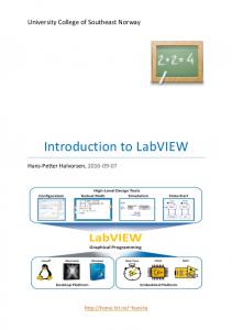
ideal case, the reader should be able to have a simple test-setup running in a matter of hours and with limited hardware costs. The fully detailed step-by-step tutorial can be obtained from the online appendix of this paper. Additionally, the tutorial contains successful implementations on several systems, such as the Cyberlegs Beta-prosthesis (figure 1). II. E THER CAT IN LAYMAN ’ S TERMS In this section the functionality of the EtherCAT protocol is presented. To begin with, the general concepts and origins of industrial communication are briefly recalled, after which, the general working principles that apply specifically to EtherCAT will be mentioned. All of this will be discussed with a certain level of abstraction, as the goal of this tutorial is only to give the reader a basic understanding of the system in order to successfully deploy the protocol. Specific resources are conveyed to the reader interested to delve deeper into the field. A. EtherCAT origins Technologies such as programmable microcontrollers and digital signal processors allowed for the replacement of purely analog control loops with digital controllers such as PLCs. This led to the core of industrial networking, termed fieldbus protocols. Many fieldbusses were developed in parallel, and essentially, every company designed their own protocols, which naturally led to confusion for consumers and developers [11]. As a reaction to this, the Fieldbus War; a web of company politics and marketing interests which in 2000, led to the establishment of an international fieldbus standardization, the IEC 61158 [12], [13], [14], [15]. In the mean time, Ethernet protocols were already well established in the office world. The increased data rates of newer Ethernet standards (for example 802.3u Fast Ethernet) made it easier to create real-time Ethernet protocols, as the transmission and retransmission times are significantly shorter. While primarly Fieldbus systems such as Profibus, SERCOS, CAN and many others have allowed for distributed industrial automation systems, performances of these protocols were considered as too limited when compared to the available performances (mainly in terms of data throughput) of non realtime networks such as Ethernet [16].
2
The variance of the response time of a signal is often referred to as jitter. And low jitter is required due to the fact that variance in time has a negative effect on control loops (the derivative and integral portions of a control loop are affected by time variation). Secondly, the precise clock synchronization of the network. Real clocks drift and will differ in time over long periods. As pointed out in [20], unsynchronized networks usually suffer from non-negligible jitters. In conclusion, a family of RTE protocols has in recent years evolved into a large number of solutions and standards. Two of the most prominent representatives of this group are EtherCAT and Profinet where the former is believed to offer the best performance in terms of communication efficiency and short cycle times [8]. B. Working principle
Figure 1. The CYBERLEGs (CYBERnetic LowEr-Limb CoGnitive OrthoprosthesiS) Beta-prosthesis, which actuates two degrees of freedom (knee and ankle) is controlled via an EtherCAT protocol. The prosthesis integrates series elastic actuators, controlled by custom made electronics boards. [10]
In addition, Ethernet bandwidth enables bus cycle times in the microseconds range instead of the ms range which, together with the superior performance of modern PC-based control systems, allows one to close the control loops over the fieldbus that previously had to be closed locally in the peripheral systems [17]. And finally, the large amount of research that has gone into developing Ethernet as a standard, as well as the cheap and readily available hardware, and the Internet of Things (IoT) [18] with which it becomes possible to connect almost anything with everything, anywhere, illustrates the wish to develop RTE communication protocols. Nonetheless, many challenges presented themselves as the requirements between those two domains - office world and industry - are very different, as discussed in [11], [19]. The two main differences in requirements are related to communication time determinism and precise clock synchronization. Firstly, time determinism, is the requirement for the transmission times of data packets to be known. This means that the latency of a signal must be bounded and have a low variance.
Today, there are over 25 different RTE solutions on the market. They are offered by diverse manufacturers and academic community [19], [9], [16]. These solutions integrate different working principles, such as the method for encapsulation of process data into Ethernet frames, the limitations on network topology, synchronization of the network, implementation costs, etc. First of all, EtherCAT is Industrial Ethernet and utilizes standard frames and the physical layer as defined in the Ethernet standard IEEE 802.3 [21]. Of the fast Ethernet standards, 100BASE-TX is the most common and the one used in EtherCAT networks. By utilizing the full duplex (data transmission in two directions) features of fast Ethernet allows effective data rates of 100 Mbit/s [17]. Furthermore, the EtherCAT protocol employs the master/slave principle to control access to the medium. The master node (typically the control system) sends the Ethernet frames to the slave nodes (such as sensors and actuators), which can extract data from and insert data into these frames. These process data (of all network devices) are carried together in one or more Ethernet frames. This is the so-called summation frame principle as opposed to the individual frame approach in which every frame carries process data for only one device [8]. With EtherCAT the standard Ethernet packet is no longer received, interpreted and copied at every node, instead, slave devices process frames on the fly, reading and inserting data while the frame is passing through the device. This is handled by hardware-integrated EtherCAT Slave Controllers (ESC) in the slaves. The process data in industrial networks are relatively small in quantity (only a few bytes), so that the summation frame method, combined with the “processing-on-the-fly” feature of the EtherCAT slaves, offers good system performance [8], [22]. Moreover, network topology plays an important role when performance of the system is evaluated [22]. Important aspects are not only cycle time or efficiency, but also cabling effort, diagnostic features, redundancy options and plug and play features. EtherCAT networks have no practical limitations regarding the topology, line, star, tree, ring and all those
3
combined with up to 65535 nodes per segment. Then, for synchronization, EtherCAT relies on a clock synchronization mechanism which is known as distributed clock (DC). Basically, clocks of all the DC-enabled slaves in the network are synchronized with a common timing reference under direct control of the master. [7]. Despite being rather simple and straightforward, the DC mechanism enables accurate synchronization (in small-to-medium systems, clock deviations are well below 1 microsecond). III. E THER CAT: A DVANTAGES AND D ISADVANTAGES In this section the advantages of setting up an EtherCAT network over other popular industrial communication protocols are discussed. A. Ethernet based solutions There are more than 25 Ethernet based industrial protocols on the market, but the list of protocols that have a considerable impact on industry is much shorter [23]. They are: - EtherCAT - Powerlink - Ethernet/IP - Modbus/TCP - ProfiNet A multitude of performance evaluations of the remaining systems are reported in literature. The conclusions of these studies are that EtherCAT is an overall highly performing realtime protocol, when compared to the aforementioned protocols [24] [25] [8]. ProfiNet has advantages over EtherCAT in specific conditions, such as efficiency in asynchronous communication [26]. Ethernet/IP neither Modbus/TCP are deterministic and by consequence, are not suited for hardreal-time control. Major advantages of EtherCAT over the ProfiNet and Powerlink are the costs of implementation and the commercial diffusion of the technology [27]. Studies also predict the future pervasiveness of EtherCAT in the industrial automation and robotics fields [23]. This suggests EtherCAT to be the leading communication protocol for these applications. A major other communication protocol which is not part of Ethernet based systems are Serial protocols, of which CAN is widely used in the robotics field. B. Controller Area Network (CAN) Controller Area Network (CAN) still is an adequate choice for low-cost industrial embedded networking. However, Ethernet-based protocols are now able to overcome the shortcomings of CAN, such as limited baud rate and limited network length (1Mb/s at 120 feet). Although the very lowcost implementation as well as the low resource requirements of CAN protocols still make it an adequate choice in certain applications (such as automotive industry, small embedded solutions, aerospace), the overall advantages of EtherCAT over CAN are:
-
Data throughput (currently 100 times higher) Unlimited network length Increased system performances Use of established hardware components IV. E THER CAT DEPLOYMENT
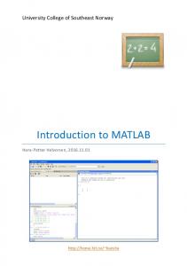
An EtherCAT master runs the EtherCAT network and communicates with all slaves. This master needs to be implemented on a real time operating system. Several solutions have been developed, the one demonstrated in this tutorial is TwinCAT (The Windows Control and Automation Technology). Beckhoff provides the TwinCAT program, whose essential functionality is to reserve a number of physical cores on your personal Windows computer, and run the EtherCAT network from these cores. Windows OS does not run on these cores anymore and only operates on the cores specified by the user. As an example, in this tutorial a quad-core laptop was used where two cores are reserved for the EtherCAT protocol and two cores are used for running Windows. The driver running on the EtherCAT reserved cores is a compiled version of a program that can either be written in PLC language or C/C++ code. Beckhoff provides functionality to run compiled Simulink models (in C++) as drivers in the kernel space. Below, a list is presented with the required software to successfully turn a windows computer into a real-time target running an EtherCAT network. - Microsoft Visual Studio 2010 or higher. Required if programming is directly done in C++, otherwise the shell provided with TwinCAT can be used. - Matlab 2011 (or newer) including Matlab Coder. - TwinCAT 3.1 (Free for non-commercial use). - Beckhoff TE1400 module (Free for simulink models with 5 inputs, 5 outputs and 100 blocks. Larger models require a license). - Microsoft Windows Driver Kit 7 (Free) or higher. The tutorial guides the reader through the implementation of a real-time control loop developed in Simulink and compatible with widely used hardware components (Maxon drivers and motors). The reader is directed through the installation and configuration of all the necessary software on a Windows machine. Debugging tools for TwinCAT and Simulink, as well as instructions on the activation of Beckhoff licenses are included. Additionally, experimental implementations are shown, such as the active prosthesis depicted in figure 1, a frameless brushless motor, depicted in figure 2, and more. V. C ONCLUSION In this article the main outline of a broader hands-on tutorial on the EtherCAT communication protocol for real-time hardware communication in robotics and automation applications is presented. This includes an introduction to fieldbus systems, and a general description of the EtherCAT features. Literature concerning the assessment of the protocol’s performances were conveyed to the reader and the advantages of the protocol were
4
Figure 2. A Kollmorgen RBE type 12 pole frameless motor as used in the test setup. The sensors in the motor include hall sensors for the commutation of the motor and an optical incremental encoder for the position of the motor. A small ring is clamped to the main axle to be able to turn the motor axle manually.
discussed. Conclusively, the technical features of EtherCAT make it an outstanding communication protocol for applications requiring precise motion control, while keeping the implementation cost to a minimum. Additionally, it provides compatibility with common hardware and software. With the appended tutorial the reader should be able to deploy a reliable real-time communication system and run a Simulink control loop in a matter of hours. ACKNOWLEDGMENT This work was supported in part by the ERC-grant ”SPEAR” (no.337596) and the Strategic Basic Research project ”Yves” of Flanders Make. R EFERENCES [1] L. Flynn, J. Geeroms, R. Jimenez-Fabian, B. Vanderborght, N. Vitiello, and D. Lefeber, “Ankle–knee prosthesis with active ankle and energy transfer: Development of the cyberlegs alpha-prosthesis,” Robotics and Autonomous Systems, vol. 73, pp. 4–15, 2015. [2] P. Cherelle, V. Grosu, A. Matthys, B. Vanderborght, and D. Lefeber, “Design and Validation of the Ankle Mimicking Prosthetic (AMP-) Foot 2.0,” IEEE Transactions on Neural Systems and Rehabilitation Engineering, vol. 22, pp. 138–148, Jan. 2014.
[3] S. Wang, L. Wang, C. Meijneke, E. Van Asseldonk, T. Hoellinger, G. Cheron, Y. Ivanenko, V. La Scaleia, F. Sylos-Labini, M. Molinari, et al., “Design and control of the mindwalker exoskeleton,” IEEE transactions on neural systems and rehabilitation engineering, vol. 23, no. 2, pp. 277–286, 2015. [4] C. Semini, V. Barasuol, J. Goldsmith, M. Frigerio, M. Focchi, Y. Gao, and D. G. Caldwell, “Design of the Hydraulically Actuated, TorqueControlled Quadruped Robot HyQ2max,” IEEE/ASME Transactions on Mechatronics, vol. 22, pp. 635–646, Apr. 2017. [5] F. Negrello, A. Settimi, D. Caporale, G. Lentini, M.Poggiani, D. Kanoulas, L. Muratore, E. Luberto, G. Santaera, L. Ciarleglio, L. Pallottino, D. Caldwell, N. Tsagarakis, A. Bicchi, M. Garabini, and M. Catalano, “Walk-Man Humanoid Robot: Field experiments in a postearthquake scenario,” Robotics and Automation Magazine, 2017. [6] P. Neumann, “Communication in industrial automation—What is going on?,” Control Engineering Practice, vol. 15, pp. 1332–1347, Nov. 2007. [7] G. Cena, I. C. Bertolotti, S. Scanzio, A. Valenzano, and C. Zunino, “Evaluation of EtherCAT Distributed Clock Performance,” IEEE Transactions on Industrial Informatics, vol. 8, pp. 20–29, Feb. 2012. [8] G. Prytz, “A performance analysis of EtherCAT and PROFINET IRT,” in Emerging Technologies and Factory Automation, 2008. ETFA 2008. IEEE International Conference on, pp. 408–415, IEEE, 2008. [9] J. Jasperneite, M. Schumacher, and K. Weber, “Limits of increasing the performance of industrial ethernet protocols,” in Emerging Technologies and Factory Automation, 2007. ETFA. IEEE Conference on, pp. 17–24, IEEE, 2007. [10] V. Grosu, C. Rodriguez Guerrero, B. Brackx, S. Grosu, B. Vanderborght, and D. Lefeber, “Instrumenting complex exoskeletons for improved human-robot interaction,” Instrumentation & Measurement Magazine, IEEE, vol. 18, no. 5, pp. 5–10, 2015. [11] B. Galloway, G. P. Hancke, and others, “Introduction to industrial control networks.,” IEEE Communications Surveys and Tutorials, vol. 15, no. 2, pp. 860–880, 2013. [12] International Electrotechnical Commission, International Electrotechnical Commission, Technical Committee 65, International Electrotechnical Commission, and Subcommittee 65C, Industrial communication networks: fieldbus specifications. Part 1, Part 1,. 2014. OCLC: 957247601. [13] M. Felser and T. Sauter, “The fieldbus war: history or short break between battles?,” in Factory Communication Systems, 2002. 4th IEEE International Workshop on, pp. 73–80, IEEE, 2002. [14] J.-P. Thomesse, “Fieldbus Technology in Industrial Automation,” Proceedings of the IEEE, vol. 93, pp. 1073–1101, June 2005. [15] J. R. Moyne and D. M. Tilbury, “The Emergence of Industrial Control Networks for Manufacturing Control, Diagnostics, and Safety Data,” Proceedings of the IEEE, vol. 95, pp. 29–47, Jan. 2007. [16] J.-D. Decotignie, “Ethernet-Based Real-Time and Industrial Communications,” Proceedings of the IEEE, vol. 93, pp. 1102–1117, June 2005. [17] M. Rostan, J. E. Stubbs, and D. Dzilno, “EtherCAT enabled advanced control architecture,” in Advanced Semiconductor Manufacturing Conference (ASMC), 2010 IEEE/SEMI, pp. 39–44, IEEE, 2010. [18] F. Xia, L. T. Yang, L. Wang, and A. Vinel, “Internet of Things,” International Journal of Communication Systems, vol. 25, pp. 1101– 1102, Sept. 2012. [19] M. Felser, “Real-Time Ethernet - Industry Prospective,” Proceedings of the IEEE, vol. 93, pp. 1118–1129, June 2005. [20] P. Ferrari, A. Flammini, D. Marioli, A. Taroni, and F. Venturini, “Experimental analysis to estimate jitter in PROFINET IO Class 1 networks,” in Emerging Technologies and Factory Automation, 2006. ETFA’06. IEEE Conference on, pp. 429–432, IEEE, 2006. [21] “IEEE Standard for Ethernet,” IEEE Std 802.3-2015 (Revision of IEEE Std 802.3-2012), pp. 1–4017, Mar. 2016. [22] M. Knezic, B. Dokic, and Z. Ivanovic, “Topology aspects in EtherCAT networks,” in Power Electronics and Motion Control Conference (EPE/PEMC), 2010 14th International, pp. T1–1, IEEE, 2010. [23] W. Voss, The Future of CAN/CAN open and the Industrial Ethernet Challenge. President esd electronics, Inc USA, 2011. [24] X. Wu, L. Xie, and F. Lim, “Network delay analysis of EtherCAT and PROFINET IRT protocols,” in Industrial Electronics Society, IECON 2014-40th Annual Conference of the IEEE, pp. 2597–2603, IEEE, 2014. [25] J. Robert, J.-P. Georges, E. Rondeau, and T. Divoux, “Minimum cycle time analysis of Ethernet-based real-time protocols,” International Journal of Computers, Communications and Control, vol. 7, no. 4, pp. 743– 757, 2012. [26] R. Schlesinger, A. Springer, and T. Sauter, “New approach for improvements and comparison of high performance real-time ethernet networks,” in Emerging Technology and Factory Automation (ETFA), 2014 IEEE, pp. 1–4, IEEE, 2014.
5
[27] D. Orfanus, R. Indergaard, G. Prytz, and T. Wien, “EtherCAT-based platform for distributed control in high-performance industrial applications,” in Emerging Technologies & Factory Automation (ETFA), 2013 IEEE 18th Conference on, pp. 1–8, IEEE, 2013.
EtherCAT Tutorial, an introduction for real-time hardware communication on Windows Kevin Langlois* a , Tom van der Hoevena , David Rodriguez Ciancaa , Tom Verstratena , Tomislav Baceka , Bryan Convensa , Carlos Rodriguez−Guerreroa , Victor Grosua , Dirk Lefebera and Bram Vanderborghta a
*
Robotics and Multibody Mechanics Research Group (R&MM), Vrije Universiteit Brussel, Pleinlaan 2, 1050 Elsene. The R&MM Research Group is a partner of Flanders Make.
Kevin Langlois is corresponding author. E-mail:
[email protected]
1
1
Introduction
Robots are a growing group of devices that can be used for an ever increasing variety of tasks. Typically robotics is a profession where many different areas of expertise are to be combined into a device that for example interacts with a human or works in a factory. Unfortunately, for the majority of robotics researchers excellence in all areas simultaneously is not easy. Often, excellence in mechanical engineering appears to go hand in hand with the slight neglect of practical programming of control architectures. It is typically in a prototype lab, as the example above illustrated, that many mechanically oriented engineers need ’that one control guy in the lab’ to get their mechanical structures to move, let alone be controlled properly. Figuring out the best hardware control strategy, learning to code in a new language and many other practical problems often discourage the mechanically oriented engineer to properly control their own test-setups. Naturally you will have to annoy your fellow researchers with questions on ‘how to move your setup or robot’. If we break the problem of ’moving your setup or robot’ down a little there are three different building blocks that need to be considered. Firstly, on the most mechanical level there are motors that actuate your setup and sensors that measure the state of the motor. These motors naturally need to be regulated with a voltage, and this task is performed by a low-level motor controller. The low-level motor controller generally reads the sensors on the motor axis to determine the current motor state and accepts a position/velocity/torque setpoint from a high level control program to set a desired motor state. The low-level motor controller then moves from the current state to the desired state by applying the required voltage to the motor. Secondly, on the most control oriented level there is the high-level control program. This control strategy could for example be that your motor has to track a certain reference trajectory with the use of a PID controller. Thirdly, there is the communication between the high level control program and the motor controller. This ’hardware communication layer’ can be done in many ways. A widely used high performance solution is to use an EtherCAT network. Such a network can easily run at 1kHz on your own computer to ensure real-time communication between your measurement/actuation setup and your personal computer. Therefore this tutorial will focus on exactly what EtherCAT is, what make up the key components of an EtherCAT network and most importantly: how you can setup your very own network for your measurement setup or your robot. A tutorial is presented on how to get a Simulink measurement model running on a Windows machine with a real-time EtherCAT network. This tutorial includes real-time tracking of a reference trajectory with a motor and reading values realtime from sensors. Throughout the tutorial additional information is presented on the components that make up the EtherCAT network. As you will read in this instructive document, an EtherCAT network consists of a master and several slaves. The tutorial part focuses on the master side of the EtherCAT network, or in other words the
2
software that runs and maintains the communication in the network. The remainder of this document is structured as follows. Section 2 contains an instructive and comprehensive overview of what an EtherCAT network is and what the key components are in such a network. In section 3 the tutorial for a prototyping test setup is presented. All required (mostly free) software is clearly listed and the main installation sequences are illustrated with the essential ’print-screens’. The basic control systems developed in this tutorial are based on Maxon driver boards and controllers, however any EtherCAT slave module or device can also be used to achieve a running setup. Debugging tools in Simulink and TwinCAT are introduced in section 4. Section 5 is dedicated to the licensing of TwinCAT products, allowing the user to integrate more complex models. Additionally, we added some experimental implementations of the EtherCAT protocol in section 6, illustrating possible application domains. Lastly in Appendix A an informative section is presented on the different EtherCAT slaves. Throughout the tutorial, references are made to any available additional online material and examples. As a final note, it should be stated that there is no part in this work which can be considered really ‘novel’. The majority of the work can be constructed by combining various documents and films on the web and the EtherCAT technology exists already for quite some years. The tutorial is merely intended as an introduction to a high performance hardware communication protocol for hard real-time applications and which is compatible with Simulink. In this way we hope to give the reader a shortcut to a functional system with low hardware costs.
3
2
EtherCAT, TwinCAT, master and slaves
This section contains a start to the background information on EtherCAT networks. It is not the intention of this tutorial to explain the detailed working principles of the protocol, but merely give the reader a general understanding of the technology in order to complete this tutorial. For a more detailed explanation, the reader is referred to the Beckhoff Information System website [1]. First, a small section is devoted to what EtherCAT is and what makes up an EtherCAT network. Secondly, a section is devoted to TwinCAT as a master environment to an EtherCAT network.
2.1
What is EtherCAT?
EtherCAT is a way to communicate between a computer and motor drives and all sorts of analog and digital inputs and outputs (IO). The main advantage compared to any other ways to do the same communication like USB, RS232, CAN, etc. is that this type of communication is Industrial Ethernet (and utilizes standard frames and the physical layer as defined in the Ethernet Standard IEEE 802.3 [2]) and can achieve real-time communication. Realtime communication generally means that information (like setpoints for the motor or readings of the sensors) can be sent over the network at a high frequency (1kHz or higher). Today, there are over 25 different Real Time Ethernet (RTE) solutions on the market offered by diverse manufacturers and the academic community [3], [4], [5]. These solutions use different approaches regarding the method for encapsulation of process data into Ethernet frames, which offer different advantages. EtherCAT protocol is based on so-called summation frame principle in which the process data of all network devices are carried together in one or more Ethernet frames, as opposed to the individual frame approach in which every frame carries process data for only one device [6]. Also, with EtherCAT the standard Ethernet packet (containing data) is no longer received, interpreted and copied at every slave, instead, slave devices process frames on the fly, reading and inserting data while the frame is passing through the device. This is handled by hardware-integrated EtherCAT Slave Controllers (ESC) in the slaves. Process data in industrial networks are relatively small in quantity (only a few bytes), so that the summation frame method, combined with the “processingon-the-fly” feature of the EtherCAT slaves, allows to achieve good system performance when compared to other protocols [6], [7].
2.2
Master/Slave Architecture
EtherCAT employs the master/slave principle to control access to the medium, see figure 1. The EtherCAT master (typically the control system) uses a standard Ethernet port and network configuration information stored in the EtherCAT Network Information file (ENI). The ENI is created based on EtherCAT Slave Information files (ESI) which are provided by the vendors for every device. The master node sends the EtherCAT frames to the slave nodes, which can extract 4
data from and insert data into these frames, schematically represented in figure 2. Slave nodes are devices such as EPOS3 motor drives which have the Ethernet ports on it to communicate with an EtherCAT master. An EtherCAT master is a computer device which maintains the data communication between the master and the different slaves.
Figure 1: The EtherCAT network architecture, consisting of a master/slave protocol.
Figure 2: The EtherCAT frame simply replaces the IP frame of a standard Ethernet message. Thus, the Ethernet frame does not need modification, contributing to flexibility for EtherCAT.
5
The EtherCAT frame starts with a standard header which tells the nodes how long the EtherCAT portion of the frame will be. After the header, the frame contains Process Data Objects (PDOs). The PDOs correspond to the number of nodes and contain data for a node. The PDOs are individually addressed, telling the nodes which PDOs to take. This is an important term as we will later see, when our control model’s inputs are linked to the hardware outputs. The final portion of the frame is the working counter which ensures the entirety of the frame was received by the node. Network topology plays an important role when performance of the system is evaluated [7]. Important aspects are not only cycle time or efficiency, but also cabling effort, diagnostic features, redundancy options and plug and play features. EtherCAT networks have no practical limitations regarding the topology, line, star, tree, ring and all those combined with up to 65535 nodes per segment. For synchronization, EtherCAT relies on a clock synchronization mechanism which is known as distributed clock (DC). Basically, clocks of all the DC-enabled slaves in the network are synchronized with a common timing reference under direct control of the master. [8]. Despite being rather simple and straightforward, the DC mechanism enables accurate synchronization (in small-to-medium systems, clock deviations are well below 1 microseconds).
2.3
TwinCAT
On the software side, different master environments exist, such as Etherlab, Labview-realtime and SOEM/ebox, but in this tutorial we will use TwinCAT (The Windows Control and Automation Technology). The reason being that it does not require a Linux computer and is generally easy and user-friendly to operate. Basically, TwinCAT allows to to reserve some cores in a personal windows computer, make a link to the kernel space of the computer and turn it into a realtime target that can run and maintain an EtherCAT network. TwinCAT 3 eXtended Automation Engineering Environment (XAE) allows the integration of additional programming languages or tools, such as MATLAB and Simulink, see figure 3. Users can design their control algorithms in MATLAB and Simulink, and use Simulink Coder to generate TwinCAT modules. The integration of MATLAB and Simulink into TwinCAT 3 facilitates a connection to the scientific field by integrating the TwinCAT real-time execution of tasks and modules into Microsoft Visual Studio. In conclusion, we know that TwinCAT is a program to implement a realtime target that runs an EtherCAT network between a master, such as a Windows machine, and the slaves, such as motor drives and IO. In the next section, we present the implementation of a Simulink model on this realtime target created in TwinCAT.
6
Figure 3: TwinCAT 3 eXtended Automation Engineering Environment (XAE) allows the integration of MATLAB and Simulink .
7
3
Tutorial
In this section the implementation of a Simulink model on the realtime target created with TwinCAT is detailed. To start, in section 3.1, the required software to complete this tutorial is listed. This is assuming a computer with only blank Windows 7 or 10 running on it. Secondly, in section 3.2, the software installation sequence is explained. Thirdly, section 3.3 introduces a simple Simulink model along with the instructions on how to compile the model into a module that can be run on the TwinCAT target. Fourthly, in section 3.4, the realtime TwinCAT target is set up, the compiled Simulink model is imported and the inputs and outputs of the (compiled) Simulink model are connected to the variables of the EtherCAT network slaves. Lastly, in section 3.5, an instruction is presented on how to run the compiled Simulink model on the TwinCAT target.
3.1
List of required and provided software
This is a list of the required software to complete the tutorial. The following programs must already be preloaded on the computer or installed from the various software companies that provide them: - Microsoft Visual Studio professional 2010 or newer. - MATLAB 2015b (including MATLAB Coder, which in some cases is part of the academic license). - The ’general target model’ as included with this tutorial. This can however easily be replaced by any other model. - Microsoft Windows Driver Kit 7 or higher (Installation “Microsoft Windows Driver Kit (WDK)”). Additionally the following software should be downloaded from the Beckhoff site when specified in the tutorial, so not right now. - TwinCAT 3. - Beckhoff TE1400 module.
3.2
Installation and downloading of software
Please follow the instruction sequence for all programs presented in this section carefully, it does matter in which order programs are installed.
8
1. Install Microsoft visual studio 2010 professional - In order to build C++ programs with TwinCAT a version of Visual studio professional 2010 or newer is needed. If the (future) intention is to code directly in C/C++ in TwinCAT install the professional version of Visual Studio. - If you will only use PLC programs or compiled Simulink models, you may use the Visual Studio shell that comes with TwinCAT. 2. Install TwinCAT 3 eXtended Automation Engineering TwinCAT 3 eXtended Automation Engineering Environment (XAE) allows the integration of additional programming languages or tools, such as MATLAB and Simulink. Users can design their control algorithms in MATLAB and Simulink, and use Simulink Coder to generate TwinCAT modules. 1. Navigate to the Beckhoff website to download the TwinCAT 3.1 - eXtended Automation Engineering (XAE) program: https://www.beckhoff.com/english.asp?download/tc3-downloads.htm 2. Select TE1xxxx Engineering. 3. Select TwinCAT 3.1 - eXtended Automation Engineering (XAE). 4. Start the download and follow the instructions. When asked whether you want to integrate TwinCAT into Visual Studio 2010 professional, do it. Don’t use the Visual Studio 2010 shell. 5. TwinCAT 3.1 should now run inside Visual Studio 2010 professional. 3. Install Microsoft Windows Driver Kit 7 (WDK) Implementing TwinCAT3 C++ modules requires parts of the Microsoft “Windows Driver Kit 7 (WDK)”. The steps to install the driver kit can be found on the Beckhoff Information System website [1] and are represented here: 1. Download the “Windows Driver Kit 7.1” from the Microsoft Download Center. http://www.microsoft.com/downloads/en/details.aspx?displaylang= en&FamilyID=36a2630f-5d56-43b5-b996-7633f2ec14ff 2. After download burn a CD from the downloaded ISO image or make use of virtual CD software. 3. Start “KitSetup.exe” from the CD / downloaded ISO image (on Windows7 machines please start installation with “Run As Administrator...”). 4. Select option “Build Environment” - all other components are not required by TwinCAT 3 - and “OK” to proceed. See figure 4.
9
Figure 4: Installation of the Windows Driver Kit 7.1. Select option “Build Environment” - all other components are not required by TwinCAT 3
5. After agreeing to the Microsoft EULA license please select a target folder for the installation. 6. Start installation with selecting “OK”, such as depicted on figure 5.
Figure 5: Installation of the Windows Driver Kit 7.1. Select option ”Build Environment” - all other components are not required by TwinCAT 3
7. Navigate to “Start”-> “Control Panel” -> “System” and select “Advanced system settings” 8. Select tab “Advanced” and click on “Environment Variables...” 10
9. In the lower area for “System variables” select “New..” and add following information: Variable name WINDDK7 Variable value C:\WinDDK\7600.16385.1 The path may differ due to a different version of Windows Driver Kit or a different installation path during installation. See figure 6.
Figure 6: Environment variable ‘WINDDK7’ added.
10. After installation re-login or reboot the machine for establishing the new environment variable settings. Test signing - For the implementation of TwinCAT 3 C++ modules on x64 platforms the driver must be signed with a certificate. 11. Enter the following in the Visual Studio prompt with administrator rights: makecert -r -pe -ss PrivateCertStore -n CN=MyTestSigningCert MyTestSigningCert.cer - This is followed by creation of a self-signed certificate, which is stored in the file “MyTestSigningCert.cer” and in the Windows Certificate Store.
11
- The result can be verified with mmc (Use File->Add/Remove Snap-in->Certificates). See figure 7.
Figure 7: Verify the self-signed certificate was created.
- Configuring the certificate such that it is recognized by TwinCAT XAE on the engineering system. 12. Set the environment variable “TWINCATTESTCERTIFICATE” to “MyTestSigningCert” in the engineering system or edit the post-build step of “Debug—TwinCAT RT (x64)” and “Release—TwinCAT RT (x64)”. The name of the variable is NOT the name of the certificate file, but the CN name (in this case MyTestSigningCert). See figure 8.
Figure 8: Set the environment variable “TWINCATTESTCERTIFICATE” to “MyTestSigningCert”.
13. Activate signing mode, so that Windows can accept the self-signed certificates. Use a command prompt to execute the following: bcdedit /set testsigning yes 14. Restart the target system.
12
- If test signing mode is enabled, this is displayed at the bottom right of the desktop, such as depicted on figure 9. The PC now accepts all signed drivers for execution.
Figure 9: If test signing mode is enabled, this is displayed at the bottom right of the desktop.
15. TwinCAT is now configured to be able to run C++ modules.
4. Install MATLAB - Install a version newer than MATLAB 2011a. The most important thing is that the version of MATLAB includes the MATLAB/Simulink Coder app. 5. Install Beckhoff TE1400 Module The TwinCAT MATLAB/Simulink Target offers System Target Files for the use of the MATLAB/Simulink coder. It enables the generation of TwinCAT 3 runtime modules, which can be instanced and parameterised in the TwinCAT 3 engineering environment. 1. Navigate to the Beckhoff website to install the TE1400 module: https://www.beckhoff.com/english.asp?twincat/te1400.htm. 2. Press the download button and follow all instructions. 3. Start the ‘TE1400-TargetForMatlabSimulink’ Setup. 4. Start MATLAB and execute %TwinCAT3Dir%..\Functions\TE1400- TargetForMatlabSimulink\SetupTwinCatTarget.p such as on figure 10. Do not forget to run MATLAB with administrator privileges.
13
Figure 10: Installation of the TE1400 module
All required software is installed and should be operational
3.3
Simulink model and compilation
In this section we analyse the setup of the Simulink model file that is provided online with this tutorial. We will compile the Simulink model and import it in TwinCAT which is running in Visual Studio. Main model In figure 11 the main Simulink model is depicted. Some text is provided to function as a quick memory-help on how to use the model. In the top section of the model the inputs that have to be read from hardware can be distinguished. The ‘TC Module Input’ blocks can be found in the library browser under ‘beckhoff’. The data type of the input blocks must be configured to match the data type that the real hardware device emits over the EtherCAT network. For example, a motor drive sends the current motor position as an INT16, the input block in Simulink has to be configured to read an INT16. The ‘To file’ block has to be configured for arrays. Also make sure to change the file location to .../general target/temp data. Further reading on this topic can be found in the document http://download.beckhoff.com/download/document/ automation/twincat3/TwinCAT_3_Matlab_Simulink_EN.pdf on page 24. In the middle section the motor trajectory is read from the work space and written to a model output. This ‘TC Module Output’ block can also be found in the model library browser under ’beckhoff’. The trajectory has to be generated with the ’generate model trajectory’ m-file that is supplied with the Simulink model. Do not forget to assign a valid data type for the trajectory output. The bottom section handles the enabling of the motor drive and the starting and
14
stopping of the data saving.
Figure 11: The main Simulink model for this tutorial. The top section are the three inputs read from the hardware (two encoders and one torque sensor), the middle section is where the desired position is sent to the driver’s input, and the lower section enables or disables the logging of the data and the motor driver.
Compiling the model to C++ code In order to run the Simulink model on the real-time target created in TwinCAT, the Simulink model must be build into C++ code and compiled onto the target. In this section the main screens are presented for setting up MATLAB Coder to do the job. In the Simulink model press ’Ctrl+H’ to open the model explorer. The screen in figure 12 will appear. Click on ’Configuration (active)’ in the menu on the left. There are three important items in the list in the middle. These three items are ’Solver’, ’Data Import/export’ and ’Code generation’.
15
The solver has to be set to a fixed step solver because the model runs at a fixed frequency. The stop time does not really matter, the model will continue running after the specified ten seconds. Under ´additional options’ the fixed step time can be set to 0.001 s, which equals a cycle frequency on the EtherCAT network of 1kHz, such as in figure 13. In figure 14, the ‘Data Import/Export’ item is configured (midpane). Saving data to the MATLAB workspace is not possible via this route, but has to be done in a different way that we will see later.
Figure 12: The main screen of the model explorer, with on the left the ‘Configuration (Active)’ pane and in the middle, the ‘Solver’, ‘Data Import/Export’ and ‘Code Generation’ items.
Figure 13: The solver has to be set to a fixed step solver. The stop time does not really matter, the model will continue running after the specified ten seconds. Under ‘additional options’ the fixed step time can be set to 0.001 s.
16
Figure 14: In the ‘Data Import/Export’ block, switch off the ´save to workspace’ boxes.
In figure 15 the target is selected. Click ‘Browse...’ to select Twincat.tlc. Move over to the tab ‘Tc build’, see figure 16. Here, we publish the Simulink TcCOM module. This module is what we will import in TwinCAT to run on the real-time target. In this case we publish both a Realtime(RT) 64 bit (x64) and a Realtime(RT) 32 bit (x86) module such that it can also run on a 32 bit machine if required. This is not mandatory, you can also build the module for your system only.
17
Figure 15: Enlarged screen for code generation where the target can be selected. Browse for the Twincat.tlc file.
18
Figure 16: The screen for publishing the Simulink TcCOM module. If you run a 32 bit computer make sure to publish the generated C++ module for a 32 bit target (x86).
The last two tabs that need to be considered are the ‘Tc External Mode’ and ‘Tc Advanced’ tabs. In the ‘Tc External’ tab, figure 17, we can select whether we want to control the Simulink model running on the real-time target with the Simulink model running in MATLAB. Technically this means that an ADS (Automation Device Specification) protocol is set up between MATLAB and TwinCAT. It is a method for accessing the Bus Coupler information directly from the PC. For the rest of the tutorial we will use this protocol, and thus, check all boxes under the tab ‘Tc External Mode’.
19
Figure 17: The ADS (Automation Device Specification) protocol is set up between MATLAB and TwinCAT. Check all boxes to allow the Simulink model running on the real-time target to be controlled by the Simulink model running on MATLAB.
Lastly, move to the ‘Tc Advanced’ tab, depicted in figure 18. In this tab, we can decide how the generated module should be called. Make sure the task assignment is set to ‘ManualConfig’, the callby is set to ‘CyclicTask’ and step size is set to ‘RequireMatchingTaskCycleTime’. This is because we require the model to be called by a ‘task’ that has the same cycle time as we compiled for the model (1ms).
Figure 18: This is the ‘Tc Advanced’ tab. Here, we can define how to call the real-time generated module. In this case, we require the model to be called by a ’task’ that has the same Cycle time as we compiled for the model (1ms).
The remaining tabs are not considered important at this point. Having completed these steps you can return to the ‘General’ tab and press ‘Generate Code’. MATLAB will now start compiling your model and publish it to a directory where TwinCAT can read it.
20
3.4
Setting up the TwinCAT real-time target and importing and connecting the compiled Simulink model
In order to set up the TwinCAT realtime target, we follow 4 steps: 1. Any EtherCAT slaves, like in our case an EPOS3 motor drive and a Beckhoff module, are connected to the EtherCAT network master. 2. Importing the compiled Simulink model into the TwinCAT environment and setup to run on the real-time target. 3. Connection of the inputs and outputs of the Simulink model to the EtherCAT slaves in the network. 4. The ’ExtendedFileWriter’ module for writing data from the real-time target to the hard drive of the computer is added and connected in TwinCAT. All these steps are explained in this section. TwinCAT real-time target Start up Microsoft Visual Studio. Create a new project (File -> New -> Project). We make a TwinCAT XAE project, and name it ‘simulink realtime target’. We now see the main TwinCAT screen as depicted in figure 19. On the left the project solution tree can be found. Under ’System’ the parameters for the realtime part of the system and the task execution speeds are set. Also, the Simulink model will show up here. Under PLC, we can write programs to be executed by our hardware in PLC language. Under C++ we can write programs to be executed by our hardware in C++ code and under I/O all hardware in our system is listed.
Figure 19: The main screen of a TwinCAT project with on the left, the project solution tree.
21
In the tree, by expanding the ‘SYSTEM’ tab we can create a new task (right click ’tasks’ -> add new item). Name it ‘SimulinkTarget’ and reduce the ’Cycle Ticks’ to 1. This means the task cycle time is set to 1ms. Simulink model import Just like any program written in PLC language or C++ language, the Simulink model will function as the ’high level control program’ that works with the hardware listed under IO. To import the Simulink model, add a new TcCOM object (right click TcCOM Objects -> add new item). Expand TE1400 Module Vendor, like in figure 20, and select ‘general target model’.
Figure 20: To import the real-time generated Simulink model into TwinCAT, a TcCOM object was added. If needed, multiple models can be imported and run simultaneously.
By expanding ‘TcCOM Objects’ and double clicking ‘Object1’, the Simulink block diagram can be found, see figure 21.
22
Figure 21: By expanding ‘TcCOM Objects’ and double clicking ‘Object1’ in the left tree, we can find the Simulink block diagram under the ’Block Diagram’ tab.
Now select the ’context’ tab (double clicking ‘Object1’ in the left tree). In the ’task’ dropdown menu select the ‘SimulinkTarget’ task, see figure 22. This procedure links the model to the task that we created before. In this way, the task is updating every 1ms which means the Simulink model will run at 1kHz.
23
Figure 22: This screen shows how to link the Simulink model to the task that will run one loop of the model, every 1ms.
EtherCAT slaves In the top menu bar, click TwinCAT and select from the drop down menu ’Show Realtime Ethernet Compatible Devices...’ like in figure 23. Under ‘Compatible Devices’ select your Local Area Connection and install, however in your university/lab it may already be done. In this case you can skip this step. TwinCAT only supports intel LAN cards. After installation, your Local Area Connection should show up under ‘Installed and ready to use devices’, like in figure 24.
24
Figure 23: This screen shows the access to the configuration of the Local Area Network card.
Figure 24: Here, the LAN card can be enabled or disabled. If TwinCAT does not recognise your IO (later in this tutorial) or does not go into ’run mode’, reset your LAN card.
Now we can add some hardware to the project. In the tree on the left expand the I/O tab. Right click ‘devices’ and click scan like in figure 25. When all connected 25
hardware is powered and running, this wizard will find it automatically in the network.
Figure 25: This wizard will automatically look for hardware connected in the network.
If devices are recognised we get notified such as in figure 26. If a ‘hardware protocol’ was found, something is wrong. Check first if all the devices are powered on. Another issue can be outdated firmware on the device.
Figure 26: When devices are recognised, you will get this screen.
Proceed to add the hardware to the project and scan the network for boxes. 26
Append the axis to NC axis. Activate free run. In the model tree on the left you will now see the EtherCAT hardware in your network. As depicted in figure 27 in our case, this is an EPOS3 drive, a MIR device to read encoders and a Beckhoff EK1100 module. TwinCAT can only recognise devices if it has their .ESI file. This file contains information about the device functionality and settings. In this case, you need to download the ESI (EtherCAT Slave Information) file for the EPOS3 drive from the Maxon website and copy it to the folder Twincat\3.1\Config\Io\EtherCAT. After doing this, TwinCAT should be able to see your device. Note it is possible that an etherCAT enabled device requires more than a .xml (ESI) file for proper operation. Always ask the device manufacturer if you have all the right files.
Figure 27: Overview screen with on the left all hardware listed in the model solution tree.
Double click the EPOS3. Select the ’slots’ tab like in figure 28. In here, the EPOS3 can be configured in different modes. Each mode has a specific PDO configuration so if you change mode it is likely that links you make to these PDO entries (as explained later in the tutorial) will be lost. A solution can be CST/CSV/CSP mode where you can toggle between any mode you want and the PDO’s contain all entries for current position/velocity/torque and current/velocity/position setpoints. Further reading on the EPOS3 can be found in the application notes of the Maxon website.
27
Figure 28: This is the ‘slots’ tab where the EPOS3 can be configured in different modes.
Put the drive in Continuous Cyclic Position (CSP) mode by selecting whatever is in the left screen (in this case PP/PV mode), pressing the ’x’ button in the middle, selecting the CSP mode in the right screen and pressing the ’