Evaluation of a fast symmetric cryptographic algorithm based on the chaos theory for wireless sensor networks Ismail M ANSOUR∗ , G´erard C HALHOUB† , Bassem BAKHACHE‡ ∗† Clermont
Universit´e / LIMOS CNRS University ∗
[email protected], †
[email protected], ‡
[email protected] ‡ Lebanese
Abstract—Wireless sensor networks are being more and more considered for critical applications where security issues are a priority. Security protocols are based on complicated algorithms that are very time consuming. The limited processing capabilities of sensor nodes make these protocols even more time consuming. Security algorithms based on the theory of chaos have been introduced in order to reduce the complexity of cryptographic operations. A novel chaos based algorithm aiming at enhancing the security robustness has been proposed for wireless sensor networks. On the other hand, a version of the well known AES algorithm has been adopted by various wireless sensor networks standards such as ZigBee, WirelessHART and ISA100.11a, for it is considered as a reliable and robust algorithm. In this paper, we evaluated both algorithms on TelosB motes and prove that the chaos based algorithm is much faster than the AES based algorithm and still achieve merely the same cryptography quality.
Keywords: chaos cryptosystem, AES encryption, wireless sensor network, security. I. I NTRODUCTION Security in wireless sensor networks (WSN) has recently occupied researchers since this technology is being considered for use in critical applications such as in the industrial or the military domains [1], [2], [3]. Most of security protocols are based on symmetric cryptography algorithms which are known to be faster to be executed than asymmetric cryptography algorithms [4], [5]. AES (Advanced Encryption Standard) is an algorithm specified for the encryption of electronic data. It has been adopted by the U.S. government and is the first publicly accessible open cipher approved by the NSA (National Security Agency) for use to protect top secret information [6]. AES is a symmetric-key algorithm, which means that the same key is used for both encrypting and decrypting the data. The counter mode of AES (AES-CTR) is used to ensure confidentiality and is adopted by various wireless networking standards. This algorithm is known for its robustness but also for its complexity and time consumption in WSN. In other hand, Chaos functions have been mainly used to develop mathematical models for non-linear systems. Recently, the chaotic system has gain interests in various fields of scientific research. In fact, important features of chaotic signals,
such as: pseudo-randomness, ergodicity, constant power and sensitivity to initial conditions and parameters of the system, encourage their use in cryptography systems for data security [7], [8], [9], [10]. In [11], authors proposed a novel and fast symmetric algorithm for cryptography that suits better the limited resources of sensor nodes. This novel algorithm is based on the chaotic system and it is proposed to replace AESCTR in WSN. The main contribution of this paper is the evaluation of the performance of the chaos based algorithm that was proposed in [11] for wireless network industrial control in comparison with the AES-CTR algorithm. We implemented both the AES-CTR and the chaos based algorithm on TelosB motes [12]. Results show us that the chaos based algorithm is much faster than the AES-CTR algorithm and at the same time both algorithms give merely similar results in terms of quality of encryption. The paper is organized as follows. In section II we describe the AES-CTR algorithm, in section III we give details about the chaos based algorithm. In section IV we present the implementation results that we obtained before concluding the paper in section V. II. AES-CTR
ALGORITHM
In this section, we present the AES based algorithm and give details about how we implemented its main functions. A. AES algorithm AES supports various key sizes: 128, 192 and 256bits. The number of encryption/decryption rounds depends on the size of the key: for a 128-bit key 10 rounds are used, for a 192-bit key 12 rounds are used, and for a 256-bit key 14 rounds are used. Initially, the plain text is organized into a 4 × 4 array of bytes called state. Each round (except the initial and final round) contains the following functions: (i) AddRoundKey for combining the round key with the state, (ii) SubBytes for replacing every byte with another one according to S-Box, (iii) Shif tRows for shifting each row of the state with a certain offset, and (iv) M ixColumns for combining the four bytes in each column using an invertible linear transformation.
Industrial wireless sensor networks standards such as ZigBee [13], WirlessHART [14] and ISA100.11a [15] use the AES algorithm in counter mode (AES-CTR)[16] for ensuring confidentiality and protecting high priority data. The presented implementation in [17] shows that AES still suffer from high computational time and energy consumption. In the wireless sensor networks domain, the lifetime of nodes, and that of the network in general, is very crucial. The complexity of the network protocols is also to be avoided in order for the nodes to be able to respond in time to any message exchange (keeping in mind the limited capacity of the micro-processor used on the motes). Thus, the execution time and the energy consumption are often behind the choice of encryption algorithms. B. The main functions of the AES-CTR algorithm The AES-CTR algorithm is somehow look like a stream cipher, because the counter is encrypted then applied to data before transmission. We implemented AES-CTR to encrypt messages exchanged between 2 nodes in a WSN. Messages are divided into blocs of 16bytes and encrypted using a 16byte key (128bits) in 10 rounds. An initialisation phase is necessary to create the basic elements of the AES-CTR algorithm. In algorithm 1, we present the pseudo-algorithm of this phase. The symmetric key is created using KeyInit(). Then, derivations of this key are created using KeyExpansion(Key) and put in a matrix KeyExp in 44 × 4bytes form. This matrix is then divided into 11 blocs during the encryption process. Finally, a 16byte counter Count0 is created using CountGenInit(). This counter is then incremented before each transmission. Algorithm 1 Initialisation function of AES-CTR: InitAES 1: 2: 3: 4: 5:
Key[16] ← KeyInit() KeyExp[44][4] ← KeyExpansion(Key) Sbox[16][16] ← SboxGen() Count0 [16] ← CountGenInit() return KeyExp, Sbox, Count0
The encryption/decryption function of AES-CTR is presented by the pseudo-algorithm in algorithm 2. Note that the decryption function of the AES-CTR is exactly the same as the encryption function. This function takes as an input 128bytes of data. The function InitAES() is called to initialize KeyExp, Sbox, P olyM at and Count0 . The f or loop is there to process data in blocs of 16bytes. For each 16bytes of data, the function CounterCipherGen is called to create a 16-byte encryption/decryption counter. This counter is affected to CountCipher. The encryption/decryption is a simple XOR operation between 16bytes of data and the 16byte cipher counter. The result of the XOR operation is put in OutputBytes. The function CounterCipherGen is detailed in algorithm 3. The initial counter Count is put in 4 × 4bytes matrix called state. The first bloc of 4 × 4bytes of the matrix KeyExp is put in a matrix called w. w is used in the function
Algorithm 2 Encryption/decryption function of AES-CTR: EncryptAES Require: InputBytes[128] 1: (KeyExp, Sbox, Count0 ) ← InitAES() 2: CountCipher[16] ← Count0 [16] 3: for i = 0 → 128 step 16 do 4: CountCipher ← CounterCipherGen(KeyExp, Sbox, CountCipher) 5: OutputBytes[i i + 16] ← InputBytes[i i + 16] ⊕ CountCipher 6: end for 7: return OutputBytes[128]
AddRounKey in order to be added to the matrix state. Then, the f or loop is there to ensure an encryption of 9 rounds on the matrix state. This encryption does the following: a substitution (SubBytes), a row shift (Shif tRows), a column mixing (M ixColumns(state), and an addition of a part of the derivations of the key (AddRoundkey). The 10th round is done by applying to the matrix state the final substitution, a row shift and an addition of the final bloc of KeyExp. Algorithm 3 Generation counter cipher function of AES-CTR: CounterCipherGen Require: KeyExp[44][4], Sbox[16][16], Count[16] 1: state[4][4] ← Count[16] 2: w[4][4] ← KeyExp[0 3][4] 3: AddRoundKey(state, w) 4: for round = 1 → 9 step 1 do 5: SubBytes(state, Sbox) 6: Shif tRows(state) 7: M ixColumns(state) 8: w ← KeyExp[round ∗ 4 (4 + round ∗ 4) − 1][4] 9: AddRoundKey(state, w) 10: end for 11: SubBytes(state, Sbox) 12: Shif tRows(state) 13: w ← KeyExp[40 43][4] 14: AddRoundKey(state, w) 15: CountCipher[16] ← state 16: return CountCipher[16]
III. T HE
CHAOTIC SYMMETRIC ALGORITHM
Chaos encryption scheme was proposed in [18] for the ZigBee standard. It relies on modified logistic maps. This scheme is secure and fast, but it is breakable because of the weak chaotic maps used. In [11], authors proposed a novel and fast symmetric algorithm based on the chaotic system that suits better the limited resources of sensor nodes. In this section we describe the main functions and properties of the chaotic based algorithm that we evaluated. A. PWLCM The chaotic based algorithm uses the P W LCM (PieceWise Linear Chaotic Map) function which is one of the simplest chaotic systems [19]. The simpler the chaotic system is, the faster the encryption speed will be. P W LCM uses very few multiplications/divisions operations and several
additions/comparisons for each digital chaotic iteration. Additionally, P W LCM is widely used in digital chaotic ciphers because it has very interesting dynamical properties such as (i) uniform and invariant density, (ii) exponentially decayed correlation function and (iii) simple hardware and software realization and implementation. P W LCM is a map composed of multiple linear segments and it is given by equation (1). x(n) = F [x(n − 1)] 1 x(n − 1) × p 1 [x(n − 1) − p] × 0.5−p = F [1 − x(n − 1 )] such as
x(i) ∈ [0, 1]
and
if if if
0 ≤ x(n − 1) < p p ≤ x(n − 1) < 0.5 0.5 ≤ x(n − 1) < 1
p ∈ [0, 0.5]
(1) Even if the continuous P W LCM provides very good properties, its digital version have dynamical properties far different from the ones described by the continuous map, and some degradation will arise. Therefore, different remedies are used to enhance the dynamical degradation of digital P W LCM as explained in what follows. B. Dynamical degradation and LFSR perturbation The problem from which suffer the digital chaotic generators such as the traditional continuous chaotic maps is that they are discretized in a 2N finite space which leads to low statistical properties and make them suffer from dynamical degradation. This degradation weakens the security level of the designed chaotic ciphers. Indeed, the quantization errors introduced into iterations will lead to finite precision pseudo orbits, entirely different from the theoretical ones, after a short number of iterations. Additionally, since digital chaotic iterations are constrained in a discrete space with 2N elements, every chaotic orbit will eventually go to a cycle with a limited length not greater than 2N [10]. Thus, the continuous systems will suffer from degradation in the ergodicity. Cascading multiple chaotic systems is one of the remedies to extend the cycle length of the generated orbits [20]. In consequence, the final output will be more complicated. Another remedy used to improve the dynamical signal properties and to expand the cycle length is applying a perturbation to the chaotic system. A perturbation algorithm can successfully improve the dynamical degradation of digital chaotic maps in order to fulfill the requirements of digital chaotic ciphers and to reach better statistical properties. In the evaluated chaos based algorithm, an LFSR (Linear Feedback Shift Register) based perturbation technique is applied [10]. For a precision N , each x value of the map can be described as in equation (2).
it by applying a perturbation, and thus it will escape the cycle loop. The perturbation sequence can be generated as described in equation (3). Q+ k−1 (n) = Qk (n) = g0 Q0 (n) ⊕ g1 Q1 (n) ⊕ ... ⊕ gk−1 Qk−1 (n)
(3)
Where g0 , g1 , ...gk−1 are the tap coefficients of the primitive polynomial generator, and Q0 , Q1 , ...Qk−1 are the initial values of the register of which at least one is not null. The chaotic sequence x(n) given by the equation (4) is obtained after applying the perturbation every ∆ iterations, where ∆ is a positive integer. The perturbation of the last k bits of F [x(n − 1)] is done using the XOR operation. We note that F [xi (n)] represents the ith bit of F [x(n)]. F [xi (n − 1)] if 1 ≤ i ≤ N − k (4) xi (n) = F [x (n − 1)] ⊕ Q (n) i N −i if N − k + 1 ≤ i ≤ N C. Chaos based algorithm
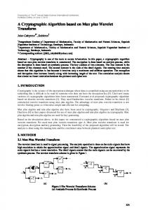
In [11], the authors proposed a method respecting three remedies to reinforce the weakness of security causes by degradation of digital PWLCM: (i) cascading multiple chaotic systems (ii) perturbing the output sequences generated and (iii) using maximum precision of input/output variables of chaotic maps. A qualitative comparison of these remedies is provided in [20]. Authors propose to cascade two output sequences of P W LCM and to apply a perturbation to the last k bits by using LF SR. The results of the two perturbed P W LCM (R1 , R2 ) is combined with a XOR operation in order to produce a new chaotic stream with higher randomicity (R). R is then combined with the plain text M using a XOR operation. So the encrypted data will be given by C = M ⊕ R. Sharing the initial conditions (The Keys), the receiver can generate the same random sequences (R1 , R2 ), compute R and decrypt the received data since XOR is a symmetric operation by computing: M = C⊕R = (M ⊕R)⊕R. Figure 1 represents the operations on both the sender and receiver sides. Perturbed Perturbed P W LCM1 P W LCM2 R1
Perturbed Perturbed P W LCM1 P W LCM2
R2
R1
R Plaintext M
R2 R
Ciphertext C
Ciphertext C Channel
Source
Plaintext M
Destination
(2)
Figure 1: The main encryption/decryption operations of the chaos based algorithm.
The basis of perturbation is to break any stable cycle. Once the P W LCM output has entered a periodic cycle, it can leave
The pseudo-algorithm in 4 represents the essential functions of the encryption/decryption operation of the chaos based algo-
x(n) = 0.x1 (n).x2 (n)...xi (n)...xN (n), such as xi (n) ∈ {0, 1} and i = 1, 2, ..., N
rithm. This function takes as an entry 128bytes of data. The encryption/decryption operation includes 2 major functions: P W LCM for the generation of a pseudo-random numbers Xi in [0, 1], and LF SR used to perturb the Xi for obtaining Ri . The f or loop processes the table InputBytes 2bytes at a time. For each 2bytes of data, 2 pseudo-random numbers are generated and perturbed (R1 , R2 ). It should be noted that due to the limited capabilities of the MSP420 micro-processor used on the TelosB motes, floats and integers do not exceed 2bytes. R1 and R2 are decimal numbers with 6 decimals places, they are then multiplied by 106 and put in 2-byte integer N B1 and N B2 . Finally, the encryption/decryption is done through a XOR between, on one hand, the 2bytes of data and, on the other hand, the result R of a XOR between the integers N B1 and N B2 . Algorithm 4 Encryption/decryption function of chaos based algorithm: EncryptChaos Require: InputBytes[128] X0 ← 0.950347, Y0 ← 0.567217, p1 ← 0.372134, p2 ← 0.292134, ∆ ← 30, Q1 ← Q2 ← 32768, N bIter ← 0 for i = 0 → 128 step 2 do Xi ← P W LCM (Xi , p1 ) Yi ← P W LCM (Yi , p2 ) N bIter ← N bIter + 1 if N bIter%∆ = 0 then R1 ← LF SR(Xi , Q1 ) R2 ← LF SR(Yi , Q2 ) end if N B1 [2] ← R1 N B2 [2] ← R2 OutputBytes(i i + 1) ← InputBytes(i (N B1 ⊕ N B2 ) end for return OutputBytes[128]
main focus is given to the results of the real measurments on TelosB motes. These motes use a 16-bit 8M Hz TI MSP430 micro-processor. The same code that was flashed on the motes is executed on a computer with a Pentium dual-core CPU T4200 at a 2GHz speed in order to analyse the result of the encryption operations. We used Matlab to execute the code. As an indicator, we added the execution time of both algorithms using Matlab. A. Comparison of the speed of encryption In this section, we focus on the execution time of both algorithms. We calculated the time needed for both algorithms to encrypt 128bytes of plain text. As the table I shows, the time needed to encrypt or decrypt 128bytes using the chaos based algorithm is 847 % faster than the time needed using the AES-CTR algorithm, and that on the TelosB motes. It should also be noted that the initialisation phase of AES-CTR takes additional 1, 92seconds on the before mentioned computer and 12, 27seconds on the TelosB motes. Matlab TelosB Matlab TelosB
(128 bytes) (128 bytes) (1 byte) (1 byte)
AES-CTR 132,32 1631,4 1,03 12,74
Chaos 46,25 193,2 0,36 1,5
Table I: Execution time in milliseconds of AES-CTR and chaos based algorithms.
i + 1) ⊕
We must also note that the generator key is composed of: (i) the two initial values (X0 , Y0 ) and their parameters (p1 , p2 ) for the P W LCM map (we have fixed these values randomly), and (ii) the degree L of the two LF SR used for perturbation. If N is the finite precision corresponding to the word length of the processor, the secret key have 22(2N −1)+2L combinations. In our implementation on TelosB motes, we have N = 16 and L = 16 (due to the capability of the micro-processor which does not offer double precision floats). In this case, the space key is 294 which offers a good level of security on this kind of motes.1 In addition, a modification by 10−20 of the initial value of chaotic maps, will lead after some iterations to completely different iterative numbers. IV. R ESULTS OF IMPLEMENTATION We evaluated AES-CTR and the chaos based algorithms in terms of excution time and quality of encryption. The 1 Ideally, we should have N = 32 and L = 17, the key space will be 2160 which satisfies the general requirement of keys length in symmetric cryptographic systems.
As detailed in III, the main functions of the chaos based algorithm are P W LCM and LF SR. Table II shows the time needed in milliseconds to execute those functions. Notice that the LF SR function takes more time to be executed but this is a necessary step in order to avoid loops in the P W LCM function. We chose to apply the LF SR function once every 30 iterations of P W LCM .
Matlab TelosB
PWLCM (N = 16bits) 0.031 0.75
LFSR (L = 16bits, ∆ = 30) 0.71 1.83
Table II: Execution time in milliseconds of the main functions of the chaos based algorithm. B. Image resemblance In order to evaluate the quality of encryption, we used the entry for both algorithms and we calculated the degree of resemblance between the plain image and the encrypted image. Indeed, we used the well known image of Lenna. For simplicity reasons, we chose a black and white image of Lenna. 1) Encryption results: We chose to apply our evaluation on a 128 × 128-pixel image of Lenna. Each pixel is coded on 1byte. Hence, the total image size is 16384 bytes. TelosB motes use the IEEE 802.15.4 frame format which is limited to 133bytes [21] per frame. Thus, in order to transmit the entire Lenna image it will be fragmented into multiple frames.
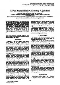
For simplicity reasons, we divided the image into fragments of 128bytes, which means that the entire image will be transmitted over 128f rames. Figure 2 shows the plain image on 2a, the encrypted image using AES-CTR on 2b and the encrypted image using the chaos based algorithm on 2c. It is obvious that both algorithms succeed in hiding the plain image.
250 200 150 100 50
0 0
20
0
50
100
150
200
250
(a) Histogram of plain image
40 60
100
100
80
80
60
60
40
40
20
20
80 100 120 0
50
100
(a) Plain Image 0
0
0
0 0
20
20
40
40
60
60
80
80
100
100
120 0
50
100
150
200
250
0
50
100
150
200
250
(b) Histogram of encrypted image us-(c) Histogram of encrypted image using AES-CTR ing chaos based algorithm
Figure 3: The distribution of color values above the grayscale colorbar of Lenna image encrypted with AES-CTR (3b) and chaos based algorithm (3c).
120 50
100
0
50
100
(b) Encrypted image using AES-(c) Encrypted image using chaos CTR based algorithm
Figure 2: The result of Lenna image encrypted with AES-CTR and chaos based algorithm.
300 250
In order to evaluate the intensity of the pixels of the 3 images, we show in figure 3 the distribution of color values above the grayscale colorbar. As figures 3b and 3c show, the colors are uniformly distributed using the AES-CTR and the chaos based algorithms. 2) Correlation coefficient: Another method to evaluate the quality of the encryption is to measure the correlation factor between adjacent pixels. In figure 4, each point on the X-axis represents a pixel value between 0 and 255. The Y-axis shows the value of the adjacent pixel on the X-axis. It is easy to notice that the values of adjacent pixels in the plain image are highly correlated whereas the values of adjacent pixels in the encrypted images are not correlated as shown on figures 4a, 4b and 4c. The correlation coefficient is another important factor that shows the overall correlation between horizontally, vertically or diagonally adjacent pixels of an image. It is the measure of extent and direction of linear combination of two adjacent pixels. If two pixels are closely related with stronger association, the correlation coefficient is close to either 1 or −1. On the other hand, if the coefficient is close to 0, two pixels are not related and cannot predict each other. The coefficient rx y can be calculated using the formulas given in 5, 6, 7, and 8 where x and y are two adjacent pixels:
200 150 100 50 0 0
50
100
150
200
250
300
(a) Adjacent pixels of plain image 300
300
250
250
200
200
150
150
100
100
50
50
0 0
50
100
150
200
250
300
0 0
50
100
150
200
250
300
(b) Adjacent pixels of encrypted image(c) Adjacent pixels of encrypted image using AES-CTR using chaos based algorithm
Figure 4: The correlation factor between adjacent pixels of Lenna image encrypted with AES-CTR 4b and chaos based algorithm 4c.
E(x) =
D(x) =
1 N
N X
xi
(5)
N 1 X cov(x, y) = (xi − E(xi ))(yi − E(yi )) N i=1
cov(x, y) p rxy = p D(x) D(y)
Horizontal 0.9193 0.0130 -0.0037
Vertical 0.8724 0.0250 0.0321
V. (7)
(8)
Diagonal 0.8409 0.0261 0.0262
Table III: Correlation coefficients of the AES-CTR and the chaos based algorithms. 3) NPCR and UACI: NPCR (Number of Pixels Change Rate) and UACI (Unified Average Changing Intensity) are calculated to test the difference between the plain and the encrypted image. NPCR denotes the percentage of the number of different pixels between the original and the encrypted image. UACI denotes the average intensity of differences between the plain and the encrypted image. Consider C1 (plain image) and C2 (encrypted image). Let the grayscale values of the pixels at position (i, j) be C1 (i, j) and C2 (i, j) of the two images C1 and C2 respectively. Define an array D with the same size as C1 and C2 . Then D(i, j) = 1 if C1 (i, j) = C2 (i, j) and D(i, j) = 0 otherwise. The formulas of NPCR and UACI are given in equations 9 and 10 respectively. P ij D(i, j) × 100 (9) N P CR = M ×N M−1 −1 X NX |C1 (i, j) − C2 (i, j)| 1 × 100 M × N i=0 j=0 255 (10) The optimal values of these parameters are: N P CRopt = 99.61% and U ACIopt = 33.46% [22]. Table IV shows that the values of parameters for both algorithms are close to optimal values. Both algorithms achieve similar NPCR and UACI rates.
U ACI =
UACI 32.9589 32.9541
(6)
Table III shows that the chaos based algorithm has a better horizontal correlation coefficient. The mean correlation coefficient for the AES-CTR is 0, 021, while that of the chaos based algorithm is 0, 02. Hence, we can conclude that AESCTR and the chaos based algorithm have very similar results. It should also be noted that we divided the image into 128byte fragments in a horizontal manner, and thus the encryption operation are applied in a horizontal manner on the pixels.
Initial AES Chaos
NPCR 99.6094 99.6765
Table IV: NPCR and UACI tests for both AES-CTR and chaos based algorithms.
i=1
N 1 X (xi − E(xi ))2 N i=1
AES Chaos
CONCLUSION
Security aspects in wireless sensor networks is becoming more and more important since these networks are being considered for critical applications. Cryptographic algorithms fail to achieve a good security level while maintaining a low execution time. Standards such as AES are robust and provide high level of security but are also very time consuming and do not fit the low capacities of sensor motes. New protocols should be conceived to provide the wireles sensor networks domain with less complex and efficient algorithms. In this paper, we evaluated the performance of a new chaos based algorithm and compared it to the well known AES-CTR algorithm. Results have shown the superiority of the chaos based algorithm in terms of processing time while achieving very comparable results in terms of quality of encryption. Our future works will focus on the energy and memory consumption of the chaos based algorithm and its robustness against attacks like brute force decryption. R EFERENCES [1] P. Ganesan, R. Venugopalan, P. Peddabachagari, A. Dean, F. Mueller, and M. Sichitiu, “Analyzing and modeling encryption overhead for sensor network nodes,” in Wireless Sensor Networks and Applications, 2003. [2] ——, “Evaluation of security mechanisms in wireless sensor networks,” in Systems Communications, 2005. [3] T. Kavitha1 and D. Sridharan, “Security vulnerabilities in wireless sensor networks: A survey,” Journal of Information Assurance and Security, vol. 5, pp. 31–44, 2010. [4] A. Perrig, R. Canetti, J. Tygar, and D. Song, “Efficient authentication and signing of multicast streams over lossy channels,” in IEEE Symposium on Security and Privacy, April 2000. [5] A. Perrig, R. Szewczyk, , V. Wen, D. Culler, and J. Tygar, “SPINS: Security suite for sensor networks,” Proceedings of the Seventh Annual International Conference on Mobile Computing and Networking (MOBICOM-01), pp. 189–199, July 2001. [6] “Advanced encryption standard,” U.S. DoC/NIST, Tech. Rep., November 2001. [7] D. Xiao, F. Shih, and X. Liao, “A chaos-based hash function with both modification detection and localization capabilities,” Communications in Nonlinear Science and Numerical Simulation, vol. 15, pp. 2254–2261, 2010. [8] L. Zhang, X. Liao, and X. Wang, “An image encryption approach based on chaotic maps,” Chaos, Solitons & Fractals, vol. 24, pp. 759–765, 2005. [9] G. Jakimoski and L. Kocarev, “Chaos and cryptography: Block encryption ciphers based on chaotic maps,” IEEE Transactions on Circuits and Systems I: Fundamental Theory and Applications, vol. 48, pp. 163–169, 2001. [10] S. Li, X. Mou, Y. Cai, Z. Ji, and J. Zhang, “On the security of a chaotic encryption scheme: problems with computerized chaos in finite computing precision,” Computer physics communications, vol. 153, pp. 52–58, 2003. [11] B. Bakhache, J. Ghazal, and S. El Assad, “Enhancement of zigbee and wi-fi security by a robust and fast chaotic algorithm,” in 5th International Conference on Network and System Security (NSS), 2011, pp. 300–304. [12] Crossbow, “TelosB datasheet,” document Part Number: 6020-0094-01 Rev B.
[13] Zigbee, “Zigbee Specification,” ZigBee Standards Organization, Zigbee Standard 053474r17, January 2008. [14] HART Communication Foundation Std., “HART field communication protocol specifications,” Tech. Rep., 2008. [15] International Society of Automation Std., “ISA100.11a:2009 wireless systems for industrial automation: Process control and related applications,” Draft standard, in preparation, 2009. [16] “Recommendation for block cipher modes of operation, methods and techniques,” U.S. DoC/NIST, Tech. Rep., December 2001. [17] H. Lee, K. Lee, and Y. Shin, “Aes implementation and performance evaluation on 8-bit microcontrollers,” International Journal of Computer Science and Information Security, vol. 6, pp. 70–74, October 2009. [18] Q. He, Q. Qi, Y. Zhao, W. Huang, and Q. Huang, “The application of chaotic encryption in industrial control based on zigbee wireless network,” in 2nd international symposium on systems and control in aerospace and astronautics ISSCAA, 2008. [19] ——, “Design of one-dimensional chaotic maps with prescribed properties,” International Journal of Bifurcation and chaos, vol. 5, pp. 1585– 1598, 1995. [20] S. Li, G. Chen, and X. Mou, “On the dynamical degradation of digital piecewise linear chaotic maps,” International Journal of Bifurcation and Chaos, vol. 15, pp. 3119–3151, 2005. [21] IEEE 802.15, “Part 15.4: Wireless medium access control (MAC) and physical layer (PHY) specifications for low-rate wireless personal area networks (WPANs),” ANSI/IEEE, Standard 802.15.4 R2006, 2006. [22] Y. Wang, K. Wong, X. Liao, X. T., and C. G., “A chaos-based image encryption algorithm with variable control parameter,” Chaos, Solitons & Fractals, vol. 41, pp. 1773–1783, 2009.