c 2003. This paper will appear in Proceedings of Second International Workshop on Copyright ° Biomedical Image Registration (WBIR 2003) and is made available as an electronic preprint. One print or electronic copy may be made for personal use only. Systematic or multiple reproduction, distribution to multiple locations via electronic or other means, duplication of any material in this paper for a fee or for commercial purposes, or modification of the content of the paper are prohibited.
Evaluation of Intensity-Based 2D-3D Spine Image Registration Using Clinical Gold-Standard Data Daniel B. Russakoff1,2 , Torsten Rohlfing2 , Anthony Ho3 , Daniel H. Kim2 , Ramin Shahidi2 , John R. Adler, Jr.2,3 , and Calvin R. Maurer, Jr.2 1
Department of Computer Science Image Guidance Laboratories, Department of Neurosurgery 3 Department of Radiation Oncology Stanford University, Stanford, CA, USA
[email protected],
[email protected]
2
Abstract. In this paper, we evaluate the accuracy and robustness of intensity-based 2D-3D registration for six image similarity measures using clinical gold-standard spine image data from four patients. The goldstandard transformations are obtained using four bone-implanted fiducial markers. The three best similarity measures are mutual information, cross correlation, and gradient correlation. The mean target registration errors for these three measures range from 1.3 to 1.5 mm. We believe this is the first reported evaluation using clinical gold-standard data.
1
Introduction
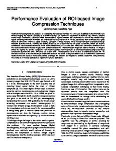
In order to use preoperatively acquired three-dimensional (3D) images for intraoperative therapy guidance, the images must be registered to a patient coordinate system defined in the operating room. Image-to-physical registration is one of the fundamental steps in all image-guided interventions. Surgical navigation systems use the image-to-physical registration transformation to track in real time the changing position of a surgical probe on a display of the preoperative images or to direct a needle to a surgical target visible in the images. Stereotactic radiotherapy and radiosurgery systems use the image-to-physical transformation to direct radiation to a surgical target visible in the images. A promising method for obtaining the image-to-physical transformation is the registration of a 3D x-ray computed tomography (CT) image to one or more twodimensional (2D) x-ray projection images (e.g., fluoroscopy images, amorphous silicon detector images). This approach has applications in image-guided spine surgery [1, 2] and radiosurgery [3, 4]. The 2D-3D registration problem involves taking one or more x-ray projection (2D) images of the patient’s anatomy and using these projections to determine the rigid transformation T (rotation and translation) that aligns the coordinate system of the CT (3D) image with that of the x-ray projection images and the operating room. Figure 1 shows a schematic 1
Optimizer
CT data
Processing (Floating Image)
Rigid Transform
Similarity Measure Processing (Reference Image)
Intra-operative image
Fig. 1. Schematic overview of the 2D-3D registration process. For intensity-based 2D3D registration, the reference image is an intra-operative x-ray projection (2D) image. It is used as is with little or no processing. The floating image is a CT (3D) image. It is processed by generating DRRs (synthetic x-ray projection images) for various orientations of the CT image relative to the reference frame of the x-ray imaging system. The optimizer searches for the rigid transformation T that produces the DRR that is most similar to the real x-ray projection image. The optimal transformation is used to align the CT coordinate system with that of the operating room.
representation of the 2D-3D registration process. In general, most of the proposed solutions to this problem fit into this framework. We are particularly interested in intensity-based 2D-3D image registration [2, 5–7]. In this case, the reference image is one or more x-ray projection images and the floating image is a CT image. The method involves computing synthetic x-ray images, which are called digitally reconstructed radiographs (DRRs), by casting rays using a known camera geometry through the CT image. The DRR pixel values are simply the summations of the CT values encountered along each projection ray. The pose (position and orientation) of the CT image (given by the transformation T) is adjusted iteratively until the DRR produced is most similar to the x-ray projection image. Figure 2 shows a corresponding pair of real and synthetic x-ray projection images. A variety of similarity measures have been used, including cross correlation, pattern intensity, gradient correlation, gradient difference, entropy, and mutual information [6]. Intensity-based 2D-3D image registration appears to be more accurate than feature-based registration (not including metal fiducial markers) [8]. But for spine images, intensity-based 2D-3D registration methods are very susceptible to local minima in the cost function and thus need initial transformations that are close to the correct transformation in order to converge reliably [6]. Also, intensity-based registration methods are basically untested on gold-standard clinical spine image data. In this paper, we evaluate the accuracy and robustness of intensity-based 2D-3D registration for the six aforementioned image similarity measures using clinical gold-standard spine image data from four patients. The gold-standard 2
(a)
(b)
Fig. 2. (a) Example x-ray projection image. A box delineates a region of interest (ROI). Three bone-implanted fiducial markers can be seen in the ROI. (b) A DRR (synthetic projection image) generated from a registered (the correct position and orientation have already been calculated) CT image of the same patient using the camera geometry of the x-ray imaging system used to create the image in (a).
transformations are obtained using four bone-implanted fiducial markers. We believe this is the first reported evaluation using clinical gold-standard data.
2
Gold-Standard Clinical Spine Image Data
The CyberKnife Stereotactic Radiosurgery System (Accuray, Inc., Sunnyvale, CA) is an image-guided frameless robotic stereotactic radiosurgery system that was developed as a noninvasive means to precisely align treatment beams with targets [9]. Two orthogonal amorphous silicon detector (ASD) x-ray cameras in the treatment room establish a coordinate frame to locate the patient’s target site with respect to the therapy beam directions for the robotic manipulator (Fig. 3). A pair of images from the camera system determines the patient’s position during treatment. Because the treatment position can differ from the position in the CT planning study, a 2D-3D image registration process is used to find the rigid-body transformation that relates the CT position to the treatment position. This transformation is communicated through a real-time control loop to a robotic manipulator that points a compact 6 MV x-band linear accelerator (LINAC). By taking images throughout the treatment process, shifts in patient position can be detected and the beams can be redirected accordingly. Patients are currently undergoing treatment of spinal cord lesions with the CyberKnife through an extended FDA treatment protocol for use of the device. Before treatment, each patient is fitted with a simple immobilization device. The cervical spine patients are fitted with a molded Aquaplast face mask 3
X-ray sources
Patient ASD #1
ASD #1
ASD #2
ASD #2 (a)
(b)
Fig. 3. (a) Schematic illustration of the CyberKnife system looking towards the head of a patient lying on the treatment table. Two x-ray sources are mounted on the ceiling. Two amorphous silicon detector (ASD) x-ray cameras are mounted on the floor. The orthogonal x-ray projection imaging system is calibrated so that the intrinsic and extrinsic cameras parameters of both imaging devices are known. The dashed lines indicate the triangulation of the 3D position of a fiducial marker that appears in both x-ray projection images. (b) A birds-eye view of the system showing a patient lying on the treatment table with two x-ray projection images. In these images, the fiducial markers appear as small, white dots in the cervical vertebrae near the base of the skull.
(WFR/Aquaplast Corp., Wyckoff, NJ) that stabilizes the head and neck on a radiographically transparent headrest. Thoracic and lumbar spine patients rest in a conformal alpha cradle during CT imaging and treatment. These supports maintain the general orientation of the anatomy and minimize patient motion. For each patient, a contrast CT scan of the region of interest is acquired for treatment planning and also for reference in the image-guidance process. For spinal radiosurgery of thoracic and lumbar vertebrae, and most cervical vertebrae, fiducial markers are implanted percutaneously before CT scanning in the posterior bony elements of the vertebral levels adjacent to the lesions to provide radiographic landmarks. Because these implanted fiducials have a fixed relationship with the bone in which they are implanted, any movement in the vertebrae is detected and compensated by the CyberKnife. Implantation of fiducial markers occurs in the operating room under conscious sedation. The fiducial markers are 2 × 6 mm surgical stainless steel self-retaining tacks. Four or more fiducials are placed in a noncoplanar pattern and spaced approximately 25 mm apart. Three non-collinear fiducials are required to define a rigid-body transformation. Four fiducials provide redundancy in the event that one of them is obscured or otherwise difficult to image. Each fiducial is implanted through 4
stab wounds in the skin and guided with intraoperative fluoroscopy. They are implanted in the lamina or facet of the spine around the lesion of interest. No complications have been reported from this procedure, and all patients have been discharged home the same day. We obtained archived CyberKnife spinal image data from four patients. Two of these patients have cervical vertebrae lesions (C3 and C5) and two have thoracic vertebrae lesions (T1 and T8). For each patient, we obtained: 1) A pretreatment CT image with slice thickness 1.25 mm and a field of view sufficiently large to image the entire cross section of the body. 2) Approximately 20–30 pairs of orthogonal projection x-ray images obtained at intervals of approximately 60 seconds for the duration of treatment with the two Flashscan 20 flat-panel amorphous silicon x-ray cameras (dpiX, LLC, Palo Alto, CA). The x-ray images have 512 × 512 pixels with pixel size 0.4 mm and 12-bit intensity values. Only one randomly chosen pair of projection x-ray images is used for the work reported in this paper. 3) The camera calibration model and parameters for the two x-ray cameras. These parameters are obtained by scanning a calibration phantom as part of regular quality assurance testing. 4) Positions (3D) of the four fiducial markers in the CT image. 5) Positions (2D) of the four fiducial markers in the projection x-ray images. 2.1
Assessment of Registration Accuracy and Robustness
A gold-standard reference transformation is determined as follows. Each pair of corresponding 2D projection x-ray fiducial positions is backprojected to reconstruct the 3D fiducial position. The rays do not generally intersect. We take as the 3D coordinate the midpoint of the shortest line segment between the two rays. Then we perform a point-based registration by finding the rigid transformation that aligns the 3D fiducial positions from the CT image with the 3D backprojected fiducial positions from the x-ray images, such that the distance between corresponding points is minimized in the root-mean-square sense. The target registration error (TRE) of a registration transformation being evaluated is computed as the difference between the positions of a target mapped by the evaluated transformation and the gold-standard transformation [10]. The TRE values are computed for each voxel inside a rectangular box bounding the vertebra.
3
2D-3D Image Registration Algorithm
The algorithm searches for the six parameters of the rigid transformation that produces the DRR (synthetic x-ray projection image) that is most similar to the real x-ray projection image. The algorithm performs four main functions corresponding to the four shaded boxes in Fig. 1: processing of the reference image, processing of the floating image, computation of a similarity measure, and optimization. 5
3.1
Reference image
We crop the reference image to include a specific region of interest (ROI) (Fig. 2). The ROI includes the anatomy that will be treated. Restricting the registration to a ROI has several advantages. First, this speeds up the registration process. In particular, DRRs are computationally expensive to create, and their generation is typically a bottleneck in the execution of the registration process. The DRRs are generated only for the ROI. Also, the similarity measure is computed only for the ROI. Second, the registration should be more accurate within the ROI. The smaller the ROI, the less likely that structures within the ROI have moved relative to each other between the time the preoperative CT is acquired and the time the procedure is performed. The definition of the ROI is performed manually and requires minimal effort. We generally specify an ROI that includes a vertebra of interest plus the two adjacent vertebra. 3.2
Floating image
A DRR (synthetic x-ray projection image) is generated for each transformation considered during the iterative search process. We use a light field rendering method to generate the DRRs. Using light fields allows most of the computation to be performed in a preprocessing step. After this precomputation step, very accurate DRRs can be generated quickly (about 50 ms for a 256 × 256 DRR). The details can be found in Ref. [11]. 3.3
Image similarity measures
We perform registrations using the six image similarity measures that are described and used in Penney et al. [6]. Specifically, the six similarity measures are: cross correlation, pattern intensity, gradient correlation, gradient difference, difference image entropy, and mutual information. 3.4
Optimization strategy
We currently use a fairly simple best neighbor search strategy similar to that in Ref. [12]. Basically the search process takes an initial transformation T0 as input. The twelve closest neighbors in parameter space are computed by varying each transformation parameter by some given step size. There are twice as many neighbors as parameters because the step size is both added and subtracted in order to look in both directions. Each neighbor Ti is itself a transformation and is evaluated by generating DRRs using Ti and the geometry of each x-ray camera and computing the similarity between the DRRs and the reference x-ray projection images. The neighbor with the best value of the cost function is picked, its neighbors examined, and so on until no further improvement in the value of the cost function can be made for the current step size. Then the process is repeated using the current best transformation as the initial transformation and a smaller step size, 6
which is half of the previous step size. This continues until some predetermined resolution is reached. The parameter step sizes are normalized using a scaling factor such that for a given step size, the average motion of all projected voxels in the projection plane is approximately equal for all parameters [13]. The search is performed in two passes, the first with smoothed versions of the reference images, and the second with the actual reference images. The reference images are smoothed in the first pass using a Gaussian filter with σ = 1.5 mm. This procedure has the effect of smoothing the cost function in order to help avoid local minima and to produce a good initial transformation for the second step. This is a multi-scale search strategy rather than a multi-resolution search strategy, which we have used in previous 3D-3D image registration work. Because the 2D images have a relatively limited number of pixels, we opt to blur the images and use all of the pixels rather than subsample the images in order to better estimate the joint probability density function and joint entropy. The initial step size for the first pass corresponds to an average motion of projected voxels of 5 mm. This is successively decreased to a final step size of 0.5 mm. The initial and final step sizes for the second pass are 2 mm and 0.1 mm, respectively. During the iterative search process, we use a CT image origin that is centered in the region of interest. The selection of this origin is performed manually and requires minimal effort. For spine image registration, we generally specify an origin that is a point in the center of the vertebral body of interest.
4
Results
Initial transformations were generated by perturbing the gold-standard reference transformation by adding randomly generated rotations and translations. The initial transformations were characterized by computing the TRE for the transformation and grouped into six initial TRE intervals: 0–2, 2–4, 4–6, 6–8, 8–10, and 10–12 mm. For each patient and each similarity measure, 480 registrations were performed, 80 in each of the six misregistration intervals. The TRE value was computed for each registration transformation as the difference between the positions of a target mapped by the evaluated transformation and the goldstandard transformation. The TRE values were computed for each voxel inside a rectangular box bounding the vertebra and then averaged. The registrations were characterized as either “successful” if the TRE < 2.5 mm or “unsuccessful” if the TRE ≥ 2.5 mm. The results are listed in Table 1. The TRE values that are listed are the mean TRE for all successful registrations. The pattern intensity similarity measure has two user-defined parameters, r and σ. We evaluated pattern intensity using several values of these parameters. The results we list in Table 1 are the best results we obtained, and correspond to r = 4 mm (10 pixels) and σ = 10. Based on the results listed in Table 1, mutual information, cross correlation, and gradient correlation outperformed the remaining three similarity measures. The mean TRE ranges from 1.3–1.5 mm for these three similarity measures, and the frequency of unsuccessful registrations ranges from 6–15%. With only 7
Table 1. 2D-3D Spine Image Target Registration Error Similarity TRE (mm) Unsuccessful Measure Pat. 1 Pat. 2 Pat. 3 Pat. 4 Mean Max Registrations Mutual Information 1.5 1.7 0.9 1.2 1.3 1.7 6% Cross Correlation 1.3 1.8 1.0 1.7 1.5 1.8 6% Gradient Correlation 2.2 1.0 1.1 1.0 1.3 2.2 15% Pattern Intensity 1.8 1.2 2.0 1.4 1.6 2.0 38% Gradient Difference 2.0 0.9 1.2 1.1 1.3 2.0 23% Diff. Image Entropy 2.1 1.9 2.0 1.7 1.9 2.1 57%
four patients, it is not possible to really distinguish the performance of these three measures from each other. Gradient difference has similar mean and max TRE values, but 23% of the registrations failed. Two of the similarity measures, pattern intensity and difference image entropy, performed substantially worse than the three best measures. The frequency of unsuccessful registrations for these two measures is 38% and 57%, respectively. Figure 4 shows how the percentage of successful registrations depends on the accuracy of the initial transformation. The three best similarity measures based on the results listed in Table 1 are also the three best based on the results shown in this figure. All three measures have a high probability of successful registration as long as the initial transformation has a TRE < 8 mm, with decreasing robustness as the initial transformation gets further from the correct transformation. Pattern intensity and gradient difference have a high probability of successful registration only if the initial transformation has a TRE < 4 mm. Difference image entropy has a poor probability of successful registration regardless of the accuracy of the initial transformation.
5
Discussion
The results in this paper are substantially different than those reported by Penney et al. [6]. For example, we found that mutual information is one of the best similarity measures, whereas they found that it is one of the worst. One possible explanation is that we use higher resolution images in our calculations. As a result, our ROIs have more pixels, which provides more accurate estimates of probability density functions and entropies. We also found that pattern intensity produced relatively poor results with our data, whereas Penney et al. found it to be an accurate and robust measure. We note that the three worst similarity measures in our study, pattern intensity, gradient difference, and difference image entropy, are all computed using a difference image. One of the most important differences between the Penney et al. study and this work is that they used a phantom and we used clinical data. It is possible that different similarity measures produce different results with different kinds of data. It is difficult to make strong conclusions with limited data. The results in this paper are based on image data from only four patients, two with lesions 8
CROSS CORRELATION
90
80 70 60 50 40 30 20
80 70 60 50 40 30 20
10
10
0
0
2
4
6 INITIAL TRE (mm)
8
10
PERCENT CONVERGENCE
100
90
80 70 60 50 40 30 20 10
2
PATTERN INTENSITY
4
6 INITIAL TRE (mm)
8
0
10
90
70 60 50 40 30 20
80 70 60 50 40 30 20
10
10
0
0
4
6 INITIAL TRE (mm)
8
10
PERCENT CONVERGENCE
100
90
80
4
6 INITIAL TRE (mm)
8
10
DIFF. IMAGE ENTROPY
100
90
2
2
GRADIENT DIFFERENCE
100
PERCENT CONVERGENCE
PERCENT CONVERGENCE
GRADIENT CORRELATION
100
90 PERCENT CONVERGENCE
PERCENT CONVERGENCE
MUTUAL INFORMATION 100
80 70 60 50 40 30 20 10
2
4
6 INITIAL TRE (mm)
8
10
0
2
4
6 INITIAL TRE (mm)
8
10
Fig. 4. Percentage of successful registrations for initial transformations with different initial TRE values for six image similarity measures. Each data point represents a 2 mm range of initial TRE values centered at the x-coordinate.
in cervical vertebrae and two with lesions in thoracic vertebrae. We have access to clinical gold-standard image data from at least twenty additional patients and plan to analyze this data in the future. These patients have spinal lesions at vertebral locations distributed throughout the spinal column, including the lumbar region.
Acknowledgments DBR was supported by the Interdisciplinary Initiatives Program, which is part of the Bio-X Program at Stanford University, under the grant “Image-Guided Radiosurgery for the Spine and Lungs.” TR was supported by the National Science Foundation under Grant No. EIA-0104114. The authors thank John Dooley, Gopinath Kuduvalli, and Matt Core (Accuray, Inc., Sunnyvale, CA) for their technical assistance.
References 1. S. Lavallee, J. Troccaz, P. Sautot, B. Mazier, P. Cinquin, P. Merloz, and J.-P. Chirossel, “Computer-assisted spinal surgery using anatomy-based registration,” in Computer-Integrated Surgery: Technology and Clinical Applications, R. H. Taylor, S. Lavallee, G. Burdea, and R. M¨ osges, Eds. Cambridge, MA: MIT Press, 1996, pp. 425–449.
9
2. J. Weese, G. P. Penney, T. M. Buzug, D. L. G. Hill, and D. J. Hawkes, “Voxelbased 2-D/3-D registration of fluoroscopy images and CT scans for image-guided surgery,” IEEE Trans. Inform. Technol. Biomedicine, vol. 1, pp. 284–293, 1997. 3. M. J. Murphy, J. R. Adler, Jr., M. Bodduluri, J. Dooley, K. Forster, J. Hai, Q. Le, G. Luxton, D. Martin, and J. Poen, “Image-guided radiosurgery for the spine and pancreas,” Comput. Aided Surg., vol. 5, pp. 278–288, 2000. 4. S. I. Ryu, S. D. Chang, D. H. Kim, M. J. Murphy, Q.-T. Le, D. P. Martin, and J. R. Adler, Jr., “Image-guided hypo-fractionated stereotactic radiosurgery to spinal lesions,” Neurosurgery, vol. 49, pp. 838–846, 2001. 5. L. Lemieux, R. Jagoe, D. R. Fish, N. D. Kitchen, and D. G. T. Thomas, “A patient-to-computed-tomography image registration method based on digitally reconstructed radiographs,” Med. Phys., vol. 21, pp. 1749–1760, 1994. 6. G. P. Penney, J. Weese, J. A. Little, P. Desmedt, D. L. G. Hill, and D. J. Hawkes, “A comparison of similarity measures for use in 2D-3D medical image registration,” IEEE Trans. Med. Imaging, vol. 17, pp. 586–595, 1998. 7. G. P. Penney, P. G. Batchelor, D. L. G. Hill, and D. J. Hawkes, “Validation of a two- to three-dimensional registration algorithm for aligning preoperative CT images and intraoperative fluoroscopy images,” Med. Phys., vol. 28, pp. 1024–1032, 2001. 8. R. A. McLaughlin, J. Hipwell, D. J. Hawkes, J. A. Noble, J. V. Byrne, and T. C. S. Cox, “A comparison of 2D-3D intensity-based registration and feature-based registration for neurointerventions,” in Medical Imaging Computing and ComputerAssisted Intervention (MICCAI) 2002, T. Dohi and R. Kikinis, Eds. Berlin: Springer-Verlag, 2002, pp. 517–524. 9. J. R. Adler, Jr., M. J. Murphy, S. D. Chang, and S. L. Hancock, “Image-guided robotic radiosurgery,” Neurosurgery, vol. 44, pp. 1299–1307, 1999. 10. J. B. West, J. M. Fitzpatrick, M. Y. Wang, B. M. Dawant, C. R. Maurer, Jr., R. M. Kessler, R. J. Maciunas, et al., “Comparison and evaluation of retrospective intermodality image registration techniques,” J. Comput. Assist. Tomogr., vol. 21, pp. 554–566, 1997. 11. D. B. Russakoff, T. Rohlfing, D. Rueckert, R. Shahidi, D. Kim, and C. R. Maurer, Jr., “Fast calculation of digitally reconstructed radiographs using light fields,” Medical Imaging 2003: Image Processing, vol. Proc. SPIE 5032, 2003 (in press). 12. C. Studholme, D. L. G. Hill, and D. J. Hawkes, “Automated three-dimensional registration of magnetic resonance and positron emission tomography brain images by multiresolution optimization of voxel similarity measures,” Med. Phys., vol. 24, pp. 25–35, 1997. 13. T. Rohlfing, D. B. Russakoff, M. J. Murphy, and C. R. Maurer, Jr., “An intensitybased registration algorithm for probabilistic images and its application for 2-D to 3-D image registration,” Medical Imaging 2002: Image Processing, vol. Proc. SPIE 4684, pp. 581–591, 2002.
10