Evaluation of SysML Diagrams to Document Requirements using TAM Michel S. Soares
Rogério P. C. do Nascimento
Federal University of Sergipe Computer Science Department Aracaju, Sergipe
Federal University of Sergipe Computer Science Department Aracaju, Sergipe
[email protected]
[email protected]
ABSTRACT A number of methods, languages, tools and techniques are widely used in Software Engineering projects even before being formally evaluated in practice. In critical phases of software life cycle, such as requirements engineering, this practice may lead to deceptions. In this paper, an evaluation of the Systems Modeling Language (SysML) diagrams and constructions when applied to requirements engineering activities is proposed. This evaluation was performed based on the Technology Acceptance Model (TAM). Three criteria were used to evaluate the acceptance of SysML as a language for requirements engineering: perceived usefulness, perceived ease of use, and perceived usage. The evaluation was performed in practice in a company that develops software-intensive systems.
Keywords TAM, SysML, Software Requirements.
1. INTRODUCTION Application of unevaluated methods, languages, tools and techniques in Software Engineering industry projects’ is common. This practice can lead to a number of related issues, such as lack of confidence on technologies and complete project failures. Unfortunately, for some reasons such as aggressive marketing and decisions taken without adequate knowledge, unevaluated methods and techniques have been routinely used in practice throughout the entire spectrum of requirements, design, implementation and evaluation activities of software development [9] [30]. Requirements Engineering (RE) is considered by some experts the most problematic and difficult phase within the development of software [15] [4] [25]. In specific domains, such as automotive software, RE is considered one of the crucial issues [6]. According to [5], knowing what to build, which includes requirements elicitation and technical specification, is the most difficult phase in the design of software.
Permission to make digital or hard copies of all or part of this work for personal or classroom use is granted without fee provided that copies are not made or distributed for profit or commercial advantage and that copies bear this notice and the full citation on the first page. To copy otherwise, to republish, to post on servers or to redistribute to lists, requires prior specific permission and/or a fee. EATIS’14 April 02 - 04 2014, Valparaiso, Chile Copyright 2014 978-1-4503-2435-9/14/04 ACM http://dx.doi.org/10.1145/2590651.2590661 ...$15.00.
Dealing with ever-changing requirements is considered the real problem of Software Engineering [3]. Some studies [28] [10] found that the main factors for problems with software projects (cost overruns, delays, user dissatisfaction) are related to requirements issues, such as lack of user input, incomplete requirements specifications, uncontrolled requirements changing, and unclear objectives. In this paper we want to evaluate the use of the Systems Modeling Language (SysML) [18] in activities of documenting and analyzing requirements. SysML is chosen mainly because it is a language that provides a specific diagram to model requirements. The SysML Requirements diagram covers important features of RE that are partially addressed or not addressed at all by other techniques [27]. Examples are facilities for traceability between requirements and the modeling of other types of requirements besides the functional ones. Another reason is that SysML is largely based on UML [17], a well-known modeling language and considered the de facto modeling language in industry. SysML has been applied to a number of projects [31] [14] in various fields, such as large telescopes [13], car manufacturing [2], nuclear automation [20], modeling the dynamics of hydraulic pump systems [12], and road traffic management systems [27]. Also, in this paper, SysML diagrams and constructions tailored for activities concerning RE are evaluated in practice in a company that develops software-intensive systems. The novelty of this paper lies on two aspects. First, the paper presents an attempt to evaluate part of SysML, more specifically diagrams and constructions used in requirements engineering activities. Second, the evaluation is performed in practice using TAM [9], a well-known model to evaluate technologies.
2.
SYSML ELEMENTS FOR REQUIREMENTS ENGINEERING
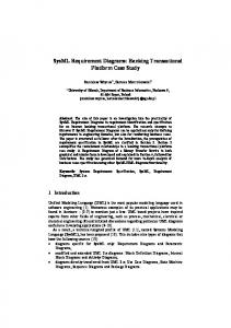
SysML is considered both a subset and an extension of UML [18] (Fig. 1). As a subset, UML diagrams considered too specific for software (Objects and Deployment diagrams) or redundant with other diagrams (Communication and Time Diagrams) were not included in SysML. Some diagrams are derived from UML without significant changes (Sequence, State-Machine, Use Case, and Package Diagrams), some are derived with changes (Activity, Block Definition, Internal Block Diagrams) and two new diagrams were introduced (Requirements and Parametric Diagrams). As a matter of fact, SysML is compatible with UML, which can facilitate the integration of the disciplines of Software and
SysML Diagrams
Behavior Diagrams
Activity Diagram
Sequence Diagram
Requirements Diagrams
State Machine Diagram
Structure Diagrams
Block Definition Diagram
Use Case Diagram
Modified from UML2
Internal Block Diagram
Package Diagram
Parametric Diagram
New diagram Same as UML2
Figure 1: SysML Diagrams and its relation to UML System Engineering. Two diagrams of the SysML language, the Requirements and the Use Case diagrams, and the SysML Tables, are recognized as useful for being used in activities of RE. These constructions are briefly presented in this Section.
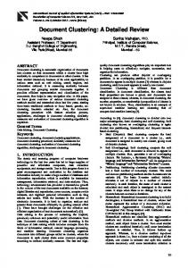
2.1 SysML Requirements Diagram The SysML Requirements diagram is a stereotype of the UML Class diagram, as depicted in Fig. 2. A SysML Requirement can appear on other UML/SysML diagrams to show its relationship to design. With the SysML Requirements diagram, visualization techniques are applied from the early phases of system development. The SysML Requirements diagram allows several ways to represent requirements relationships. These include relationships for defining requirements hierarchy, deriving requirements, satisfying requirements, verifying requirements and refining requirements [18]. The relationships can improve the specification of systems, as they can be used to model and analize requirements.
UML4SysML::Class
main difference is the wider focus, as the idea is to model complex systems that involve not only software, but also other systems, personnel, and hardware. The Use Case diagram shows system functionalities that are performed through the interaction of the system with its actors. The idea is to represent what the system will perform, not how. The diagrams are composed of actors, use cases and their relationships. Actors may correspond to users, other systems or any external entity to the system. One important limitation of Use Cases diagrams is that their focus is on specifying only functional requirements. Non-functional requirements, such as performance, and external requirements, such as interfaces, which are fundamental in software-intensive systems, are not well-represented by Use Case diagrams.
2.3
SysML Requirements Table
SysML allows the representation of requirements, their properties and relationships in a tabular format. One proposed table shows the hierarchical tree of requirements from a master one. The fields proposed for Table 1 are the requirement’s ID, name and type. There is a table for each requirement that has child requirements related by the relationship hierarchy. Table 1: A SysML Hierarchy Requirements table Id Name Type
Requirement - Text: String - Id: String
3.
EVALUATION OF SYSML DIAGRAMS AND TABLES USING TAM
2.2 SysML Use Case Diagram
The research presented in this paper is about Software Engineering, which is a discipline that is most necessary to develop large, complex software. This is most likely to happen in practice, with real world problems. Thus, the choice was to test the hypothesis at an industrial environment.
The SysML Use Case diagram is derived without important extensions from the UML 2.0 Use Case diagram. The
3.1
Figure 2: Basic SysML Requirements diagram
Industry as Laboratory
The industry as laboratory approach uses the actual industrial setting as test environment [21]. Within this approach, the research team builds an intimate relationship with an industrial product creation team, which is mutually beneficial [16]. The research team gets inspiration from real industrial challenges, and at the same time it gets a means to verify research results in industrial settings. The industrial partner gets inspiration from results, and is continuously challenged by unbiased and critical people. The testing was performed at a company specializing in developing software-intensive systems in the field of road traffic management. In practice, the introduction of a new technology in industry is often done by a course. A common format for a course is that an expert from outside the company lecture to the employees. This saves time, as the best practices are already introduced through an experienced person.
3.2 Course on Model-Driven Software Engineering Proposed course was followed by ten employees (all members of the development department), varying from developers to managers. This course had a broad content, including modules about Object-Oriented Modeling with UML, Software Architecture, and Formal Methods, and the content of the module about SysML was as follows: 1. Introduction to SysML 2. SysML Use Cases 3. SysML Requirements diagram 4. SysML Tables 5. SysML Block diagrams This module of the course had two main objectives. The first one was to present the SysML diagrams relevant for the experiment. The emphasis was on the SysML diagrams used for RE, including extensions to the basic SysML Requirements diagram as proposed in [26]. The second objective was to discuss the advantages of combining UML and SysML diagrams for describing software architectural views. During the module the participants had the opportunity to learn the theory combined with examples in a variety of domains. A number of exercises were proposed during the course. The purpose of these exercises was twofold: (i) employees could practice what they have just learnt, and (ii) as an evaluation of the difficulties they had with the modeling languages. The exercises were tailored as entry-level ones, with low level of complexity and considered feasible to be done individually. One example of exercise was to design a SysML requirements diagram based on a list of user requirements.
3.3 Putting SysML to Work After the course, a simple project was proposed by the company to each participant, in which they had to use the knowledge gained during the course to create a design for the project. The project was suitable to be developed individually. After the course and the use of SysML for “toy projects”, the company started to seriously use SysML as a complement to UML in a number of industrial projects. The com-
pany is currently trying to find the best way to incorporate SysML in the company’s development process.
3.4
Evaluation using TAM
Many models have been proposed to explain and predict the use of a system [29]. The most widely employed model of technology adoption and use is the Technology Acceptance Model (TAM) [9] [1]. The model suggests that when users are presented with a new technology, a number of factors influence their decision about how and when they will use it. It posits that individuals’ behavioral intention to use a technology is determined by two beliefs: perceived usefulness, defined as the degree to which a person believes that using the technology will enhance his or her job performance, and perceived ease of use, defined as the degree to which a person believes that using a particular system will be free of effort. A third variable is considered in this paper: perceived usage [1], defined as the degree to which the user will actually use the technology. In this paper we are interested in the individuals acceptance process, which is a good starting point to understand how a new technology might be accepted in a community. Therefore, extensions to TAM in which the social context is taken into account [29], although useful, are not investigated here. In addition, the purpose is to evaluate initial acceptance of technology, which makes TAM a suitable model. TAM was initially proposed to evaluate information systems tools [9] [1], but it has also been used in other contexts, such as to evaluate the adoption of the BPMN notation to teach business process at the university level [24] and the intention to continue using a process modeling technique [22]. Evaluation was performed using two techniques: surveys, based on the TAM theory, and interviews. All the participants that returned the questionnaire had followed the Model-Driven Software Engineering course and had had some practice after making a design for a simple, but realistic, project. Thus, the questionnaire was not proposed as soon as the course ended. Participants answered a questionnaire composed of 11 statements in which they made their opinions explicit. A 5-point Likert scale was proposed to measure perceived attitudes of the employees by providing a range of responses to each statement. The scale ranged from (1) strongly disagree, (2) disagree, (3) neutral, (4) agree, and (5) strongly agree. For the negative statements, it was inferred from low scores that the participants are positive about a statement in the questionnaire, while for the positive statements, a high score was inferred that the participants were positive about the statement. The response categories in Likert scales have rank order, but the intervals between values cannot be presumed equal [11]. As a result, Likert scales fall within the ordinal level of measurement. When treated as ordinal data, Likert responses can be analyzed using non-parametric tests, such as the Mann-Whitney test, the Wilcoxon signed rank test, and the Kruskal-Wallis test [8]. Non-parametric statistical methods were used to analyze the findings because the subjects involved in the study were few and not chosen randomly from a large population. The objective was to find the representative power of the results, and not necessarily the statistical significance. It is worthwhile to note that nonparametric techniques do not solve the problem of potential dependency between the answers of the participants.
4. RESULTS 4.1 Proposed Questionnaire A questionnaire was answered by ten employees. The answers regarding each question are shown in tables 2, 3, and 4, in which “m” represents the mean, “s” represents the standard deviation, and “pos” indicates the number of positive answers, given in modulus because of negative statements. We arbitrarily considered as positive the answers “Agree” or “Strongly Agree” (values 4 or 5). For negative sentences we considered 1 and 2 for a positive response. The answers relative to statements 1 to 4 indicate that the SysML Requirements diagram has potential of usefulness in general. Most respondents considered that the diagram is useful to make the models more expressive and that it improves traceability between requirements and other design models, which is fundamental for designing softwareintensive systems. Even being a UML profile and sharing UML concepts, constructs and diagrams, details related specifically to SysML were not considered easy to understand and use. Moreover, the relationship and the differences between UML and SysML diagrams for RE are not clear. The results of statements 5 to 8 indicate that even for developers that are knowledgeable about UML, a specific training in SysML is highly recommendable. This is reflected in statements 9 to 11, about the usage of SysML. Although there was an interest in knowing more, there was also concern about the acceptance in real projects and the amount of time needed to learn the language.
4.2 Interviews Individual interviews were conducted with some of the participants. The purpose was to better understand the responses and to ask for more details of the process of software development at the company. The focus was on interviewing, when possible, those employees whose answers deviate from the group. For instance, in statement 4, although SysML Requirements diagram was recognized as useful to make models more expressive, and also to facilitate traceability, still most individuals were neutral regarding the improvement of RE activities by using SysML. The main reason for this is related to the introduction of a new modeling language to a well-established modeling process. Thus, training is highly recommended. A major concern mentioned during the interviews was related to the customer and the requirements. That confirms the many publications cited in this paper [3] [4] [25] that consider RE a critical phase in software development. For instance, according to one developer, the customer comes with very specific requirements, making it difficult to change or to adapt. In order to facilitate the implementation, developers may interpret the requirements, which is considered “dangerous” by one manager. Incorrect interpretations may lead to different implementation of certain functionalities and displease the customer. SysML was considered easy to use and almost directly applicable, as it is an extension of UML. Another perceived advantage of SysML is the flexibility provided by the language and the possibility of creating specific profiles with important company-specific additions. Specifically about the SysML Requirements diagram and Tables, developers and managers saw potential in SysML compared to their old re-
quirements specification method, mainly because it clearly shows relations between requirements, and between requirements and design. SysML Requirements diagrams and Tables were already applied to two projects at the company.
5.
ANALYSIS OF FINDINGS
According to many authors [19] [23] [7], gap between new academic methods, techniques and processes and their application in industry is common in Systems and Software Engineering. The challenge is not only to develop better theories, but also to effectively introduce and use these theories in practice. One way to address this gap is to use industry as a testing environment. Thus, researchers learn what real world problems exist, and if the proposed solutions really contribute to solving problems. SysML Requirements diagram may become the language of choice for requirements specification. As SysML is a language, not a methodology, it can be added without many problems into the current development process in an organization. The language can be adapted and integrated into the existing methodology and processes. In addition, SysML is based on UML, which is widely known and used, both in academia and industry. As a matter of fact, SysML is considered easily introduced to teams that are already using UML. The major concern is to find the correct relationship between UML and SysML diagrams. During the course, it became clear that the employees could understand the proposed SysML diagrams of the examples. Finally, although training was mentioned as highly recommended, one has to keep in mind that developers are always very busy and have little time to stop their work and learn new technologies. Formal training, in which groups of employees attend classes, is often not what they prefer. In practice, the learning process is frequently done “on the job”, by interacting with more experienced employees. As a result, informal training, in which one or more employees explain not at once, but daily during the effective execution of real tasks, has more potential to be successful.
6.
CONCLUSIONS
Introduction of new techniques, methods, tools or procedures is challenging in Software Engineering. Not only people are taken out of their comfort zone, but it also takes an effort to adapt legacy systems to the new approaches. As a result, risks may increase, as well as developers dissatisfaction and financial losses. In order to avoid these problems, intensive training is necessary. Common approach for training in many companies is to have a formal course to be held at a specific date and time, followed by everyone at the same time, lectured by an expert. The main issue in this case is the assumption that every person has the same ability to follow the course, which is not true in most cases. The approach followed in this paper has a close relationship with industry, in what is often called “Industry as Laboratory”. This approach offers advantages for both academia and industry. Working in cooperation with partners from industry bring real problems and cases to researchers, and show them what Software Engineering looks like in practice. The effect is that researchers have real challenges to confirm/refute their theories. In addition, their results are stronger when tested in a real industry environment, not only with toy projects. The advantage for industry is that
Table 2: Perceived usefulness of SysML - statements 1 to 4 Statement 1 2 3 4 5 m s 1 - Using the SysML Requirements Diagram will make 2 8 3.8 0.42
pos 8
my models more expressive. 2 - Using the SysML Requirements Diagram relationships will make it easier to trace requirements.
2
7
3 - Using the SysML Requirements Diagram extensions will improve the requirements engineering phase.
4
4 - Using the SysML Requirements Diagram to model all types of requirement will improve the requirements engineering phase.
7
1
3.9
0.56
8
6
3.6
0.51
6
3
3.3
0.48
3
Table 3: Perceived ease of use of SysML - statements 5 to 8 Statement 1 2 3 4 5 m s 5 - It is easy for me to know the difference between 3 5 2 2.9 0.73
pos 2
UML and SysML Use Cases. 6 - It is easy for me to know the difference between each SysML Requirements diagram relationship.
2
6
1
7 - I find it easy to relate SysML Use Cases and SysML Requirements Diagrams.
1
8
8 - It is easy for me to model requirements using the SysML Requirements diagram.
3
3
1
3.1
0.87
2
1
3
0.47
1
4
3.1
0.87
4
Table 4: Perceived usage of SysML - statements 9 to 11 Statement 1 2 3 4 5 m s 9 - I worry about the acceptance of SysML in a real 4 4 2 2.8 0.78
pos 4
project. 10 - I worry about the amount of time needed to learn SysML. 11 - I am interested in knowing more about SysML.
researchers are most likely capable to think “outside the box”, proposing non-conventional solutions that may have high impact on problem solving. The industrial partners gets inspiration from results, and are continuously challenged by unbiased and critical people. SysML language has been applied in many projects, as indicated by a number of publications cited in this paper. These first results are promising, but there is still a long way to go to make SysML acceptable and used as widely for Systems Engineering as UML is for Software Engineering. The challenge is even greater than was the acceptance of UML. With SysML, not only the Software Engineering community has to approve, but also many other engineering communities. As a matter of fact, the first results are promising, but additional evaluation by the research community is needed.
7. REFERENCES [1] D. A. Adams, R. R. Nelson, and P. A. Todd. Perceived Usefulness, Ease of Use, and Usage of Information Technology: a Replication. MIS Quarterly,, 16(2):227–247, 1992. [2] L. Balmelli, D. Brown, M. Cantor, and M. Mott. Model-driven Systems Development. IBM Systems Journal,, 45(3):569–586, 2006. [3] D. M. Berry. The Inevitable Pain of Software Development: Why There Is No Silver Bullet. In
[4]
[5]
[6]
[7]
[8]
7
2
1
2.4
0.7
7
4
6
3.6
0.51
6
Radical Innovations of Software and Systems Engineering in the Future, Lecture Notes in Computer Science, pages 50–74. 2004. A. Birk and G. Heller. Challenges for Requirements Engineering and Management in Software Product Line Development. In REFSQ’07: Proceedings of the 13th international working conference on Requirements engineering, pages 300–305, Berlin, Heidelberg, 2007. Springer-Verlag. F. P. Brooks. No Silver Bullet: Essence and Accidents of Software Engineering. Computer,, 20(4):10–19, 1987. M. Broy. Challenges in Automotive Software Engineering. In ICSE ’06: Proceedings of the 28th international conference on Software engineering, pages 33–42, New York, NY, USA, 2006. ACM. A. M. Connor, J. Buchan, and K. Petrova. Bridging the Research-Practice Gap in Requirements Engineering through Effective Teaching and Peer Learning. In ITNG ’09: Proceedings of the 2009 Sixth International Conference on Information Technology: New Generations, pages 678–683, Washington, DC, USA, 2009. IEEE Computer Society. G. W. Corder and D. I. Foreman. Nonparametric Statistics for Non-Statisticians: A Step-by-Step Approach. John Wiley & Sons, Hoboken, NJ, USA,
2009. [9] F. D. Davis. Perceived Usefulness, Perceived Ease of Use, and User Acceptance of Information Technology. MIS Quarterly,, 13(3):319–339, 1989. [10] H. F. Hofmann and F. Lehner. Requirements Engineering as a Success Factor in Software Projects. IEEE Software,, 18(4):58–66, 2001. [11] S. Jamieson. Likert Scales: How to (ab)use them. Med Educ,, 38(12):1217–1218, 2004. [12] T. A. Johnson, J. M. Jobe, and C. J. J. Paredis. Modeling Continuous System Dynamics in SysML. In ASME 2007 International Mechanical Engineering Congress and Exposition (IMECE2007), volume 3, pages 197–205, 2007. [13] R. Karban, M. Zamparelli, B. Bauvir, B. Koehler, L. Noethe, and A. Balestra. Exploring Model Based Engineering for Large Telescopes: Getting Started with Descriptive Models. In G. Z. Angeli and M. J. Cullum, editors, Modeling, Systems Engineering, and Project Management for Astronomy III, volume 7017, pages 1–13, 2008. [14] R. Laleau, F. Semmak, A. Matoussi, D. Petit, A. Hammad, and B. Tatibouet. A First Attempt to Combine SysML Requirements Diagrams and B . Innovations in Systems and Software Engineering, 6(1):47–54, 2010. [15] O. Minor and J. Armarego. Requirements Engineering: a Close Look at Industry Needs and Model Curricula. Australian Journal of Information Systems,, 13(1):192–208, 2005. [16] G. Muller and P. van de Laar. Researching Reference Architectures and their Relationship with Frameworks, Methods, Techniques, and Tools. In Proceedings of the 7th Annual Conference on Systems Engineering Research (CSER 2009), 2009. [17] OMG. Unified Modeling Language (UML): Superstructure - version 2.3, 2010. [18] OMG. Systems Modeling Language (SysML) - Version 1.3, 2012. [19] D. L. Parnas. Software Engineering: an Unconsummated Marriage. Communications of the ACM,, 40(9):128, 1997. [20] P. Pihlanko, S. Sierla, K. Thramboulidis, and M. Viitasalo. An Industrial Evaluation of SysML: the Case of a Nuclear Automation Modernization Project. In Proceedings of the IEEE International Conference on Emerging Technology and Factory Automation 2013, 2013. IEEE International Conference on Emerging Technology and Factory Automation, 10-13 Sep 2013, Cagliari, Italy. [21] C. Potts. Software-Engineering Research Revisited. IEEE Software,, 10(5):19–28, 1993. [22] J. C. Recker. Why Do We Keep Using A Process Modelling Technique? In Proceddings of the 18th Australasian Conference on Information Systems, 2007. [23] D. J. Reifer. Is the Software Engineering State of the Practice Getting Closer to the State of the Art? IEEE Software,, 20(6):78–83, 2003. [24] T. Rozman, R. V. Horvat, and I. Rozman. Modeling the Standard Compliant Software Processes in the
[25]
[26]
[27]
[28]
[29]
[30]
[31]
University Environment. Business Process Management Journal,, 14(1):53 – 64, 2008. G. Sabaliauskaite, A. Loconsole, E. Engstr¨ om, M. Unterkalmsteiner, B. Regnell, P. Runeson, T. Gorschek, and R. Feldt. Challenges in Aligning Requirements Engineering and Verification in a Large-Scale Industrial Context. In REFSQ, pages 128–142, 2010. M. S. Soares and J. Vrancken. Model-Driven User Requirements Specification using SysML. Journal of Software, 3(6):57–68, 2008. M. S. Soares, J. L. M. Vrancken, and A. Verbraeck. User Requirements Modeling and Analysis of Software-Intensive Systems. Journal of Systems and Software, 84(2):328–339, 2011. M. van Genuchten. Why is Software Late? An Empirical Study of Reasons For Delay in Software Development. IEEE Transactions on Software Engineering,, 17(6):582–590, 1991. V. Venkatesh and H. Bala. Technology Acceptance Model 3 and a Research Agenda on Interventions. Decision Sciences,, 39(2):273–315, 2008. V. Venkatesh, M. G. Morris, G. B. Davis, and F. D. Davis. User Acceptance of Information Technology: Toward a Unified View. MIS Quarterly,, 27(3):425–478, 2003. A. Viehl, T. Sch¨ onwald, O. Bringmann, and W. Rosenstiel. Formal Performance Analysis and Simulation of UML/SysML Models for ESL Design. In DATE ’06: Proceedings of the conference on Design, automation and test in Europe, pages 242–247, 3001 Leuven, Belgium, Belgium, 2006. European Design and Automation Association.