Evidence-based lean logic profiles for conceptual data modelling languages Pablo Rub´en Fillottrania,b , C. Maria Keetc,∗ a Departamento
de Ciencias e Ingenier´ıa de la Computaci´ on, Universidad Nacional del Sur, Bah´ıa Blanca, Argentina b Comisi´ on de Investigaciones Cient´ıficas, Provincia de Buenos Aires, Argentina c Department of Computer Science, University of Cape Town, Cape Town 7701, South Africa. Tel: +27 (0)21 650 2667
arXiv:1809.03001v1 [cs.AI] 9 Sep 2018
Abstract Multiple logic-based reconstruction of conceptual data modelling languages such as EER, UML Class Diagrams, and ORM exists. They mainly cover various fragments of the languages and none are formalised such that the logic applies simultaneously for all three modelling language families as unifying mechanism. This hampers interchangeability, interoperability, and tooling support. In addition, due to the lack of a systematic design process of the logic used for the formalisation, hidden choices permeate the formalisations that have rendered them incompatible. We aim to address these problems, first, by structuring the logic design process in a methodological way. We generalise and extend the DSL design process to apply to logic language design more generally and, in particular, by incorporating an ontological analysis of language features in the process. Second, availing of this extended process, of evidence gathered of language feature usage, and of computational complexity insights from Description Logics (DL), we specify logic profiles taking into account the ontological commitments embedded in the languages. The profiles characterise the minimum logic structure needed to handle the semantics of conceptual models, enabling the development of interoperability tools. There is no known DL language that matches exactly the features of those profiles and the common core is small (in the tractable ALN I). Although hardly any inconsistencies can be derived with the profiles, it is promising for scalable runtime use of conceptual data models. Keywords: Conceptual modelling, modelling languages, language profiles, modelling language use
1. Introduction Many conceptual data modelling languages (CDMLs) have been proposed over the past 40 years by several research communities (e.g., relational databases, object-oriented software) and for a range of motivations, such as spatial entities in geographic information systems, ontology-driven or not, and aiming for simplicity and leanness vs expressiveness. Assessing the modelling features of CDMLs over time, it exhibits a general trend toward an increase in modelling features; e.g., UML has identifiers since v2.4.1 [1], ORM 2 has more ring constraints than ORM [2, 3], and EER also supports entity type subsumption and disjointness cf. ER [4, 5]. Opinion varies about this feature richness and its relation to model quality [6] and fidelity of capturing all the constraints specified by the customer, and asking modellers and domain experts which features they think they use, actually use, and need showed discrepancies between them [7]. From the quantitative viewpoint, it has been shown that advanced features are being used somewhere by someone, but they are used relatively very few times, as both the quantitative analysis of CDML feature usage in 168 ORM diagrams [8], and 101 EER, UML, and ORM diagrams has shown [9]. With such insight into feature usage, it is possible to define an appropriate logic as underlying foundation of a CDML so as to not only clarify semantics but also use it for computational tasks. Logic-based reconstructions open up the ∗ Corresponding
author URL:
[email protected] (Pablo Rub´ en Fillottrani),
[email protected] (C. Maria Keet)
Preprint about to be submitted to an international journal
September 11, 2018
Affiliation has 0..* name: String {ID} 0..3 country: Code Address [0..1]: String affiliated with 0..1
1..* Person name: String {ID} has member 0..n Reviewer reviewed 2..* by
Scientist
Copy editor
written by 1..*
has member 0..*
1..* edited by
writes 0..* 0..* reviews
1..* Popular Science book edits
Book 0..* title: String publishes ISBN: String {ID}
Publisher 1 name: String published VAT reg no: Code {ID} by HQ: String
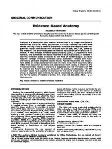
Figure 1: Sample UML Class Diagram containing all possible constraints of the Standard Core Profile, DC s , which emanated from the evidence-based profile specifications.
opportunity for, among others, automated reasoning over a model to improve its quality (e.g., [10, 11]) and runtime usage of the models, such as conceptual and visual query formulation [12, 13, 14] and optimisation of query compilation [15]. Concerning the ‘appropriate’ logic, many logic-based reconstructions have been proposed over the years (discussed below), which can be grouped into either the Description Logics based approach that propose logics from viewpoint of computational complexity, rather than needs and usages by modeller, or the asexpressive-as-needed approach, such as in full first-order predicate logic. Neither of these proposals, however, has taken a methodological approach to language design and brush over several thorny details of CDMLs, such as which core types of elements to formalise with their own semantics (aggregation, association ends), whether to include n-aries (when n ≥ 2, not n = 2), and various advanced constraints. This has resulted into an embarrassment of the riches of logic-based reconstructions, which also hampers the actual use of logicbased conceptual data models in information systems for aforementioned tasks and therewith risk sliding into disuse. We aim to address these problems in this paper. First, we will adapt and extend Frank’s DSL design methodology [16] into one suitable for language design more broadly, including conceptual data modelling languages, and informed by language design decision points emanating from ontology. Such ontology-driven language design decisions include, among others, positionalism of relations, the conceptual/computational trade-off and 3-dimensionalist vs. 4-dimensionalist. To the best of our knowledge, this is the first inventarisation of parameters of ontological commitments of language design of information and knowledge representation languages. Second, we apply this to the design of logics for several conceptual data modelling languages that is informed by the language feature usage reported in [9]. These logic ‘profiles’ cover the most often appearing features used, containing those features that cover about 99% of the features used in conceptual data models. The outcome is a so-called ‘positionalist’ and a ‘standard view’ core profile, and three language family profiles formalised in a DL, most of which have a remarkable low computational complexity. An example of UML Class Diagram that can be fully reconstructed into the standard view core profile (more precisely: DC s ) is included in Fig. 1. It has a logical underpinning thanks to the knowledge base construction rules and three algorithms we propose in this paper, and therewith also has grounded equivalents in EER and ORM notation. This paper builds upon several previous papers on this topic [17, 18, 19, 20, 9]. The main novel contributions in this paper are: i) methodological language design, including ontological aspects involved in it; ii) a new positionalist core profile; and iii) the profiles have been defined with a formal syntax and semantics now 2
as well. The remainder of the paper is structured as follows. The state of the art and related works are discussed in Section 2. Section 3 presents our first contribution, which is a first inventarisation and discussion of ontological issues that affect language design. Our second main contribution is the logic-based profiles, which are described in Section 4. We close with a discussion in Section 5 and conclusions in Section 6. 2. Related work Many conceptual data modelling languages have been proposed over the past 40 years; e.g., UML [1], EER [21, 4, 5] and its flavours such as Barker ER and IE notation, ORM [22, 3] and its flavours such as CogNIAM and FCO-IM, MADS [23], and Telos [24]. Some of those are minor variants in notation, whereas others have to a greater or lesser extent a different number of features. Some ‘families’ of languages can be identified, which basically still run along the lines from which subfield it was originally developed. Notably, ER and EER originate from the relational database community [21], UML Class Diagrams from object-oriented programming [1], and ORM [3] bears similarities with semantic networks and can be used for conceptual modelling for both database and object-oriented programming, and more recently also business rules. Each ‘family’ has their own set of preferred tools and community of users. Besides these three main groups, some CDMLs have been developed specifically for additional features (e.g., temporal extensions) or somewhat revised graphical notations of the elements, such as different colours and a so-called ‘craw’s feet’ icon vs ..n or ..* for ‘many’ multiplicity/cardinality. We will not address this here, but instead will focus on the underlying language features from a logic-based perspective to which the best graphical elements could be attached as ‘syntactic sugar’ (see, e.g., [25, 26] for this approach), and language design. 2.1. Logic-based reconstructions of CDMLs A lot of effort has gone into trying to formalise conceptual models for two principal motivations: 1) to be more precise to improve a model’s quality and 2) runtime usage of conceptual models. Most works have focussed on the first motivation. Notably, various DLs have been used for giving the graphical elements a formal semantics and for automated reasoning over them, such as [27, 10, 22, 28, 29, 30], although also other logics are being used, including OCL [11], CLIF [31], Alloy [32], and Z [33]. There are also different approaches, which are more interested in the verification problem, notably using some variant of constraint programming [34, 35]. Zooming in on DLs, the ALUN I language has been used for a partial unification of CDMLs [25], whereas other languages are used for particular modelling language formalisations, such as DL-Lite and DLRifd for ER [27] and UML [10], or OWL for ORM and UML [36]. These logic-based reconstructions are typically incomplete with respect to the CDML features they cover, such as omitting ER’s ‘keys’ (identifiers) [25] or n-aries proper [27, 36], among many variants. Also, multiple formalisations in multiple logics for one conceptual modelling language have been published. ORM formalisations can be found in, among others, [37, 22, 28, 38, 36], noting that full ORM and ORM2 (henceforth abbreviated as ‘ORM/2’) is undecidable due to arbitrary projections over n-aries and the acyclic role constraints (and probably antisymmetry). Even for the more widely-used ER and EER (henceforth abbreviated as ‘(E)ER’), multiple logic-based reconstructions exist from the modeller’s viewpoints [21, 4, 5] and from the logician’s vantage points with the DLR family [39, 40, 41] and DL-Lite family [42] of languages. The second principal reason for formal foundations of CDMLs, runtime usage, comprises a separate track of works, which looks as very lean fragments. The driver for language design here is computational complexity and scalability, and the model is relegated to so-called ‘background knowledge’ of the system, rather than the prime starting point for software development. Some of the typical runtime usages are: scalable test data generation for verification and validation [43, 8] and ontology-mediated query answering that involves, among others, user-oriented design and execution of queries [44, 12, 13, 14], querying databases during the stage of query compilation [15] and recent spatio-temporal stream queries that avail of ontology-based data access [45, 46] with a variant of DL-Lite [42]. In sum, many logics are used for many fragments of the common CDMLs, where the fragments have been chosen for complexity or availability reasons rather than for which features a modeller actually uses. 3
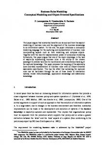
2.2. Language design There are many aspects to the design of a representation language, with many choices and decisions. This is not a new challenge and there is the notion of requirements engineering for language design. For instance, a recent paper by [47] proposes the vGREL approach for steps 1 and 2/3 of the overall language design pipeline proposed by Frank [16] and some of the 26 guidelines by [48] are applicable as well. We include here a summary of Frank’s waterfall model for domains-specific modelling languages [16], as shown in Figure 2, with the steps we focus on in this paper highlighted. We will step through these states in brief and with respect to applicability and related works on CDML design. For step 1, the scope is conceptual modelling languages, and the goals are at least model interoperability and, at least to some extent if feasible, runtime use of conceptual models for so-called ‘intelligent systems’ or ontology or conceptual-model driven information systems. Regarding steps 2 and 3, to the best of our knowledge, there is no requirements catalogue for CDMLs (step 2/3a), but several use cases (step 2/3b) have been reported in scientific literature; e.g., the termbanks for multiple languages requiring interoperability among ER and UML [49] and runtime integration of information about food in the Roman Empire with ORM [13]. Assigning priorities (step 2/3c) has been done for several languages, but mostly not explicitly. For instance, a priority may be the computational complexity of the problem of satisfiability checking, or scalability in the presence of large amounts of data (OWL 2 QL) or a scalable TBox (OWL 2 EL) [50], or to have as many language features as possible to cover all corner cases, such as the “narcissist” in medicine as the single example for local reflexivity in SROIQ [51]. Tables with alternative sets of conflicting requirements are available, such as the pros and cons of several logics for formalising conceptual models [17] and trade-offs for representing the KGEMT mereotopology in various logics [52]. For the CDMLs, it has yet to be decided how to assign priorities. One could survey industry [53], but it has been shown in at least one survey that modellers do not know the features well enough to be a reliable source [7]. Thus, existing works fall short on providing answers to steps 2 and 3. There are many papers describing a language specification (step 4), with the DLs the most popular by number of papers. Most of these papers do not have a metamodel, however. Regarding existing metamodels one may be able to reuse for the language specification: there are proposals especially in the conceptual modelling community, spanning theoretical accounts (e.g., [54, 49]), academic proof-of-concept implementations [55, 56, 57], and industry-level applications, such as in the Eclipse Modeling Framework1 . The UML diagrams in the OWL and UML standards [58, 1] are essentially metamodels as well. To enable a comparison between CDMLs, a unified metamodel is required, which reduces the choice to [55, 56, 49, 57]. The most recent metamodel [49] covers all the static structural components in unifying UML Class Diagrams, ER and EER, and ORM and ORM2 at the metamodel layer cf. the subsets in [55, 56, 57], and has both a glossary of elements and the constraints among them. It was developed in UML Class Diagram notation for communication [49] and formalised for precision [59]. Step 5 in the language design pipeline—design of a graphical notation—is straightforward for the current scope, for it will be mapped onto the graphical notation of UML Class diagrams, EER, and ORM2. The architecture of the tool (step 6) is concurrently being worked on [18], and only after that can one do step 7, which is thus outside of the current scope. While the 7-step waterfall process for domain-specific languages is generally applicable for logic-based CDML design as well, some ontological analysis during steps 2-4 should improve the outcome, to which we shall return in Section 3. The case for, and benefits of, using insights from ontology (analytic philosophy) to advance the modelling has been well-documented [60, 61], with many papers detailing improvements on precision of representing the information; e.g., deploying the UFO foundational ontology to improve the UML 2.0 metamodel [62] and examining the nature of relationships [63, 64], and more general philosophical assessments about conceptual models, such as regarding concepts [65] and 3D versus 4D conceptual models [66]. 1 https://www.eclipse.org/modeling/emf/
4
1a. Determine scope, benefits 1b. Long-term perspective 1c. Economics, feasibility
1. Clarification of Scope and Purpose 2. Analysis of Generic Requirements
3. Analysis of Specific Requirements
2/3a. Consult requirements catalogue 2/3b. Use scenarios 2/3c. Assign priorities
234.Ontological analysis of language features 4a. Specify syntax and semantics 4b. Define glossary 4c. Define metamodel
4. Language Specification
5a. Create sample diagrams 5b. Evaluate notation
5. Design of Graphical Notation 6. Development of Modelling Tool
7. Evaluation and Refinement
7a. Test cases 7b. Analyse against requirements 7c. Analyse effect of use against current practice
Figure 2: Language design, adapted from [16], where the focus of this paper is highlighted in bold and shared (green). The “234. Ontological analysis of language features” has been added to the 7-step process, which is elaborated on in Section 3.
Thus, current resources fall short especially on a clear requirements specification and priority-setting for CDMLs and on ontology-driven language design. We will contribute to filling these gaps in the following two sections. 2.3. Quantitative assessments on language feature use To the best of our knowledge, there are only two studies with a quantitative approach to CDML feature usage, which are on ORM diagrams used in industry and developed by one modeller [8] and on publicly available EER, UML, and ORM diagrams [9], whose ORM data are similar to those reported in [8]. The diagrams in the dataset of [9] were analysed using a unified metamodel [49], which facilitated cross-language comparisons and categorisation of entities in those languages into the harmonised terminology. A relevant selection of the terminology across the languages is included in Table 1. This metamodel’s top-type is Entity that has four immediate subclasses: Relationship with 11 subclasses, Role, Entity type with 9 subclasses, and Constraint that has 49 subclasses (i.e., across the three CDML families, there are 49 different types of constraint). In addition to the hierarchy, the entities have constraints declared among them to constrain their use; e.g., each relationship must have at least two roles and a disjoint object type constraint is only declared on class subsumptions. This metamodel was used to classify the entities of the diagrams in a set of 101 UML, (E)ER, and ORM/2 models that were publicly available2 . The average size of the diagram (vocabulary+subsumption) is about 50 entities/diagram, totalling to 8036 entities, of which 5191 (i.e., 64%) are entities that were classified in an entity (language feature) that is included in all three language families and 1108 (13.8%) in ones that are unique to a language family (e.g., UML’s aggregation) [9]. The obtained usage frequency for each entity, together with the design choices described in Section 3, sustain the logic profiles given in Section 4. 3. Design choices for logic-based profiles One could simply take the evidence of which CDML features are used most, and design a logic for it, or pick a logic one likes and make the best out of a logic-based reconstruction. This has resulted in an 2 the
models and analysis are available from http://www.meteck.org/swdsont.html, and not within the scope of this paper
5
Table 1: Terminology of the languages considered (relevant selection).
metamodel term term Relationship Role Entity type Object type
UML Class Diagram Association Association/ member end Classifier Class
EER Relationship Component of a relationship – Entity type
Attribute Value type
Attribute –
Attribute –
Data type
LiteralSpecification –
ORM/FBM
DL
Fact type Role
Role Role component
Object type Nonlexical object type/Entity type – Lexical object type/Value type Data type
– Concept – – Concrete domain
‘embarrassment of the riches’ in the plethora of logic-based reconstructions, and even more so when the formalisations are examined in detail. None is the same. The reason for this is that there are several design choices that each can result in a different logic of different computational complexity, using different reconstruction algorithms, with varying tooling support. Such choices have not been state upfront, but they have to be piecemeal reconstructed by anyone interested in logic foundations for conceptual models, because such decisions are sparsely discussed in the literature. This brings us to the “4” of the “234. Ontological analysis of language features” extension to [16]’s waterfall procedure for language development (recall Fig. 2 in Section 2.2). The step 4, “language specification”, concerns affordances and features of the logic, such as 1) the ability to represent the conceptualisation more or less precisely with more or less constraints3 , and 2) whether the language contributes to support, or even shape, the conceptualisation and one’s data analysis for the conceptual data model for an information system, or embeds certain philosophical assumptions and positions. Regarding the latter, we identified several decision points, which may not yet be an exhaustive list, but it is the first and most comprehensive list to date. They are as follows, and explained and discussed for CDMLs afterward: 1. Should the CDML be ‘truly conceptual’ irrespective of the design and implementation or also somewhat computational? That is, whether the language should be constrained to permit representation of only the what of the universe of discourse vs. not only what but also some how in the prospective system. The typical example is whether to include data types for attributes or not. 2. Are the roles that objects play fundamental components of relationships, i.e., should roles be elements of the language? 3. Will refinements of the kinds of general elements—that then have their own representation element— result in a different (better) conceptual model? For instance, (a) to have not just Relationship but also an extra element for, say, parthood; (b) to have not just Object type but also refinements thereof so as to indicate ontological distinctions between the kind of entities, such as between a rigid object type and the role it plays (e.g., Person vs Student, respectively); (c) if only binary relationships are allowed, the modeller may assume there are only binary relations in the world and reifications of n-aries vs the existence of n-aries (n ≥ 2) proper; 3 this
is distinct from subject domain coverage; to illustrate the difference: being able to represent, say, “has part =2 eyes” vs only “has part ≥ 1 eyes” concerns precision, whereas omitting information about the eyes concerns coverage.
6
(d) if only object types are allowed, the modeller may assume everything is a object in the world, though one may argue that ‘stuff’, such as Wine and Gold, is disjoint from object, and thus would have to be represented with a different element. 4. Does one have a 4-dimensionalist view on the world (space-time worms) and thus a language catering for that or are there only 3-dimensional objects with, perhaps, a temporal extension? 5. What must be named? The act of naming or labelling something amounts to identifying it and its relevance; conversely, if it is not named, perhaps it is redundant. Little is known about what effects the different decisions may have. The data analysis of [9] indicates that binaries vs n-aries (Item 3c) and just plain relationship vs also with aggregation (Item 3a) does indeed make a difference at least for UML vs (E)ER and ORM/2, in that UML class diagrams have disproportionately fewer n-aries and more aggregation associations than (E)ER and ORM/2. Regarding the former, it is known that n-aries in UML class diagrams are hard to read due to the look-across notation [67] and it uses a different visual element (diamond vs line), compared to (E)ER and ORM/2 that use the same notation for both binaries and n-aries; an investigation into the ‘syntactic sugar’ of the graphical elements is outside the current scope. The other options in Item 3 are philosophically interesting, but unambiguous industry requirements for them are sparse, except for ‘stuff’, because quantities of amounts of matter are essential to traceability of ingredients in, among others, the food production process and pills and vaccines production (e.g., [68, 69]). In this case, distinguishing between a countable object and a specific quantity of an amount of matter can more precisely relate, say, a specific, numbered, capsule of liquid medicine and the stock that the medicine came from, which, could aid investigations in case of contamination (e.g., the capsule was not cleaned properly vs a contaminated batch of liquid). To date, there is no CDML that includes this distinction other than one proposal for a UML stereotype by [70] and a set of relations for stuffs that could refine UML’s aggregation association [71]. The only proposal for refinements of Object Type (Item 3b) is OntoUML [72], which adds, among others, the stereotypes “role” and “phase”. More generally, the approach amounts to taking a foundational (top-level) ontology, such as UFO, GFO, or DOLCE, and to use some or all of those core categories to refine UML’s class or ER or ORM’s entity type. Choosing one foundational ontology may result in the situation where one’s diagrams or conceptual data modelling language ends up to be incompatible with one that adheres to another foundational ontology [73]. At the time of writing, it is not clear where or how exactly such refinements provide benefits, other than the typical example of preventing bad hierarchies that OntoClean [74] seeks to resolve. For instance, to not declare, say, Person as a subclass of Employee, because the former is a sortal and the latter is a role that the former plays for a limited duration. Instead, it either should be the other way around (Employee is a Person) or sideways (Employee is a role played by Person). Declaring each Object Type with their respective category and firing ontological rules, such as ‘a sortal cannot be subsumed by a role’, could then at detect automatically such quality issues in a diagram. From the viewpoint of logics and formalising it, something like this can be done with second-order logic, many-valued logics, or—easier on the logic, but ontologically unclean—have the elements in the diagrams be subsumed by the entities in a foundational ontology. Conceptual models and features for implementation decisions (Item 1). It is known theoretically at least that incorporating design and implementation decisions reduces potential for interoperability and integration with other systems. Two common examples are declaring data types of attributes (in UML and ORM/2) and entity type-specific attributes (in (E)ER and UML) vs value types that can be shared among entity types (ORM). ER and EER do not have data types, and its selection is pushed down to the design or implementation stage in the waterfall methodologies of database development; e.g., whether some attribute length should be recorded in integer or float is irrelevant in the data analysis stage. Value types, in contrast to attributes, can be reused by multiple entity types and can easily be reverted into entity types with minimal disruption to the diagram; e.g., a value type length means the same thing regardless whether it is used for the length of a Sofa or a Table for some furniture database. Of course, one can convert between 7
attributes and value types [17], but having a value type element in the language clearly enables extra analysis regarding common semantics in a model. Practically, for the design of a logic, the inclusion of value types entails that one has two types of object types: one that can relate only to other object types and one that relates to a data type. That, is not simply only one unary predicate in FOL or ‘concept’ in DL for everything, but another, disjoint one, that must relate to a data type specifically. The inclusion of attributes, or not, affects the language insofar as one wants to create, or already has, a type of relation that relates an object type to a data type. For instance, OWL’s Data Property. Ontological commitments for relationships (Item 2). Let us first illustrate the possible decisions that Item 2 asks for. Irrespective of the representation decision, there is some relationship, say, teach that holds between Professor and Course. With the ‘just predicates’ decision, there is assumed to be no teach relationship, or at least not represented as such, but there would be at least one predicate, teaches or taught by in which Professor and Course participate in that specific order or in reverse, respectively. With the ‘there are roles too’ decision, then Professor would play the role [lecturer] in the relationship teach and Course would play the role [subject] in the relationship teach; hence, role is an element in the language and deemed to be part of the so-called ‘fundamental furniture’ of the universe. This distinction between predicates-only and roles-too has been investigated by philosophers, and are there called standard view and positionalist, respectively. It has been argued that the positionalist commitment with roles (argument places) is ontologically a better way characterising relations than the standard view that enforces an artificial ordering of the elements in the relation and requires inverses4 , and it is also deemed better with respect to natural language interaction and expressing more types of constraints [75, 63, 20, 76]. This has been discussed at some length in [17] from a computational perspective, because the main issue is that the CDMLs are all positionalist, yet most logics use predicates with the standard view. To address this impasse, there are several options. One could commit to a logic-based reconstruction into a positionalist language, be this the DLR family that is used for a partial reconstruction of ER [39], UML class diagrams [10], and ORM [63], roles in the Z formalisation by [33], or one that is yet to be designed. One also could deny positionalism in some way and force it into a standard view logic. For instance, one could change the [lecturer] and [subject] roles into a teaches and/or a taught by predicate and declare them as inverses if both are included in the vocabulary, or pick one of the two and represent the other implicitly through taught by− or teaches− , respectively. Sampling decisions made in related works showed that, e.g., Pan and Liu [31] use a hybrid of both roles and predicates for ORM and its reading labels also may be ‘promoted’ to relationships [36], the original ORM formalisation was without roles in the language [22], and UML’s association ends are sometimes ignored as well (e.g., [32, 30]), but not always [10]. Exploring the conversion strategies brings one to the computational complexity of the logic. Mostly, adding inverses does not change the worst-case computational complexity of a language; e.g., ALCQ and ALCQI are both PSpace-complete [77], but a notable exception is the OWL 2 EL profile that does not have inverse object properties [50]. 3D vs. 4D (Item 4). The 3-dimensionalist approach takes objects to be 3-dimensional in space where the objects are wholly present at each point in time (i.e., they do not have temporal parts). Statements are true at the ‘present’, whilst being ignorant of the object in the past and future. If one wants to deal with time, it is added as an orthogonal dimension, as in, e.g., [78, 79]. The 4-dimensionalist approach, sometimes also called ‘fluents’, takes entities to exist in four dimensions, being space+time, they are not wholly present at each point in time, and do have temporal parts. Any statements can be about not only the present, but also the past and future (e.g. [80, 66]). A typical example in favour of 4D is to represent as accurately as possible the notion of a holding or supra-organisation [66], such as Alphabet and Nestl´e: these companies exist for some time and keep their identity all the while they acquire and sell other (subsidiary) companies. In a 3D-only representation, one would have a record of which companies they own now, but not whether they 4 and
anti-positionalist is argued to be better than positionalist [75, 76], but anti-positionalist is unpractical at this stage.
8
are the same ones as last year (unless temporal information is added in some way; e.g., through database snapshots or time stamps). The predominant choice of conceptual data modelling languages is 3D, although temporal extensions do exist especially for ER (e.g., [78, 79]). We could not find any evidence that can explain why this is the case. Naming things (Item 5). The act of naming things entails the interaction between natural language and ontology, and their interaction. We do not seek to discuss that millennia-old philosophical debate here, but one that is applied within the current context. Naming elements happens differently across the three CDML families. For instance, in UML class diagrams, the association ends must be named but the association does not necessarily have to be named, which typically is the other way around in (E)ER except for recursive relations, whereas ORM diagrams commonly only have reading labels of a relationship rather than naming either the roles or the relationship themselves. ORM thus clearly distinguishes between the conceptual layer and the natural language layer, but such workings are not taken into account explicitly in any of the formalisations, nor has it been explicitly decided whether it should be (other than in a model for roles in [20]). A systematic solution to this natural language ↔ ontology interaction has been investigated in the context of the Semantic Web, where the natural language dimension has its own extension on top of an OWL file [81], although it still relies on naming classes and object properties. What the three CDML families do have in common is that object types are always named, hence, at least part of that separation of ontology and lexicon might be of use in praxis. For designing a logic, this may not matter much, but it will have an effect on the algorithms to reconstruct the diagrams into a logical theory. Assessment of popular languages and their commitments. We assessed the relatively frequently occurring logics for formalising conceptual data models on whether it would be possible to choose a ‘best fit’ language. This comparison is included in Table 2. The first section of the table summarises the main design decisions discussed in the preceding paragraphs, whereas the second part takes into consideration non-ontological aspects with an eye on practicalities. Such practicalities include among others, scalability, tooling support, and whether it would be easily interoperable with other systems. Regarding the latter, we include the Distributed Ontology, Model, and Specification Language DOL that was recently standardised by the Object Management Group, which provides a metalanguage to link models in various logics, including up to second order logic5 . The first section in the table suggests DLRifd and FOL are good candidates for logic-based reconstructions of conceptual data models; the second section has more positive evaluations for DL-LiteA and OWL 2 DL. Put differently: neither of them is ideal, so one may as well design one’s own language for the best fit. 4. Logic-based profiles for conceptual data modelling languages We now proceed to define logics to characterise the minimalist semantics of each of the three families of CDMLs. This takes into account the ontological considerations discussed in the previous section as well as the evidence from [9] and the requirement to have a coverage of around 99% of the used entities and constraint. Because of afore-mentioned ontological reasons in favour of roles as well as that all three CDML families are positionalist, a Positionalist Core is defined despite its current lack of implementation support (Section 4.1.1). Afterward, a standard view Standard Core and language-specific profiles are defined in Sections 4.1.2-4.1.5. An overview of the upcoming definitions and algorithms is shown in Fig. 3. 4.1. Profiles Positionalism is the underlying commitment of the relational model and a database’s physical schema, as well as of the main CMDLs. It has been employed in Object-Role Modelling (ORM) and its precursor 5 http://www.omg.org/spec/DOL/
and http://dol-omg.org/.
9
Table 2: Popular logics for logic-based reconstructions of CDMLs assessed against a set of requirements; “–”: negative evaluation; “+”: positive; “NL-logic”: natural language interaction with the logic; “OT refinement”: whether the language permits second order or multi-value logics or can only do refinement of object types through subsumption.
DL-Lite A
DLRifd
– standard view
+ positionalist
– standard view
– standard view
– with datatypes
– with datatypes
– with datatypes
+ no datatypes
– no parthood primitive
– no parthood primitive
– no parthood primitive
– no parthood primitive
– no n-aries
+ with n-aries
– no n-aries
+ with n-aries
+ 3-dimensionalism
+ 3-dimensionalism
+ 3-dimensionalism
+ 3-dimensionalism
– OT refinement with subsumption
– OT refinement with subsumption
– OT refinement with subsumption
– OT refinement with subsumption
– no NL-logic separation
– no NL-logic separation
± partial NL-logic separation
– no NL-logic separation
– very few features; large fea-
+ little feature mismatch
± some feature mismatch,
+ little feature mismatch
OWL 2 DL Language features
ture mismatch
FOL
with overlapping sets
– logic-based reconstructions to complete
+ logic-based reconstructions exist
– logic-based reconstructions to complete
± logic-based tions exist
reconstruc-
Computation and implementability AC0
± EXPTIME-complete
± N2EXPTIME-complete
– undecidable
+ very scalable (TBox and ABox)
± somewhat (TBox)
± somewhat (TBox)
– not scalable
+ several reasoners
– no implementation
+ several reasoners
– few reasoners
+ linking with ontologies doable
– no interoperability
+ linking with ontologies doable
– no interoperability with widely used infrastructures
+ ‘integration’ with DOL
– no integration with DOL
+ ‘integration’ with DOL
+ ‘integration’ with DOL
+ modularity infrastructure
– modularity infrastructure
+ modularity infrastructure
– modularity infrastructure
+ PTIME (TBox); (ABox)
scalable
scalable
NIAM for the past 40 years [3], UML Class Diagram notation requires association ends as roles, and EntityRelationship (ER) Models have relationship components [17]. On the other hand, First Order Logic and most of its fragments, notably standard DLs [82], do not exhibit roles (DL role components) among its vocabulary. In order to be able to do reasoning, conceptual schemas written in these CMDLs are generally translated into a DL by removing roles, and thus losing the connection that exists when the same role is played by different concepts. For example, the lives at role may be played by a person in a house rent relationship by a person in a house mortgage relationship. This role name is relevant for querying lets say the real estate owners in the database, so it is relevant for the model’s intended meaning but the translation splits them into two different relationships. Therefore, we consider relevant to design a positionalist core profile that preserves roles as first class citizens among the DL vocabulary. In case reasoning over advanced modelling features is needed, it is possible to switch to the standard core profile with the cost of losing this connection. This translation is given in Algorithm 1. 4.1.1. Positionalist Core Profile In this section we define the logic that describes the positionalist core profile. Definition 1. Given a conceptual model in any of the analysed CDMLs, we construct a knowledge base in DC p by applying the rules: 1. we take the set all of object types A, binary relationships P , datatypes T and attributes a in the model as the basic elements in the knowledge base. 10
Figure 3: Sketch of the orchestration between the profiles and algorithms.
2. for each binary relationship P formed by object types A and B, we add to the knowledge base the assertions ≥ 1[1]P v A and ≥ 1[2]P v B. 3. for each attribute a of datatype T within an object type A, including the transformation of ORM’s Value Type following the rule given in [83], we add the assertion A v ∃a.T u ≤ 1a. 4. subsumption between two object types A and B is represented by the assertion A v B. 5. for each object type cardinality m..n in relationship P with respect to its i-th component A, we add the assertions A v ≤ n[i]P u ≥ m[i]P . 6. we add for each mandatory constraints of a concept A in a relationship P the axiom A v ≥ 1[1]P or A v ≥ 1[2]P depending on the position played by A in P . This is a special case of the previous one, with n = 1. 7. for each single identification in object type A with respect to an attribute a of datatype T we add the axiom id A a. This construction is linear in the number of elements in the original conceptual model, so reasoning complexity on the theory is the same as on the conceptual model. We restrict it to binary relationships only, because general n-ary relationships are rarely used in the whole set of analysed models. The (E)ER and ORM/2 models exhibit a somewhat higher incidence of n-aries, so they are included in the respective profiles; see below. Also, we allow only one such constraint for each component, multiple cardinality constraints over the same component in a relationship are used very rarely. DC p can be represented by the following DL syntax. Starting from atomic elements, we can construct binary relations R, arbitrary concepts C and axioms X according to the rules: C −→ > | A | ≤ k[i]R | ≥ k[i]R | ∀a.T | ∃a.T | ≤ 1 a | C u D R −→ >2 | P | (i : C) X −→ C v D | id C a where i = 1, 2 and 0 < k. For convenience of presentation, we generally use the numbers 1 and 2 to name the role places, but they can be any number or string and do not impose an order. Whenever necessary we note with U the set of all role names in the vocabulary, with from, to ∈ U fixed argument places for attributes such that [from] is the role played by the concept, and [to] the role played by the datatype. These names must be locally unique in each relationship/attribute. 11
Table 3: Semantics of DC p .
>I ⊆ ∆IC AI ⊆ >I I >2 = >I × > I P I ⊆ >I2 T I ⊆ ∆IT I a ⊆ >I × ∆IT (C u D)I = C I ∩ DI
(≤ k[i]R)I = {c ∈ ∆IC |#{(d1 , d2 ) ∈ RI .di = c} ≤ k} (≥ k[i]R)I = {c ∈ ∆IC |#{d1 , d2 ) ∈ RI .di = c} ≥ k} (∃a.T )I = {c ∈ ∆IC |∃b ∈ T I .(c, b) ∈ aI } (∀a.T )I = {c ∈ ∆IC |∀v ∈ ∆IT .(c, v) ∈ aI → v ∈ T I } (≤ 1 a)I = {c ∈ ∆IC |#{(c, v) ∈ aI } ≤ 1} (i : C)I = {(d1 , d2 ) ∈ >I2 |di ∈ C I }
Although this syntax represents all DC p knowledge bases, there are sets of formula following the syntactic rules that are not DC p knowledge bases since they are not result of any translation of a valid conceptual model. For example, the knowledge base {A v ∃a.T u ≥ 3a} is not a DC p knowledge base, because the syntactic production rules are only introduced to provide a proper semantic characterisation. Now we introduce the semantic characterisation Definition 2. An DC p interpretation I = (·IC , ·IT , ·I ) for a knowledge base in DC p consists of a set of objects ∆IC , a set of datatype values ∆IT , and a function ·I satisfying the constraints shown in Table 3. It is said that I satisfies the assertion C v D iff C I ⊆ DI ; and it satisfies the assertion id C a iff exists T such that C I ⊆ (∃a.T u ≤ 1a)I (mandatory 1) and for all v ∈ T I it holds that #{c|c ∈ C I ∧ (c, v) ∈ aI } ≤ 1 (inverse functional). In total, all the entities in the core profile sum up to 87.57% of the entities in all the analysed models, covering 91,88% of UML models, 73.29% of ORM models, and 94.64% of EE/EER models. Conversely, the following have been excluded from the core despite the feature overlap, due to their low incidence in the model set: Role (DL role component) and Relationship (DL role) Subsumption, and Completeness and Disjointness constraints. This means that it is not possible to express union and disjointness of concepts in a DC p knowledge base obtained by formalising a conceptual model. Clearly they can be expressed by combinations of the constructors in DC p , but this is not possible if we follow the previous construction rules. Since completeness and disjointness constraints are not present, reasoning in this core profile is quite simple. This logic DC p can be directly embedded into DLR (attributes are treated as binary relationships, and identification constraint over attributes can represented as in [41]) which gives EXPTIME worst case complexity for satisfiability and logical implication. A lower complexity would be expected due to the limitations in the expressivenes. For example, completeness and disjointness constraints are not present, and negation cannot be directly expressed. It is possible to code negation only with cardinality constraints [82, chapter 3], but then we need to reify each negated concept as a new idempotent role, which is not possible to get from the DC p rules. Another form of getting contradiction in this context is by setting several cardinality constraints on the same relationship participation, which is also disallowed in the rules. In any case, the main reasoning problems on the conceptual model are only class subsumption and class equivalence on the given set of axioms. In spite of all these limitations, no simpler positionalist DL has been introduced. In order to get lower complexity bounds we need to translate a DC p TBox to a standard (non-positionalist) logic, like DC s below. 4.1.2. Standard Core Profile Considering formalisation choices such as the positionalism of the relationships [63, 76] and whether to use inverses or qualified cardinality constraints, a standard core profile has been specified [17]. In case the original context is a positionalist language, a translation into a standard (role-less) language is required. Algorithm 1 (adapted from [17]) does this work in linear time in the number of elements of vocabulary. The main step involves recursive binary relations that generally do have their named relationship components vs ‘plain’ binaries that have only the relationship named. Definition 3. Given a conceptual model in any of the analysed CDMLs, we construct a knowledge based in DC s by applying algorithm 1 to its DC p knowledge base. 12
Algorithm 1 Positionalist Core to Standard Core P an atomic binary relationship; DP domain of P ; RP range of P if DP 6= RP then Rename P to two ‘directional’ readings, P e1 and P e2 Make P e1 and P e2 a DL relation (role) Type the relations with > v ∀P e1 .DP u ∀P e− 1 .RP Declare inverses with P e1 ≡ P e− 2 else if DP = RP then if i = 1, 2 is named then P ei ← i else P ei ← user-added label or auto generated label end if Make P ei a DL relation (role) Type one P ei , i.e., > v ∀P ei .DP u ∀P e− i .RP Declare inverses with P ei ≡ P e− 2 end if end if
>I ⊆ ∆IC AI ⊆ >I I >2 = >I × >I P I ⊆ >I2 T I ⊆ ∆IT I a ⊆ >I × ∆IT (C u D)I = C I ∩ DI
Table 4: Semantics of DC s .
(∀R.A)I = {c1 ∈ ∆IC |∀c2 .(c1 , c2 ) ∈ RI → c2 ∈ AI } (∃R.A)I = {c1 ∈ ∆IC |∃c2 .(c1 , c2 ) ∈ RI ∧ c2 ∈ AI } (≤ k R)I = {c1 ∈ ∆IC | #{c2 |(c1 , c2 ) ∈ RI } ≤ k} (≥ k R)I = {c1 ∈ ∆IC | #{c2 |(c1 , c2 ) ∈ RI } ≥ k} (∀a.T )I = {c ∈ ∆IC |∀v.(c, v) ∈ aI → v ∈ T I } (∃a.T )I = {c ∈ ∆IC |∃v.(c, v) ∈ aI ∧ v ∈ T I } (≤ 1 a)I = {c ∈ ∆IC | #{(c, v) ∈ aI }| ≤ 1} (R− )I = {(c2 , c1 ) ∈ ∆IC × ∆IC |(c1 , c2 ) ∈ RI }
Again, the algorithm is linear in the number of binary relationships in the knowledge base, not affecting complexity results when reasoning. Once this conversion step is done, the formalisation of the standard core profile is described as follows. It includes inverse relations to keep connected both relationships generated by reifying roles. Take atomic binary relations (P ), atomic concepts (A), and simple attributes (a) as the basic elements of the core profile language DC s , which allows us to construct binary relations and arbitrary concepts according to the following syntax: C −→ >1 | A | ∀R.A | ∃R.A | ≤ k R | ≥ k R | ∀a.T | ∃a.T | ≤ 1 a.T | C u D R −→ >2 | P | P − X −→ C v D | id C a Definition 4. A DC s interpretation for a knowledge base in DC s is given by I = (·IC , ·IT , ·I ), with ∆Ic the domain of interpretation for concepts, ∆IT the domain of datatype values, and the interpretation function ·I satisfying the conditions in Table 4. I satisfies an axiom X as in DC p . From the perspective of reasoning over DC s , this is rather simple and little can be deduced: negation cannot be directly expressed here either, as discussed for DC p . This leaves the main reasoning problem of class subsumption and class equivalence here as well. At most the DL ALN I (called PL1 in [84]) is expressive enough to represent this profile, since we only need >, u, inverse roles and cardinality constraints; PL1 has polynomial subsumption, but its data complexity is unknown. That said, using a similar encoding 13
(HN )
of conceptual models as given in Section 4.1.1, the language can be reduced further to DL-Litecore which is NLOGSPACE with some restrictions on the interaction between role inclusions and number restrictions, and the Unique name Assumption (UNA). Observe that adding class disjointness to this language would (HN ) result in a high jump in the complexity, since then the reduction would be to DL-Litebool which is NP-hard [85]. 4.1.3. UML Class diagram Profile The profile for UML Class Diagrams strictly extends DC s . It was presented extensively in [17]. Definition 5. A knowledge base in DC U M L from a given conceptual model in UML is obtained by adding to its DC s knowledge base the following formulas and axioms: 1. for each attribute cardinality m..n in an attribute a of datatype T within an object type A we add the assertion A v ≤ n a.T u ≥ m a.T . 2. for each binary relationship subsumption between relationships R and S we add the axiom R v S. The syntax is as in DC s , with the additions highlighted in bold face for easy comparison: C −→ > | A | ∀R.A | ∃R.A | ≤ k R | ≥ k R | ∀a.T | ∃a.T C −→≤ k a.T | ≥ k a.T | C u D R −→ >2 | P | P − X −→ C v D | R v S | id C a With this profile, we cover 99.44% of all the elements in the UML models of the test set. Absence of rarely used UML-specific modelling elements, such as the qualified association (relationship), completeness and disjointness among subclasses do indeed does limit the formal meaning of their models. On the positive side from a computational viewpoint, however, is that adding them to the language bumps up the complexity of reasoning over the models (to EXPTIME-hardness [10]); or: the advantage of their rare use is that reasoning over such limited diagrams has just becomes much more efficient than previously assumed to be needed. Definition 6. A DC U M L interpretation for a DC U M L knowledge base is a DC s interpretation I that also satisfies R v S if and only if RI ⊆ S I , with (≤ k a.T )I = {c ∈ ∆IC | #{a ∈ T I |(c, a) ∈ aI } ≤ k} and (≥ k a.T )I = {c ∈ ∆IC | #{a ∈ T I |(c, a) ∈ aI } ≥ k}. Compared to DC s , role hierarchies have to be added to the ALN I logic of the Core Profile, which yields the logic ALN HI. To the best of our knowledge, this language has not been studied yet. If we adjust it a little by assuming unique names and some, from the conceptual modelling point of view, reasonable restrictions on the interaction between role inclusions and cardinality constraints, then the UML profile 0 can be represented in the known DL-LiteHN core , which is NLOGSPACE for subsumption and AC for data complexity [85]. Also, if one wants to add attribute value constraints to this profile then reasoning over concrete domains is necessary. The interaction of inverse roles and concrete domains is known to be highly intractable, just adding them to ALC gives NEXPTIME-hard concept satisfiability [86]. 4.1.4. ER and EER Profile The profile for ER and EER Diagrams also extends DC s . Definition 7. A knowledge base in DC EER from a given conceptual model in EER is obtained by adding to its its DC s knowledge base the following formulas and axioms: 1. we include atomic ternary relationships in the basic vocabulary. 2. for each attribute cardinality m..n in an attribute a of datatype T within an object type A we add the assertion A v ≤ n a.T u ≥ m a.T . 14
3. for each weak identification of object type A through relationship P in which it participates as the i3 -th component, the we add the assertion fd R i1 , i2 → i3 , such that 1 ≤ i, i1 , i2 ≤ 3 and are all different. 4. associative object type are formalised by the reification of the association as a new DL concept with two binary relationships. 5. multiattribute identification is formalised as a new composite attribute with single identification. This profile was presented extensively in [17] and is here recast in shorthand DL notation. The syntax is as in DC s , with the additions highlighted in bold face for easy comparison: C −→ > | A | ∀R.A | ∃R.A | ≤ k R | ≥ k R | ∀a.T | ∃a.T C −→≤ k a.T | ≥ k a.T | C u D R −→ >n | P | P − X −→ C v D | id C a | fd R i1 , i2 → i3 where n = 2, 3 and all ij = 1, 2, 3 and different. Definition 8. An interpretation I satisfies a knowledge base in DC EER is it is a DC s interpretation, and satisfies fd R i1 , i2 → i3 iff for all r, s ∈ RI it holds that if [i1 ]r = [i1 ]s and [i2 ]r = [i2 ]s then [i3 ]r = [i3 ]s, , with (≤ k a.T )I = {c ∈ ∆IC | #{a ∈ T I |(c, a) ∈ aI } ≤ k} and (≥ k a.T )I = {c ∈ ∆IC | #{a ∈ T I |(c, a) ∈ aI } ≥ k}. This profile covers relative frequent EER modelling entities such as composite and multivalued attributes, weak object types and weak identification, ternary relationships, associated objet types and multiattribute identification in addition to those of the standard core profile. This profile can capture 99.06% of all the elements in the set of (E)ER models. Multivalued attributes can be represented with attribute cardinality constraints, and composite attributes with the inclusion of the union datatype derivation operator. Each object type (entity type) in (E)ER is assumed by default to have at least one identification constraint. In order to represent external identification (weak object types), we can use functionality constraints on roles as in DLRifd [41] and its close relative DLR+ [87] or in CF D [88]. Ternary relationships are explicitly added to the profile. If we want to preserve the identity of these relationships in the DL semantics, then we need to restrict to logics in the DLR family. Otherwise, it is possible to convert ternaries into concepts by reification, as described in Algorithm 2, using three traditional DL roles and therefore allowing the translation into logics such as CF D. Since associative object types do not impose new static constraints on the models, they are formalised by reification of the association as a new DL concept with two binary relationships. Finally, multiattribute identification can be represented as a new composite attribute with single identification. This profile presents an interesting challenge regarding existing languages. The only DL language family that has arbitrary n-aries and the advanced identification constraints needed for the weak entity types is the positionalist DLRifd . However, DLRifd also offers DL role components that are not strictly needed for (E)ER, so one could pursue a binary or n-ary DL without DL role components but with identification constraints, the latter being needed of itself and for reification of a n-ary into a binary (Algorithm 2). The CF D family of languages may seem more suitable, then. Using Algorithm 2’s translation, and since we do not have covering constraints in the profile, we can represent the (E)ER Profile in the description logic DL-LiteN core [85] which has complexity NLOGSPACE for the satisfiability problem. This low complexity is in no small part thanks to its UNA, whereas most logics operate under no unique name assumption. A similar result is found in [27] for ERref , but it excludes composite attributes and weak object types. 4.1.5. ORM and ORM2 Profile Unlike for the ER and EER profile, there is no good way to avoid the ORM roles (DL role components), as they are used for several constraints that have to be included. Therefore, to realise this profile, we must transform the ORM positionalist commitment into a standard view, as we did in Algorithm 1. This 15
Algorithm 2 Equivalence-preserving n-ary into a binary conversion vDP : domain of P ; RP range of P ; n set of P -components Reify P into P 0 v > for all i, 3 ≥ i ≥ n do Rei ← user-added label or auto generated label Make Rei a DL role, Type Rei as > v ∀Rei .P 0 u ∀Re− i .RP , where RP is the player ((E)ER entity type) in n Add P 0 v ∃Rei .> and P 0 v ≤ 1 Rei .> end for Add external identifier > v ≤ 1 (ti Rei )− .P 0
is motivated by the observation that typically fact type readings are provided, not user-named ORM role names, and only 9.5% of all ORM roles in the 33 ORM diagrams in our dataset had a user-defined name, with a median of 0. We process the fact type (relationship P ) readings and ignore the role names following Algorithm 3. DLR’s relationship is typed, w.l.o.g. as binary and in DLR-notation, as P v [rc ]C u [rd ]D, with rc and rd variables for the ORM role names and C and D the participating object types. Let read1 and read2 be the fact type readings, then use read1 to name DL role Re1 and read2 to name DL role Re2 , and type P as > v ∀Re1 .C u ∀Re2 .D. This turns, e.g., a disjoint constraints between ORM roles rc of relationship P and sc of S into Re1 v ¬Se1 and Se1 v ¬Re1 . Algorithm 3 ORM/2 to standard view and common core. P an atomic relationship if P is binary then Take fact type readings F if there is only one fact type reading then Re1 ← F Type Re1 with domain and range Create Re2 Declare Re1 and Re2 inverses else Assign one reading to Re1 and the other to Re2 Type Re1 with domain and range accordingly Declare Re1 and Re2 inverses end if else P is n-ary with n > 2 Reify P into P 0 v >, like in Algorithm 2, with for the n binaries using the fact type readings as above end if The profile for ORM/2 Diagrams was presented in [17], and a more detailed version including a textbased mapping as a restricted “ORM2cfd ” was developed in [19] using CF DI ∀− as underlying logic, yet nc that could cover only just over 96% of the elements in the set of ORM models, whereas this one reaches 98.69% coverage. Definition 9. A knowledge base in DC ORM from a given conceptual model in ORM2 is obtained by adding to its DC s knowledge base the following formulas and axioms: 1. each n-ary relationship is reified as in Algorithm 3. 2. each unary role is formalised as a boolean attribute. 3. each subsumption between roles R, S is represented by the formula R v S. 16
4. each subsumption between relationships is represented as a subsumption between the reified concepts. 5. each disjoint constraint between roles R and S is formalised as two inclusion axioms for roles: R v ¬S and S v ¬R. 6. each nested object type is represented by the reified concept of the relationship. 7. each value constraint is represented by a new datatype that constraint. 8. each disjunctive mandatory constraint for object type A in roles Ri is formalised as the inclusion axiom A v ti ∃Ri . 9. each internal uniqueness constraint for roles Ri , 1 ≤ i ≤ n over relationship objectified with object type A is represented by the axiom id A 1R1 , . . . , 1Rn 10. each external uniqueness constraint between roles Ri , 1 < i ≤ n not belonging to the same relationship can be formalised with the axiom id A 1R1 , . . . , 1Rn , where A is the connected object type between all the Ri , if it exists, or otherwise a new object type representing the reification of a new n-ary relationship between the participating roles. 11. each external identification is represented as the previous one, with the exception that we are now sure such A exists. (i.e., the mandatoryness is added cf. simple uniqueness). This slightly more comprehensive one is here recast in shorthand DL notation, with the additions highlighted in bold face for easy comparison: C −→ >1 | A | ∀R.A | ∃R.A | ≤ k R | ≥ k R | ∀a.T | ∃a.T | ≤ 1 a.T C −→ C u D | C t D R −→ >2 | P | P − | ¬R X −→ C v D | R v S | id C a | id C R1 . . . Rn
Definition 10. A DC ORM interpretation for a DC ORM knowledge base is a DC s interpretation I with the constraints that (C t D)I = C I ∪ DI , and (¬R)I = >I2 \RI . I satisfies the assertion R v S iff (R v S)I = RI ⊆ S I , and the assertion id C R1 . . . Rn iff C I ⊆ ∩i (∃Ri u ≤ 1Ri )I and for all objects d1 , . . . , dn ∈ T I it holds that #{c|c ∈ C I ∧ (c, di ) ∈ RiI , 1 ≤ i ≤ n} ≤ 1. We decided not to include any ring constraint in this profile. Although the irreflexivity constraint counts for almost half of all appearances of ring constraints, its participation is still too low to be relevant. The semantics, compared to DC s , is, like with the UML profile, extended in the interpretation for relationship subsumption. It also needs to be extended for the internal uniqueness, with the identification axioms for relationships. Concerning complexity of the ORM/2 Profile, this is not clear either. The EXPTIMEcomplete DLRifd is the easiest fit, but contains more than is strictly needed: neither concept disjointness and union are needed (but only among roles), nor its fd for complex functional dependencies. The PTIME CF DI ∀− nc [89] may be a better candidate if we admit a similar translation as the one given in Algorithm 2, but giving up arbitrary number restrictions and disjunctive mandatory on ORM roles. 4.2. Example application of the construction rules Let us now return to the claim in the introduction about the sample UML Class Diagram in Fig. 1: that it has a logical underpinning in DC s and therewith also has grounded equivalents in EER and ORM notation. The equivalents in EER and ORM are shown in Fig. 4. The first step is to note that the DC s reconstruction is obtained from DC p + Algorithm 1 (by Definition 3). By the DC p rules from Definition 1, we obtain the set of object types (fltr) {Person, Affiliation, ..., Publisher} and of data types {Name, ..., VAT reg no}. For the relationships, we need to use Algorithm 1, which we 17
illustrate here for the association between Person and Affiliation: 1) bump up the association end names, has member and has, to DL roles; 2) type the relationships with: > v ∀has member.Affiliation u ∀has member− .Person > v ∀has.Person u ∀has− .Affiliation and 3) declare inverses, has member ≡ has− . After doing this for each association in the diagram, we continue with step 3 of Definition 1, being the attributes. For instance, the Person’s Name we obtain the axiom Person v ∃Name.String u ≤ 1 name and likewise for the other attributes. Step 4 takes care of the subsumptions; among others Popular science book v Book is added to the DC s knowledge base. Then cardinalities are processed in steps 5 and 6 (noting the algorithmic conversion from positionalist to standard view applies in this step), so that, for the membership association illustrated above, the following axioms are added to the knowledge base: Affiliation v ≥ 1 has member (mandatory participation) whereas for, say, the scientist, it will be Scientist v ≤ 3 has. Finally, any identifiers are processed, such as ISBN for Book, generating the addition of the id Book ISBN to the DC s knowledge base. The process for the EER diagram is the same except that the name of the relationship can be used directly cf. bumping up the role names to relationship names. The reconstruction into ORM has two permutations cf. the UML one, which are covered by step 3 in Definition 1, being the conversion algorithm from ORM’s value types to attributes as described in [83], and it passes through the second else statement of Algorithm 1 cf. the first if statement that we used for UML when going from positionalist to standard view. Diagram construction rules, i.e., going in the direction from the logic-based profile to a graphical notation, can follow the same process in reverse. This can be achieved automatically, except where labels have to be generated. For instance, if one were to have a scenario on an interoperability tool of “UML diagram → DC s → ORM diagram” and one wants to have the fact type readings, they will have to be added, which a user could write herself or it could be generated by one of the extant realisation engines for the controlled natural language6 , similar to OWL verbalisation [90] or SimpleNLG for natural language generation [91]. 5. Discussion The methodological approach proposed is expected to be of use for similar research to inform better the language design process and elucidate ontological commitments that are otherwise mostly hidden. The five profiles form an orchestrated network of compatible logics, which serve as the logic-based reconstructions of fragments of the three main CDMLs that include their most used features. In the remainder of the section, we discuss language design, computational complexity, and look ahead at applicability. Language design. To the best of our knowledge, there is no ‘cookbook process’ for logic or conceptual data modelling language design. Frank’s waterfall process [16] provided useful initial guidance for a methodological approach. In our experience in designing the profiles, we deemed our proposed extension with “Ontological analysis of language features” necessary for the conceptual modelling and knowledge representation languages setting cf. Frank’s DSLs. An alternative option we considered beforehand was [48]’s list of 26 guidelines, but they are too specific to DSLs to be amenable to CDML design, such as the DSL’s distinction between abstract and concrete syntax and their corresponding guidelines. Zooming into that extra “Ontological analysis of language features” step, we had identified five decision points for language design with respect to ontology and several practical factors that are listed in Table 2 in Section 3. To the best of our knowledge, it is the first attempt to scope this component of language/logic 6 It
would have rules that render, e.g., a has member into ... has member ... and a has member− into ... member of ...
18
Name
0..n
Person
1..n
member
0..n
0..n
member
Scientist
0..n
affiliation
1..n
writing
editing
1..n
>=2
Address
Copy editor
0..n
reviewing
Country