Mathware & Soft Computing 14 (2007) 103-123
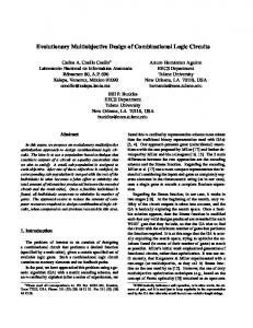
Evolutionary Design of Digital Circuits Using Improved Multi Expression Programming (IMEP) F.Z. Hadjam1 , C. Moraga2 and M.K. Rahmouni3 Dept. Comp. Science, University of Djillali Liabes, Sidi Bel Abbes, Algeria. 2 European Centre for Soft Computing, 33600 Mieres, Spain. 2 FB Informatik, Universit¨at Dortmund, 44221 Dortmund, Deutschland. 3 Dept. Comp. Science, University Essenia, Oran, Algeria
[email protected],
[email protected],
[email protected] 1
Abstract Evolutionary Electronics is a research area which involves application of Evolutionary computation in the domain of electronics. It is seen as a quite promising alternative to overcome some drawbacks of conventional design. In this paper we propose a methodology based on an Improved Multi Expression Programming (IMEP) to automate the design of combinational logic circuits in which we aim to reach the functionality and to minimize the total number of used gates. MEP is a genetic Programming variant that uses linear chromosomes for solution encoding. A unique MEP feature is its ability of encoding multiples solutions of a problem in a single chromosome. These solutions are handled in the same time complexity as other techniques that encode a single solution in a chromosome. This paper presents the main idea of an improved version of the MEP method, and shows positive preliminary experimental results. Keywords: Evolutionary Computation, Genetic Programming, Multi Expression Programming, combinational circuits, computational effort.
1
Introduction
Automatic methods of digital circuit design are desirable, as a skilled human designer’s time is often expensive. Some parts of the design process, such as finding the optimal set of component specifications to fulfill certain criteria, are often considered tedious, as they do not fully use a designer’s skill. Considering the increasing interest, research and application of evolutionary computation successfully used to solve search and optimization problems (particularly in cases when no efficient algorithms are known), a new field emerges: 103
104
F.Z. Hadjam, C. Moraga & K.M. Rahmouni
Evolutionary Electronics (EE). This new field is now seen as holding good chances for overcoming the drawbacks of conventional design techniques. EE considers the concept for automatic design of electronic systems, employing search algorithms to develop good designs. The idea of electronic circuit design as a search task is summarized as follows [16]: Imagine a design space where each point in that space represents the design of an electronic circuit. All possible electronics circuits are there, given the component types available to the electronics engineer and the technological restrictions on how many components there can be and how they can interact. In this metaphor, we loosely visualize the circuits to be arranged in the design space so that similar circuits are close to each other. The idea of using Evolutionary Algorithms is not only to optimize digital chips layout, but also to accomplish the whole process of circuit design, including designing the circuit topology from scratches. Recent research has begun to show that it is possible to design such circuits in a radically different way. One regards the problem of implementing the circuit as being equivalent to designing a black box with inputs and outputs. The content of the box is encoded into a chromosome and subject to the process of evolutionary algorithms. In this technique, the fitness of a particular chromosome is measured as the degree to which the black box outputs behave in the desired way. Sushil and Rawlins [6] applied GAs to the combinational circuits design problem while John Koza [5] adopted genetic programming. Coello, Christiansen and Aguire [2] presented a computer program that automatically generates high quality circuit designs. Miller and Thomson [7] et [8] two of the pioneers in the field the evolvable digital circuits, used a special technique called Cartesian Genetic Programming (CGP). The results [9] show that CGP was able to evolve some digital circuits better than those designed by human experts. The rest of the paper is structured as follows. The involved problem is defined in section 2. In section 3 we describe Multi-Expression Programming (MEP). Section 4 shows how MEP is improved. Our experimental details, results and comparisons with other methods are presented in section 5. Section 6 gives conclusions and some suggestions for further work.
2
Problem Statement
Design is first the process of deriving, from an Input/Output behavior specification, a structure (a combination of logic gates) that is functional (all combinations of the truth table are satisfied). Furthermore, we want this design to be optimum in terms of a certain set of specified constraints (e.g., the number of gates used, the depth of the produced circuit or expected power consumption).
Evolutionary Design of Digital Circuits Using IMEP
105
Genetic programming is an extension of John Holland’s genetic algorithm (1975) in which the population consists of computer programs of varying sizes and shapes. Genetic programming ordinarily evolves computer programs that are represented as rooted, point-labeled trees with ordered branches. Multi Expression Programming (MEP) [11], [12] is a Genetic Programming (GP) variant that uses linear chromosomes for solution encoding. A unique MEP feature is its ability of encoding multiple solutions of a problem in a single chromosome. These solutions are handled within the same time complexity as other techniques that encode a single solution in a chromosome. In our work, we are using an Improved Multi Expression Programming (IMEP) for evolving digital circuits. MEP uses linear chromosomes of fixed length. It has been documented [11] that MEP performs significantly better than other competitor techniques (such as Genetic Programming, Cartesian Genetic Programming, Gene Expression Programming and Grammatical Evolution) for some well-known problems such as symbolic regression and even-parity. In this paper, we focus only on combinational logic circuits, which contain no memory elements and no feedback paths. However, the approach proposed is general enough as to allow its generalization to more complex circuits.
3
Multi Expression Programming (MEP)
The Multi Expression Programming (MEP) technique is described in this section: The standard MEP algorithm [10] uses a steady state as its underlying mechanism. The MEP algorithm starts by creating a random population of individuals. The following steps are repeated until a stop condition is reached. Two parents are selected using a selection procedure. The parents are recombined in order to obtain two offsprings. The offsprings are considered for mutation. The best offspring replaces the worst individual in the current population if the offspring is better than the worst individual. The algorithm returns as its answer the best expression evolved along a fixed number of generations. MEP genes are represented by substrings of a variable length. The number of genes per chromosome is constant. This number defines the length of the chromosome. Each gene encodes a terminal or a function symbol. A gene encoding a function includes pointers towards the function arguments. Function arguments always have indices of lower values than the position of that function in the chromosome which ensures that no cycle arises while the chromosome is decoded. According to the proposed representation scheme [13], [10] the first symbol of the chromosome must be a terminal symbol. In this way only syntactically correct programs (MEP individuals) are obtained. Offsprings obtained by crossover and mutation are always syntactically correct. Thus, no extra processing for repairing newly obtained individuals is needed (see Section 4.4).
106
F.Z. Hadjam, C. Moraga & K.M. Rahmouni
Let us consider the following representation example in which, we will use the following sets: • Function set : F = AND, OR, XOR • Terminal set : T = a, b, c An example of chromosome using the sets F and T is given below (the labels shown in the example do not belong to the chromosome): 1: a 2: b 3: AND 1, 2 4: c 5: OR 1, 2 6: XOR 3, 5 7: AND 4, 6 The phenotype’s transcription of the example given above is shown by figure 1.
Figure 1: Expressions encoded by a MEP chromosome represented as trees
Evolutionary Design of Digital Circuits Using IMEP
4
107
IMEP for evolving digital circuits
In this section, we show how the MEP method is improved. The new representation is based on rearranging the nodes: we keep all terminals in the first positions (genes) and no other genes containing terminals are allowed in the rest of the chromosome. We have done this change to improve efficiency (see below, mutation). For example: (See table 1)
Old representation 1: a 0 0 2: b 0 0 3: AND 1 2 4: c 0 0 5: OR 1 2 6: XOR 3 5 7: AND 4 6
New representation 1: a 0 0 2: b 0 0 3: c 0 0 4: AND 1 2 5: OR 1 2 6: XOR 4 5 7: AND 3 6
Table 1: The new representation versus the old representation.
4.1
MEP Algorithm
S1. Randomly create the initial population P(0) S2. for t = 1 to Max Generations do S3. for k = 1 to abs(P(t) / 2 do S4. p1 = Select(P(t)); // select one individual from the current population S5. p2 = Select(P(t)); // select the second individual S6. Crossover (p1, p2, o1, o2); // crossover parents p1 and p2 // offsprings o1 and o2 are obtained S7. Mutation (o1); // mutate the offspring o1 S8. Mutation (o2); // mutate the offspring o2 S9. Select best the individual from o1,o2, the worst individual based on the fitness; S10. endfor S11. endfor
4.2
Improved MEP Algorithm
S1. Randomly create the initial population P(0) // keeping all terminals in the first positions. S2. for t = 1 to Max Generations do S3. for k = 1 to abs(P(t) / 2)do S4. p1 = Select(P(t)); // select one individual from the current population S5. p2 = Select(P(t)); // select the second individual S6. Crossover (p1, p2, o1, o2); // crossover the parents p1 and p2 // the offspring
108
F.Z. Hadjam, C. Moraga & K.M. Rahmouni
o1 and o2 are obtained S7. Mutation (o1); // mutate the offspring o1 S8. Mutation (o2); // mutate the offspring o2 S9. Select best 2 individuals from P1, P2, O1,O2 based on the fitness S10. Endfor S11. Mutate a copy of the Best Individual S12. Replace randomly an individual with the the mutated copy // avoid to lose the fittest S13. Mutation(Worst Individual) S14. Replace the worst individual with the worst mutated S15. Endfor Notice that S13 and S14 were added to the algorithm because some times the worst individual may contain good genes to be exploited, so by mutating this individual its fitness may improve and therefore it will have better chances to be selected.
4.3
Fitness computation
Each circuit has one or more inputs (denoted by NI) and one or more outputs (denoted by NO). When multiple genes are required as outputs we have to select those output genes which minimize the difference between the obtained results and the expected output. Each of the IMEP chromosome expressions is considered as being a potential solution of the problem. Partial results are computed by Dynamic Programming [1]. A terminal symbol specifies a simple expression (a variable: circuit input). A function symbol specifies a complex expression obtained by connecting the operands specified by the argument positions with the current function symbol. The fitness of each sub-expression (gene) is calculated by computing this sub-expression for each case (truth table input combinations) and then comparing with the corresponding target value (truth table outputs): the fitness value is given by the number of not matching values. The chromosome fitness is defined as the fitness of the best expression(s) encoded by that chromosome. Fitness = 0 means that 100% of target values match with the values given by this (these) sub-expression(s). The quality of the gene for a given output is given by (eq 1) in [10]. f (Ei , q) =
n X
(Oi,k − Wk,q )
(1)
k=1
Where Oi,k is the computed value for the gene i (Expression i) and for the combination k and Wk,q is the target value for the combination k and the output q. The minimized fitness for a given output is given by (eq 2) in [10].
Evolutionary Design of Digital Circuits Using IMEP
Parent P1 0: x0 0 0 1: x1 0 0 2: x2 0 0 3: xor 0 0 4: and 3 2 5: and 1 4 6: and 1 5 7: xor 4 6 8: and not 4 0 9: xor 4 7 10: and 4 8 11: and not 5 9
Parent P2 0: x0 0 0 1: x1 0 0 2: x2 0 0 3: and not 2 0 4: and 1 3 5: xor 4 2 6: and not 2 5 7: xor 6 0 8: xor 7 4 9: and not 7 2 10: and not 5 5 11: and 10 5
Offspring O1 0: x0 0 0 1: x1 0 0 2: x2 0 0 3: and not 2 0 4: and 3 2 5: xor 4 2 6: and 1 5 7: xor 4 6 8: and not 4 0 9: and not 7 2 10: and not 5 5 11: and not 5 9
109
Offspring O2 0: x0 0 0 1: x1 0 0 2: x2 0 0 3: xor 0 0 4: and 1 3 5: and 1 4 6: and not 2 5 7: xor 6 0 8: xor 7 4 9: xor 4 7 10: and 4 8 11: and 10 5
Table 2: Multi-cut crossover operation (exchange points 3, 5, 9 and 10).
f (O) =
min
i1 ,i2 ,···,iN O
NO X
f (Ei,q , q)
(2)
q=1
In our case, the minimized fitness is chosen with respect to the minimum number of not matching values (Eq 2), then to the max number of correct outputs in the same chromosome and finally to the minimum of the total number of gates (circuit devices). The observation of the correct outputs in the same chromosome covers the case when during evolution a chromosome might possibly lead to a circuit giving some correct outputs, but at permuted positions.
4.4
The evolution operators
The evolution operators used within IMEP algorithm are Selection, Crossover and Mutation. As explained earlier (Section 3), they preserve the chromosome structure thus, all offspring are syntactically correct expressions. Selection: we use the Tournament with variable size. The size is dependent on the population size. The most used value is 2 . Crossover: two parents are selected and recombined to produce offsprings. In our experiments, we have considered two kinds of crossover: One cut crossover and multi-cut crossover. Cut points are chosen randomly. Example: Let us consider the two parents P1 and P2 given below. If the multi-cut crossover is used with the selected exchange points 3, 5, 9 and 10 then two offspring O1 et O2 are obtained (See table 2).
110
F.Z. Hadjam, C. Moraga & K.M. Rahmouni
Parent P1 0: x0 0 0 1: x1 0 0 2: x2 0 0 3: xor 0 0 4: and 3 2 5: and 1 4 6: and 1 5 7: xor 4 6 8: and not 4 0 9: xor 4 7 10: and 4 8 11: and not 5 9
Parent P2 0: x0 0 0 1: x1 0 0 2: x2 0 0 3: and not 2 0 4: and 1 3 5: xor 4 2 6: and not 2 5 7: xor 6 0 8: xor 7 4 9: and not 7 2 10: and not 5 5 11: and 10 5
Offspring O1 0: x0 0 0 1: x1 0 0 2: x2 0 0 3: xor 0 0 4: and 3 2 5: and 1 4 6: and 1 5 7: xor 6 0 8: xor 7 4 9: and not 7 2 10: and not 5 5 11: and 10 5
Offspring O2 0: x0 0 0 1: x1 0 0 2: x2 0 0 3: and not 2 0 4: and 1 3 5: xor 4 2 6: and not 2 5 7: xor 4 6 8: and not 4 0 9: xor 4 7 10: and 4 8 11: and not 5 9
Table 3: One-cut crossover operation (exchange points 6).
If one cut point crossover is used (for instance at 6) then two offsprings O3 and O4 are obtained (See table 3). Mutation: According to the new representation, the mutation process has been modified. The first genes representing the problem variables are immune against mutation. The function symbols can be mutated only into other function symbols and the links (pointing to the function arguments) can also be mutated into other links, however satisfying the constraint that function arguments always have indices of lower values than the position of that function in the chromosome. See table 4. The original method [10] describes the mutation as follows: each symbol (terminal, function or link) in the chromosome may be target of the mutation operator (a terminal may become a function and function may become a terminal). The first gene of the chromosome must always encode a terminal symbol.
5
Numerical experiments
In this section, numerical experiments with Improved MEP for evolving digital circuits, are performed. For this purpose several well-known test problems [9] are used. To assess the performance of the algorithms, we consider two statistics : the Success Rate and the Computational Effort: • Success Rate = Number of successful runs / the total number of runs • Computational Effort: in [5] Koza describes a method to compare the results of different evolutionary methods. The so called Computational Effort is calculated as the number of fitness evaluations needed to find a solution of a problem with a probability of success z of at least z = 99%. We have
Evolutionary Design of Digital Circuits Using IMEP
Chromosome C 0: x0 0 0 1: x1 0 0 2: x2 0 0 3: xor 0 1 4: and not 2 3 5: and 0 4 6: and 5 2 7: xor 4 6 8: and not 5 7 9: xor 4 5 10: and 8 9 11: and not 10 7
111
Offspring O 0: x0 0 0 1: x1 0 0 2: x2 0 0 3: and 0 1 4: and not 2 3 5: xor 0 2 6: and 5 2 7: xor 4 6 8: and 4 3 9: xor 4 5 10: and 8 9 11: and not 10 7
Table 4: Mutation in genes 3,5 and 8.
to use relative frequencies instead of probabilities for finding the solution after a certain number of fitness evaluations. One first calculates P(M,i), the probability of success by generation i using a population of size M. For each generation i this is simply the total number of runs that succeeded on or before the ith generation, divided by the total number of runs conducted. One then calculates I(M,i,z), the number of individuals that must be processed to produce a solution by generation i with probability greater than z (where z is usually 99%). The minimum of I(M,i,z) over the range of i is defined as ”the computational effort” required to solve the problem. Koza defined the following equation (3) in [10]. I(M, z) = min(M (i)ceil [ln(1 − z)/ln(1 − P (M, i))]) i
(3)
P(M,i) = Ns(i) / Ntotal, where Ns(i) represents the number of successful runs at generation i and Ntotal represents the total number of runs. Before presenting our examples, we first introduce an integer-coded form of the truth table, which we have developed to reduce the space and processing time. The truth table 5 represents, for instance, the Two Bits Multiplier. Before being used, the truth table is processed in order to reduce the number of combinations checked during the evolution process. It is a kind of parallelism of data. The idea is to group each column in one word (16 or 32 bits) depending on the number of combinations (2N I , where NI is the number of the circuit inputs). Words will be interpreted as the binary representation of a (non-negative) integer and will be coded by the corresponding integer value. The new truth table of the two Bits Multiplier is given by table 6.
112
F.Z. Hadjam, C. Moraga & K.M. Rahmouni
A1 0 0 0 0 0 0 0 0 1 1 1 1 1 1 1 1
A0 0 0 0 0 1 1 1 1 0 0 0 0 1 1 1 1
B1 0 0 1 1 0 0 1 1 0 0 1 1 0 0 1 1
B0 0 1 0 1 0 1 0 1 0 1 0 1 0 1 0 1
P3 0 0 0 0 0 0 0 0 0 0 0 0 0 0 0 1
P2 0 0 0 0 0 0 0 0 0 0 1 1 0 0 1 0
P1 0 0 0 0 0 0 1 1 0 1 0 1 0 1 1 0
P0 0 0 0 0 0 1 0 1 0 0 0 0 0 1 0 1
Table 5: Truth Table for Two Bits Multiplier.
A1 255
A0 3855
B1 13107
B0 21845
P3 1
P2 50
P1 854
P0 1285
Table 6: The new truth table of the Two Bits Multiplier.
A2 0 4294967295 P5 0 66311
A1 65535 65535 P4 3 252582937
A0 16711935 16711935 P3 3868 859188522
B2 252645135 252645135 P2 996141 1431987832
B1 858993459 858993459 P1 3364198 3364198
B0 1431655765 1431655765 P0 5570645 5570645
Table 7: The new truth table of the Three Bits Multiplier .
Evolutionary Design of Digital Circuits Using IMEP
Problem 2−Bit Adder
Inputs 5
Outputs 3
2−Bit Multiplier 3−Bit Multiplier 1−Bit Comparator 2−Bit Comparator 3−Bit Comparator N−Bit Even Parity problem
4
4
6
6
2
3
4
3
6
3
3−6
1
113
Description The sum of two 2−bit numbers and 1−bit carry to produce 2−bit number and 1−bit carry The Product of two 2−bit numbers to produce 4−bit number The Product of two 3−bit numbers to produce 6−bit number Compares two 1−bit numbers for Compares two 2−bit numbers for Compares two 3−bit numbers for The function returns True if an even number of its argument are True.
Table 8: The experimental problems used to test the performance of IMEP.
When the number of combinations is greater than 32, each column is divided into blocks of 32 bit and each block will be coded by the corresponding integer. This strategy enables us to divide the computing time by a factor of 32 when NI > 4, else by a factor of 2N I . For Example the truth table of the three Bits Multiplier is given by the table 7 below . The original one consists of 64 rows instead of 2.
5.1
Experiment Details
The performance of the IMEP was tested on four different classes of benchmark problems shown in table 8: Digital Adder, Digital Multiplier, Digital Comparators and N−Bit Even Parity problem.
5.2
Results
The results show the contribution of the changes introduced to the MEP algorithm and in the mutation process. These results are compared to those published in [9], [13], [15], [14], [3] depending on the studied case. 5.2.1
Standard MEP versus Improved MEP
First, two examples were evolved: a 2−Bit Adder and a 2−Bit Multiplier and compared to those published in [9]. The parameters used are given by table 9.
114
F.Z. Hadjam, C. Moraga & K.M. Rahmouni
Parameters Number of Runs Selection Crossover Crossover Probability Mutation Probability Functions Set 1 for Multiplier Functions Set 3 for Adder
Values 100 Binary Tournament Multi-cut crossover 0.9 3 genes / chromosome A AND B, A AND NOT B, A XOR B MUX(A,B,C), A XOR B
Table 9: The parameter settings used in experiments of the first part.
Fixed length chromosome = 20 2−Bits adder with carry 2−Bits Multiplier MEP IMEP MEP IMEP A population size A population size A population size A population size of 270 individuals of 50 individuals of 90 individuals of 20 individuals yields over 90% yields 100% yields 100% yields 100% successful runs successful runs successful runs. successful runs after 150,000 after 1,500 after 150,000 after 500 generations. generations only. generations. generations only. After this value, the success rate does not increase significantly. Table 10: Fixed Length Chromosome.
In [9], two experiments have been done on both 2−Bit multiplier and 2−bit adder. The first experiment kept the chromosome length fix and equal to 20 genes and the population size was varied from 10 to 300 individuals. In the second one, the population size was kept fix equal to 20 and the chromosome length was varied from 10 to 100 genes. The number of generations used in all experiments [9] was 150,000. The results obtained with the IMEP algorithm, compared to the results of [9], are given in the tables 10 and 11. On the one hand, We can clearly see that IMEP is faster the MEP because the population size and the chromosome length were decreased respectively in the first and the second experiments and the number of generations was considerably reduced in both experiments. On the other hand, IMEP is more effective then MEP in term of the increased rate of successful runs. Four other examples were evolved: 3−Bit Parity, 4−Bit Parity, 5−Bit and 6−Bit parity problems and compared with the results published in [14]. The parameters used in [14] are given in table 12. According to [4] and [9] , the boolean even Parity problem appears to be extremely difficult to evolve using standard
Evolutionary Design of Digital Circuits Using IMEP
115
Fixed Population Size = 20 individuals 2−Bits adder with carry 2−Bits Multiplier MEP IMEP MEP IMEP A chromosome A chromosome A chromosome A chromosome length of 80 genes length of 50 length of 100 length of 50 yields over 90% genes yields over genes yields over genes yields successful runs. 100% successful 100%successful runs. 100% successful after 150,000 runs after 1,000 runs after 150,000 after 100 generations. generations only. generations. generations only. After this value, the success rate does not increase. Table 11: Fixed Population Size.
Parameters Number of Runs Number of Generations Selection Crossover Mutation Probability Functions Set
Values 100 51 q-Tournament(q= 10% of the Population Size) Multi-cut crossover 0.1 A AND B, A NAND B, A OR B, A NOR B
Table 12: The parameters setting according to [14].
logic gates AND, NAND, OR, NOR. According to [3], the Even Parity problem is a very hard classification problem for GP to solve; increasing rapidly in difficulty and solution size with N (N is the number of the problem inputs). Koza has shown that N = 5 represents, in effect, an upper limit for standard GP, even with a large population size of 8000 [4]. To solve the problem for N = 6 and higher, large populations and Automatically Defined Functions (ADF) [4] are required. In [14], two experiments have been done on both 3 and 4−bit parity problems. The first experiment kept the chromosome length fixed to 200 genes and the population size was varied from 20 to 400 individuals . In the second one, the population size was kept fixed to 100 and the chromosome length was varied from 50 to 500 genes. For the 3−bit parity problem, we have used the same parameters given by the table 12. The results are shown in the table 13. We can see that the Improved MEP outperforms the standard one. We have
116
F.Z. Hadjam, C. Moraga & K.M. Rahmouni
3−Bit MEP A chromosome length of 270 genes with population size of 100 individuals yields a 100% successful runs. Also A chromosome length of 200 genes with population size of 300 individuals yields a 100% successful runs.
Parity IMEP A chromosome length of 180 genes with population size of 100 individuals yields a 100% successful runs.
Table 13: The comparative results of 3−bit Parity.
Parameters Number of Runs Number of Generations Chromosome Length Population Size Selection Crossover Mutation Probability Functions Set
Values 100 200 100 60 Binary Tournament Multi-cut crossover 3 genes / chromosome A AND B, A NAND B, A OR B, A NOR B
Table 14: The parameters setting according to [14].
tried also to evolve the same problem using different parameters which are given by the table 14. We have noticed that the size of the tournament used causes a high pressure so premature convergence was attained. And we have concluded that a mutation = 0.1 causes the best individual to be lost during the evolution. We have noticed also according to our experiments that a small population size with a large number of generations gives better solutions in quality and time because as argued before (Section 4.3), after the fitness = 0 is attained, the evolution system tries to minimize the number of gates. We have obtained also 100% successful runs, but in less time than by other methods. The run time over 100 runs was equal to 5:49:920 (M:S:mS) for the parameters used in [14] and equal to 3:19:984 using our parameters. Then we have decided to use new parameters to evolve the 4, 5 and 6−bit parity problem. The results are given by table 15, 16 and 17 respectively. Consider the results given in table 17: neither GP nor MEP were able to evolve the 5−parity problem without ADF (automatically defined function) meanwhile IMEP was able to give a successful rate of 40 % and can do better if the best combination of evolution system parameters is used ([4]).
Evolutionary Design of Digital Circuits Using IMEP
CGP The best result was found after 1,000,000 generations of (1+4)ES (mutation equal to 2 genes per genotype). 15 successful runs over 100 (15%).
4−Bit Parity MEP The best result was 42% successful runs obtained by a chromosome length of 200 genes with population size of 300 individuals
117
IMEP A chromosome length of 30 genes with population size of 50 individuals during 30,000 generations yields 70% successful runs. A chromosome length of 100 genes with population size of 100 individuals during 10,000 generations yields 96% successful runs
Table 15: The comparative results of 4−bit Parity.
GP The best result found was 1 successful run over 8 (12.5%) using a population of 8000 individuals
5−Bit MEP The best result found was 5 successful runs over 30 (16.66%) using a population of 1000 individuals having 600 genes each.
Parity IMEP A chromosome length of 100 genes with population size of 50 individuals during 40,000 generations yields 20 successful runs over 50 (40%). A chromosome length of 150 genes with population size of 50 individuals during 40,000 generations yields 35 successful runs over 50 (70%)
Table 16: The comparative results of 5−bit Parity.
GP Not Solvable without ADF
6−Bit Parity MEP IMEP Not Solvable A chromosome length of 150 genes without ADF with population size of 50 individuals during 100000 generations yields 8 successful runs over 50 (16%). A chromosome length of 150 genes with population size of 100 individuals during 100000 generations yields 20 successful runs over 50 (40%).
Table 17: The comparative results of 6−bit Parity.
118
5.2.2
F.Z. Hadjam, C. Moraga & K.M. Rahmouni
IMEP versus CGP and ECGP
The Cartesian Genetic Programming and Embedded Genetic Programming Methods were introduced respectively, by Miller and Thomson in [8] and by Walker and Miller in [15]. ECGP is an extension of CGP that can automatically acquire, evolve and re-use partial solutions in the form of modules. The performance of IMEP was tested on two different classes of problems: digital adders (1−bit, 2−bits and 3−bits) digital multipliers (2−bits and 3−bits) and digital comparators (1−bit, 2−bits and 3−bits) (see table 8). The computational effort spent by IMEP was compared to the one spent by CGP and ECGP tested in [15] on the same problems cited above. The parameter settings used for CGP and ECGP [15] in all the experiments are: a (1+4) ES, 300 genes as initial genotype size and a genotype point mutation rate equal to 6 genes (2%). Other proper parameters are given in [15]. The parameter settings used for IMEP are: a population size varying between 5 and 50, where the number of genes was varying between 100 and 300 (depending on the studied case) with a crossover probability equal to 0.9. Over all five problems tested, IMEP, CGP and ECGP produced 100% successful solutions over 50 independent runs. The functions set used to evolve the comparators and the adders is AND, NAND, OR, NOR and the functions set used to evolve the multipliers is A AND B, A AND NOT B, A XOR B(see [15]). The results are given in the table 18. Originally CGP used a program topology defined by a rectangular grid of nodes with a user defined number of rows and columns. The genotype is a fixed length representation and consists of a list of integers which encode the function and connections of each node in the directed graph. It may be seen that in most cases IMEP outperforms CGP and ECGP, except for the relatively more complex problems such as the 3−Bit Adder and the 3−Bit Comparator due probably to the fact that the same mutation rate was used in the experiments for different sizes of each problem class. We propose as a future work: the study of the impact of a mutation dynamic probability according to the size of the considered problem. Some of the evolved circuits relative to the examples given in this paper are shown in figure 2, figure 3, figure 4 and figure 5. According to the best knowledge of the authors, the evolved 3-bit multiplier shown in figure 4, represents the circuit with the shortest depth. Furthermore the solution of the even parity 6 problem shown in figure 6 is one of the possible optimal solutions.
Evolutionary Design of Digital Circuits Using IMEP
1−Bit 2−Bit 3−Bit 2−Bit 3−Bit 1−Bit 2−Bit 3−Bit
adder adder adder Multiplier Multiplier Comparator Comparator Comparator
IMEP 5,460 303,600 3,916,350 2,180 1,864,450 15 24,000 670,220
CGP 26,720 493,760 2,599,360 35,840 8,659,840 2,880 78,880 466,880
119
ECGP 35,840 203,520 1,530,880 35,520 1,917,760 3,200 87,360 520,320
Table 18: The computational effort figures for IMEP, CGP and ECGP for digital multipliers and digital comparators.
Figure 2: Evolved 3-bits Adder with carry : 9 gates using MUX, XOR
120
F.Z. Hadjam, C. Moraga & K.M. Rahmouni
Figure 3: Evolved 3-bits Comparator : 16 gates using AND, AND with one input inverted, OR, NXOR
Figure 4: Evolved 3-bits Multiplier : 29 gates with 6 levels, using AND, AND with one inverted input, XOR
Evolutionary Design of Digital Circuits Using IMEP
121
Figure 5: Evolved 6-bit parity problem : 15 gates using AND, OR, NOR
6
Conclusion and future works
In this paper, an Improved Multi Expression Programming (IMEP) has been used for evolving digitals circuits. It has been shown that the new algorithm with the modified representation and the mutation process have improved the standard MEP. In the different outperformed experiments, all the circuits were evolved from scratch. Well known benchmark problems such as multipliers, comparators, full adders and even parity problems, and comparative studies with other methods, were used to asses the performance of the improved MEP. The results show that IMEP outperforms : • MEP in both studied cases : 2−Bit multiplier and 2−bit adder. • MEP, GP and CGP in the case of the even parity problem and multiplier. Another comparative study was done between IMEP, CGP and ECGP. IMEP shows significant speedup when compared with non modular CGP and even with ECGP in the most of cases but did not perform as well as CGP and ECGP on the digital 3−Bit comparator problem. (Notice that also CGP gave better results than ECGP in the case of comparators). This phenomenon found in the comparators will be investigated further in future work. Perhaps a potential reason can be the limit values of certain parameters like the chromosome length and the population size. We intend to use parallelism (Distributed IMEP) to overcome this drawback in our future works. Parallelism may contribute to decrease the average number of evaluations required by each algorithm to achieve their best possible fitness value under the principle of ”divide to conquer”.
References [1] Bellman, R., Dynamic Programming, Princeton University Press, New Jersey, 1957.
122
F.Z. Hadjam, C. Moraga & K.M. Rahmouni
[2] Coello, C. A., Christiansen, a. D. and Aguire, A. H., Using Genetic Algorithms to Design Combinational Logic Circuits, Intelligent Engineering through Artificial Neural Networks. Vol. 6, 1996, pp 391-396. [3] Gathercole, C. and Ross, P. (1997), Tackling the boolean even N parity problem with genetic programming and limited error fitness, Genetic Programming 1997: Proceedings of the Second Annual Conference, J. R. Koza, K. Deb, M. Dorigo, D. B. Fogel, M. Garzon, H. Iba, and R. L. Riolo (Eds.), 119-127, Stanford University, CA, USA: Morgan Kaufmann. [4] Hadjam F.Z., Moraga C., Rahmouni M.: On the impact of migration parameters on DIMEP for designing combinational circuits. Proc. Int. Conf. of the Chilean Computer Science Society. IEEE-CS-Press, 2007 [5] Koza, J.R., Genetic Programming. On the Programming of Computers by means of Natural Selection, MIT Press, 1992. [6] Louis, S.J. And Rawlins, G. J., Designer Genetic Algorithm : Genetic Algorithms in Structure Design, Proc. of the fourth Int. Conference on Genetic Algorithms, 53-60, 1991. [7] Miller, J.F. and Thomson, P., Aspects of Digital Evolution: Evolvability and architecture. Proc. of Parallel Problem Solving from Nature V, pp 927-936, Springer, 1998. [8] Miller, J.F., and Thomson, P., Cartesian Genetic Programming. Proc. of the 3rd International Conference on Genetic Programming (EuroGP2000), LNCS 1082, Springer Verlag, Berlin, pp. 15-17, 2000. [9] Miller, J.F., Job. D. and Vassilev, V.K., Principles in the Evolutionary Design of digitals circuits- Part I, Genetic Programming and Evolvable Machines, Vol 1(1), pp 7-35, Kluwer Academic Publishers, 2000. [10] Oltean Mihai, Multi Expression Programming, Technical Report, BabesBolyai Univ, Romania, 2006. [11] Oltean, M., Grosan, C., A Comparison of Several Linear Genetic Programming Techniques, Complex-Systems, Vol. 14, (4), pp. 282-311, 2003. [12] Oltean, M., Grosan, C., Evolving Digital Circuits using Multi Expression Programming. Proc. NASA/DoD Conference on Evolvable Hardware, 24-26 June, Seattle, Edited by R. Zebulum et.al, pages 87-90, IEEE Press, NJ, 2004. [13] Oltean, M., Grosan, C., Evolving Evolutionary Algorithms using Multi Expression Programming, The 7th European Conference on Artificial Life, W. Banzhaf (et. al), (Editors), LNCS 2801, pp. 651-658, Springer-Verlag, Berlin, 2003.
Evolutionary Design of Digital Circuits Using IMEP
123
[14] Oltean, M., Solving Even-Parity Problems using Multi Expression Programming, Proceedings of the 5th International Workshop on Frontiers in Evolutionary Algorithms, The 7th Joint Conference on Information Sciences, September 26-30, 2003, Research Triangle Park, North Carolina, Edited by Ken Chen et.al, pp. 315-318, 2003. [15] Walker, J. A. and Miller, J. F., Investigating the Performance of Module Acquisition in Cartesian Genetic Programming. Proc. of the 2005 Genetic and Evolutionary Computation Conference, Volume 2, Pages 1649-1656, Washington DC, USA, 25-29 June 2005. ACM Press. [16] Zeblum, R. S., Pacheco, M. A. and Vellasco, M. M., Evolutionary Electronics : Automatic Design of Electronic Circuits and Systems by Genetic Algorithms, CRC Press, 2001.