International Journal of VLSI design & Communication Systems (VLSICS) Vol.3, No.3, June 2012
Design of Efficient Adder Circuits Using PROPOSED PARITY PRESERVING GATE (PPPG) Krishna Murthy M1, Gayatri G2, Manoj Kumar R3 1
Department of ECE, MVGRCE, Vizianagaram, Andhra Pradesh
2
Department of ECE, MVGRCE, Vizianagaram, Andhra Pradesh
3
Department of ECE, MVGRCE, Vizianagaram, Andhra Pradesh
[email protected] [email protected] [email protected]
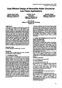
ABSTRACT Reversible logic is becoming an important research area which aims mainly to reduce power dissipation during computing. In this paper we introduce a new parity preserving reversible gate PPPG (a 5x5 gate). This gate is universal in the sense it can synthesize any arbitrary Boolean function. It is also a parity preserving gate in which the parity of input matches the parity of the output. This parity preserving gate allows any single fault to be detected at the circuit’s primary outputs. By using one PPPG a fault tolerant reversible full adder circuit can be realized. The proposed fault tolerant full adder (PFTFA) is used to design other arithmetic logic circuits for which it is used as the fundamental building block. The PFTFA gate is also used to implement high speed adders which are efficient basic building blocks of logic circuits. It has also been demonstrated that the proposed high speed adders are efficient in terms of gate count, garbage outputs and constant inputs than the existing counterparts.
KEYWORDS Reversible logic, Garbage output, Reversible gate, Proposed Parity Preserving Gate, Constant inputs and Proposed fault tolerant full adder, Carry Skip Adder, Carry Look Ahead Adder, Ripple carry Adder
1. INTRODUCTION Today’s computing world is in the quench of ultra low power dissipation. With the advancement of technology, complex systems are obtained with high clock frequency for a greater speed and an increase in packing the transistors on a chip which results more power consumption. All the logical operations performed by millions of gates in a conventional computer are irreversible. That is, whenever a logical operation is performed information about the input is erased or lost and is dissipated in heat. An irreversible logic computation generates kTln2 joules of heat energy for each bit of information lost, where k is Boltzmann’s constant and T the absolute temperature at which computation is performed [14], which was proved by Researchers like Landauer. When a computation is performed in a reversible way [2], Bennett showed that kTln2 energy dissipation would not occur, as there is a direct relationship between the amount of energy dissipated in a system and the number of bits erased during computation. Circuits that do not lose information are said to be Reversible. Only when the system comprises of reversible gates, reversible computation in a system can be achieved. Reversible circuits can produce unique output for distinct input combination, and vice versa. In the reversible circuits, there is a one-to-one mapping between input and output vectors. DOI : 10.5121/vlsic.2012.3308
83
International Journal of VLSI design & Communication Systems (VLSICS) Vol.3, No.3, June 2012
Bennett’s theorem [2] about heat dissipation is only a necessary but not sufficient condition, but its extreme importance lies in the fact that every future technology will have to use reversible gates to reduce power. For every 18 months the processing power doubles according to Moore’s law. The present irreversible technologies dissipate a lot of heat which reduces the life of the circuit. Information is not erased in reversible logic operations which in turn dissipates very less heat. In future the reversible logic will be the prominent technology in the field of low power high performance circuits. Synthesis of reversible logic circuits differs from the combinational circuits in many ways [10]. In Reversible circuit each output cannot be used more than once, it means there should be no fan-out and for each unique output pattern there should be a input pattern. Finally, the resulting circuit must be acyclic which means the output should feed not more than one input. Any reversible gate performs the permutation of its input patterns only and realizes the functions that are reversible. If a reversible gate has k inputs, and therefore k outputs, then it is a kxk reversible gate. Any reversible circuit design includes only the gates that are reversible. In a reversible circuit, the outputs that are not used as primary outputs or as an input to the other gate are called as garbage outputs. The input lines that are set to constants are termed as constant inputs. An efficient design should keep the number of garbage outputs and constant inputs to minimum. Fault tolerance is the property that enables a system to continue operating properly in the event of the failure of some its components. The detection and correction of faults become easier and simple when the system is incorporated with fault tolerant components. Fault tolerance is obtained by parity in communication and many other systems. So the development of fault tolerant reversible systems in nanotechnology is motivated by parity preserving reversible circuits. A gating network is said to be parity preserving when its individual gate is parity preserving [18]. So, parity preserving reversible circuits require parity preserving reversible logic gates to construct. A new 5x5 Parity Preserving Logic Gate, PPPG is proposed. PPPG is a parity preserving gate, that is, the parity of the outputs matches the parity of the inputs. PPPG is universal in the sense that it can be used to synthesize any arbitrary Boolean function. By using only one PPPG a fault tolerant reversible full adder circuit can be realized. The presented design does not produce any unnecessary garbage outputs. Minimizing the number of garbage outputs are the major concern in reversible logic design [10]. The presented PFTFA block can be used to realize other fault tolerant arithmetic logic circuits in nanotechnology such as ripple carry adder, carry look-ahead adder and carry-skip adder.
1.1 Reversible Logic Gates 1.1.1. Basic Reversible Gates A gate where inputs can be recovered from its outputs is called a reversible gate. A reversible gate involves bijective function having k inputs and k outputs. So far many reversible gates are implemented. Among them 2x2 Feynman gate [18] (shown in Figure 1a), 3x3 Fredkin gate [18] (shown in Figure 1d), 3x3 Toffoli gate [18] (shown in Figure 1c) and 3x3 Peres gate [18] (shown in Figure 1b) are the most referred. Some of the gates are one-through gates which are Feynman (FG), Fredkin (FRG) and Peres (PG) gates, that is, one of the input line is identical to one of the output line. Some gates are two-through like Toffoli gate, that is, two of its inputs are identical to two of its outputs. The sufficient conditions for a gate to become reversible are an equal number of input and output lines and for every unique output combination there should be unique input combination.
84
International Journal of VLSI design & Communication Systems (VLSICS) Vol.3, No.3, June 2012
Figure1a.Feynman gate
Figure 1b.Peres gate
Figure1c.Toffoli gate
Figure1d.Fredkin gate
1.1.2. Parity Preserving Reversible Gates A reversible gate is called parity preserving reversible gate if its input parity matches the parity of its output. The parity preserving of a reversible logic gate can be defined as the EX-OR of the all inputs should be equal to the EX-OR of the all outputs . A few parity preserving logic gates have been presented in the paper. Among them 3*3 Feynman Double gate (F2G) [18] depicted in Figure 2a and 3*3 Fredkin gate (FRG) [18] depicted in Figure 2b are one through gates, which means one of the inputs is also output. Recently a new 3*3 parity preserving reversible gate, namely New Fault Tolerant gate (NFT) [18] depicted in Figure 2c, a 4*4 parity preserving HC gate (PPHCG) [18] depicted in Figure 2d and a 4*4 parity preserving IG gate [18] depicted in Figure 2e have been proposed.
Figure2a F2G
Figure2 FRG
Figure 2c.NFT gate Figure2d. PPHCG gate Figure 2e IG gate
1.1.3. A New 5x5 Parity Preserving Reversible Gate This paper presents a new 5x5 parity preserving reversible gate, PPPG, depicted in Figure 3a. When one of the input variables is also output then the gate is called one-through. This gate is an one-through gate. The truth table of the gate is shown in Table 1. The input pattern corresponding to particular output pattern is uniquely determined from the truth table. The proposed reversible PPPG is parity preserving. This is readily verified by comparing the parity of the input to the parity of the output that is A B C D E and P Q R S T. The newly proposed PPPG gate is universal in the sense that it can be used for implementing any arbitrary Boolean functions.
Figure 3a PPPG gate
Figure 3b PPPG as AND and XOR 85
International Journal of VLSI design & Communication Systems (VLSICS) Vol.3, No.3, June 2012
Figure 3c PPPG as NOT and OR Table 1. Truth Table of the Parity Preserving Proposed Gate A
B
C
D
E
P
Q
R
S
T
0
0
0
0
0
0
0
0
0
0
0
0
0
0
1
0
0
0
0
1
0
0
0
1
0
0
0
1
0
0
0
0
0
1
1
0
0
1
0
1
0
0
1
0
0
0
1
1
1
0
0
0
1
0
1
0
1
1
1
1
0
0
1
1
0
0
1
0
0
1
0
0
1
1
1
0
1
0
0
0
0
1
0
0
0
0
1
1
0
1
0
1
0
0
1
0
1
1
0
0
0
1
0
1
0
0
1
0
1
0
0
1
0
1
1
0
1
0
1
1
0
1
1
0
0
0
0
0
1
1
0
1
1
0
1
0
0
0
1
0
0
1
1
1
0
0
0
1
1
1
0
1
1
1
1
0
0
1
1
0
1
0
0
0
0
1
1
1
0
0
1
0
0
0
1
1
1
1
0
1
1
0
0
1
0
1
1
0
1
1
1
0
0
1
1
1
1
0
1
0
1
0
1
0
0
1
1
1
1
0
1
0
1
0
1
1
1
1
1
1
1
0
1
1
0
1
1
0
0
1
1
0
1
1
1
1
1
0
0
0
1
1
0
0
0
1
0
0
1
0
1
1
0
0
1
1
0
0
1
1
1
1
0
1
0
1
0
1
1
0
1
1
0
1
1
1
0
1
1
1
1
1
1
0
0
1
0
0
0
0
1
1
1
0
1
1
0
0
0
1
1
1
1
1
0
1
0
1
0
0
1
1
1
1
1
1
0
1
0
1
86
International Journal of VLSI design & Communication Systems (VLSICS) Vol.3, No.3, June 2012
1.2. Fault Tolerant Reversible Full Adder Circuit Reversible logic implementation of full adder circuit has been studied by several authors in the literature [10-18]. With at least one constant input and two garbage outputs a reversible full adder circuit can be realized. This requirement is not the same for fault tolerant reversible full adder circuit. Because in a fault tolerant full adder circuit the input parity must matches the parity of the outputs. This section first establishes the minimum number of garbage outputs and constant inputs required to design a fault tolerant reversible full adder circuit and then proposes a new realization of fault tolerant reversible full adder circuit using the newly proposed PPPG gate. Theorem 1: Any realization of a fault tolerant reversible full adder circuit needs at least three garbage outputs and two constant inputs. Proof: The full adder circuit output equations S=A B Cin and Cout= (A B)Cin AB produce the same output S=1 and Cout=0, for the three distinct input combinations A=0, B=0, Cin=1; A=0, B=1,Cin=0 and A=1, B=0, Cin=0. The parity of the input vector matches the parity of the corresponding output vector. To separate all repeated values of outputs S and Cout as well as keeping their parity unchanged, at least three garbage outputs are required. Thus the total number of outputs is 2+3=5. Now since in a reversible circuit the number of inputs must be equal to the number of outputs and there are three inputs in a full adder circuit A, B and Cin, the other two inputs need to be constant inputs. There are three fault tolerant reversible full adder circuits in the literature [3][10][11][18]. The fault tolerant full adder circuit in [6] requires six parity preserving reversible gates (two FRGs and four F2Gs) and the fault tolerant full adder circuit in [3] uses four FRGs. This paper presents a new design of fault tolerant reversible full adder circuit namely “Proposed Fault Tolerant Full Adder (PFTFA)” that uses only one PPPG, depicted in Figure 4. It requires only one clock cycle.
Figure 4.Fault tolerant reversible full adder using PPPG
2. APPLICATIONS OF THE PROPOSED GATE (PG) To illustrate the applications of the proposed gate, two types of adders – ripple carry, carry lookahead adder and carry skip adders are designed. The adders implemented using the Proposed Gate are most optimized in terms of reversible gates compared to their existing counter parts.
2.1. Ripple Carry Adder The ripple carry adder is implemented using full adder as the basic building block. The fault tolerant reversible ripple carry adder is obtained by cascading a series of fault tolerant reversible full adders as shown in figure 5.
87
International Journal of VLSI design & Communication Systems (VLSICS) Vol.3, No.3, June 2012
Cout
B3 A3 0 0
B2 A2 0 0
B1 A1 0 0
B0 A0 0 0
PFTFA
PFTFA
PFTFA
PFTFA
S4 G11 G10 G9
S3 G8 G7 G6
S2 G5 G4 G3
S0 G2 G1 G0
Cin
Figure 5. Ripple Carry Adder Using The PFTFA The output expressions for a ripple carry adder are: Si = A⊕ B⊕ Cin; Cout= (A⊕B)Cin ⊕AB; It can be inferred, from the Fig. 6 that for N bit addition, the proposed ripple carry adder architecture uses only N reversible gates and produces only 3N garbage outputs. But, the ripple carry adder using our proposed gate (PG) is the most optimized one. Table III shows the result that compares the proposed ripple carry adder using PG gate, with the existing full adders of. It is observed that the proposed circuit is better than the existing circuits; both in terms of reversible gates and garbage outputs.
2.2. Carry Look-Ahead Adder By reducing the time required to produce the carry fast adders can be designed. One way of computing is, the input carry of stage i can be obtained from all the carry signals of preceding stages like i-1,i-2,……0, than waiting for a carry to pass slowly from one stage to another stage. Carry look-ahead adders use the above principle. By using parallel carry computations high speed can be achieved in Carry look-ahead adders (CLA) compared to other adders. Generation or Propagation of a carry is determined by the bit pair, in the binary sequence to be added, from CLA logic. Carry ahead of time is determined by the pre-process of the two numbers being added. The ripple carry effect is eliminated when the actual addition is performed. The adder is based on the fact that a carry signal will be generated in two cases: 1. When both bits Ai and Bi are 1, or 2. When one of the two bits is 1 and the carry-in is 1. Thus, Cout = Ci+1 = Ai . Bi + (Ai ⊕ Bi) . Ci The above expression can also be represented as: Ci+1 = Gi + Pi . Ci. Where, Gi = Ai . Bi and Pi = Ai ⊕ Bi Applying this to a 4-bit adder: (1) C1 = G0 + P0 C0 (2) C2 = G1 + P1 C1 88
International Journal of VLSI design & Communication Systems (VLSICS) Vol.3, No.3, June 2012
= G1 + P1 G0 + P1 P0 C0 (3) C3 = G2 + P2 C2 = G2 + P2 G1 + P2 P1 G0 + P2 P1 P0 C0 (4) C4 = G3 + P3 C3 = G3 + P3 G2 + P3 P2 G1 + P3 P2 P1 G0 + P3 P2 P1 P0 C0 The Sum signal can be calculated as follows: Si = Ai ⊕ Bi ⊕ Ci = Pi ⊕ Ci The CLA can be broken up into two modules: 1. Proposed Gate as Full Adder (PFA): This generates Gi, Pi, and Si. 2. Carry Look-Ahead Logic: The CLA generates the carry-out bits
Figure 6. Carry look Ahead adder using PPPG
2.3. Carry Skip Adder The carry-propagation delay is reduced using carry skip adder by skipping some consecutive adder stages. The carry-skip adder consumes less power and requires less chip area compared to the carry look-ahead adder ,but comparable in speed. The addition of two binary digits at stage i, of the ripple carry adder depends on the carry in, Ci , which in reality is the carry out, Ci-1, of the previous stage. The carryout of the previous stage is directly given to the carry-in of the next stage. Therefore, in order to calculate the sum and the carry out, Ci+1 , of stage i, it is imperative that the carry in, Ci, be known in advance. It is interesting to note that in some cases Ci+1 can be calculated without knowledge of Ci .Boolean Equations of a Full Adder Pi = Ai ⊕ Bi ---- carry propagate of ith stage Si = Pi ⊕ C i ---- sum of ith stage Ci+1 = AiBi + PiCi -----carry out of ith stage Supposing that Ai = Bi, then Pi would become zero. This would make Ci+1 to depend only on the inputs Ai and Bi, without needing to know the value of Ci. If Ai = Bi = 0 then Ci+1 = AiBi = 0 If Ai = Bi = 1 then Ci+1 = AiBi = 1 Hence carry out can be computed at any stage of the addition. These findings would enable us to build an adder whose average time of computation would be proportional to the longest chains of zeros and of different digits of A and B. 89
International Journal of VLSI design & Communication Systems (VLSICS) Vol.3, No.3, June 2012
If A and B are different digits then next stage carry will be previous stage only. If both the inputs are different then Pi will be one. Then the generate term will be zero but Pi is one. So previous stage carry will be propagated to next stage. If Ai Bi is ‘one’ then Ci+1 will become Ci . When two bits of opposite value is compared , the carry out will be equivalent to the carry in of the respective stage. Hence simply the carry can be propagated to the next stage without having to wait for the sum to be calculated.
Figure 7. carry skip adder using PPPG
3. RESULTS Table 2 Comparative Experimental Results of Different Fault Tolerant 1-Bit Full Adder Circuits Design
No. of Reversible Gates
Constant inputs
Garbage outputs
Proposed Circuit 1-bit FTFA [18] 1-bit FTFA[10][11] 1-bit FTFA [3]
1 2 2 4
2 2 2 2
3 3 3 3
90
International Journal of VLSI design & Communication Systems (VLSICS) Vol.3, No.3, June 2012
Table 3 Comparative Experimental Results of Different Fault Tolerant 4-Bit Ripple Carry Adder Circuits Design
No. of Reversible Gates
Constant inputs
Garbage outputs
4-bit RCA using Proposed Gate
4
8
12
4-bit RCA[18] 4-bit RCA[10][11] 4-bit RCA[3]
8 8 8
8 8 8
12 12 12
Table 4 Comparative Experimental Results of Different Fault Tolerant 4-Bit Carry Skip Adder Circuits Design 4-bit CSA using Proposed Gate 4-bit CSA[18] 4-bit CSA[3]
No. of Reversible Gates 4 PFTFA + 4 NFT +2 F2G=10 8 MIG + 4 NFT + 2 F2G=14 20 FRG
Constant inputs
Garbage outputs
15
19
15
19
11
16
Table 5 Comparative Experimental Results of Different Fault Tolerant 2-Bit Carry Look Ahead Adder Circuits Design 2-bit CLA using Proposed Gate 2-bit CLA[18]
No. of Reversible Gates 2 PFTFA + 5 NFT +10 F2G=17 4 MIG + 5 NFT +10 F2G=19
Constant inputs
Garbage outputs
26
28
26
28
4. CONCLUSION The main aim of this paper is the proposal of a new 5x5 parity preserving reversible gate called PPPG gate and demonstrates its universality by realizing all possible Boolean functions. The proposed gate is being used to design optimized architectures of fault tolerant reversible ripple carry adder, carry look ahead adder and carry skip adder. It is proved that the adder architectures using the proposed gate are better than the existing counterparts in literature, in terms of number of reversible gates and garbage outputs. All the proposed architectures are analysed in terms of technology independent implementations. In low power CMOS, nanotechnology, and quantum computing reversible logic is widely used. The proposed parity preserving reversible gate (PPPG) and efficient fault tolerant adder architectures are one of the contributions to reversible logic. The proposed circuits can be used to design large reversible systems. In a nutshell, the advent of reversible logic will significantly contribute in reducing the power consumption.
91
International Journal of VLSI design & Communication Systems (VLSICS) Vol.3, No.3, June 2012
REFERENCES [1]
Alberto Leporati, Claudio Zandron, Giancarlo Mauri, ‘Simulating the Fredkin Gate with Energy Based P Systems’, Journal of Universal Computer Science,vol 10, pp 600- 619.
[2]
Bennett. C.H, (1973) “Logical Reversibility of Computation”, IBM J.Research and Development, pp 525-532.
[3]
Bruce J. W, Thornton. M. A, Kumaraiah. L, Kokate. P.S, Li, (2002) “Efficient Adder Circuits Based on a Conservative Reversible Logic Gates”, In Proc. of IEEE Computer Society Annual Symposium on VLSI, Pittsburg, PA, pp 83-88.
[4]
Fredkin.E And Toffoli. T, (1982)“Conservative Logic’, Intl. Journal of Theoretical Physics, pp 219253.
[5]
Feynman. R, (1985) “Quantum Mechanical Computers”, Optical News, vol 11, pp 11-20.
[6]
Haghparast. M And Navi. K, (2008) “A Novel Fault Tolerant Reversible Gate for Nanotechnology Based Systems”, Am. J. of App. Sci.,vol 5, pp 519-523.
[7]
Islam. M. S, Islam. M. R, Karim. M. R, Mahmud. A. A and Babu. H. M. H, (2004) “Variable block carry skip logic using reversible gates”, In Proc. Of 10th International Symposium on Integrated Circuits, Devices & Systems, Singapore, pp 9-12.
[8]
Islam. M. S, Islam. M. R, Karim. M. R, A. A. M. and Babu. H. M. H, (2004) “Minimization of adder circuits and variable block carry skip logic using reversible gates”, In Proc. of 7th International Conference on Computer and Information Technology, Dhaka, Bangladesh, pp 378-383.
[9]
Islam. M. S, Rahman. M. M, Begum. Z and Hafiz. M. Z, (2009) “Low cost quantum realization of reversible multiplier circuit”, Information Technology Journal, vol 8,pp 208-213.
[10] Islam. M. S, Rahman. M. M, Begum.Z, Hafiz. M. Z and Mahmud. A. A, (2009) “Synthesis of fault tolerant reversible logic circuits”, In Proc. IEEE International Conference on Testing and Diagnosis, Chengdu, China, pp 28- 29. [11] Islam. M. S and Begum. Z, (2008) “Reversible logic synthesis of fault tolerant carry skip BCD adder’, Bangladesh Academy of Science Journal, vol 32, pp193-200. [12] Islam. M. S And Islam. M. R, (2005) “Minimization of Reversible Adder Circuits”, Asian Journal of Information Technology, vol 4, pp 1146-1151. [13] James R. K, Shahana T. K., Jacob. K. P. And Sasi. S,(2007)“Fault Tolerant Error Coding and Detection using Reversible Gates’, IEEE TENCON, pp 1- 4. [14] Landauer.R, (1961) “Irreversibility and Heat Generation in the Computational Process’, IBM Journal of Research and Development, vol 5,pp 183-191. [15] Parhami , (2006) “Fault Tolerant Reversible Circuits’, In Proc. of 40th Asimolar Conf. Signals, Systems, and Computers, Pacific Grove, CA, pp 1726-1729. [16] Peres. A, (1985) “Reversible Logic and Quantum Computers’, Physical Review: A, vol 32, pp 32663276. [17] Parhami. B , (2006) “Fault tolerant reversible circuits’, In Proceedings of 40th Asimolar Conf. Signals, Systems, and Computers, Pacific Grove, CA, pp 1726-1729
92
International Journal of VLSI design & Communication Systems (VLSICS) Vol.3, No.3, June 2012 [18] Saiful Islam. Md, Muhammad Mahbubur Rahman, Zerina begum, and Mohd. Zulfiquar Hafiz,(2010) “Efficient Approaches for Designing Fault Tolerant Reversible Carry Look-Ahead and Carry-Skip Adders”, The Computing Research Repository (CoRR). [19] Toffoli. T, (1980) “Reversible Computing”, Tech memo MIT/LCS/TM-151, MIT Lab for Computer Science . [20] Toffoli. T, (1980) “‘Reversible Computing, Automata, Languages and Programming”, SpringerVerlag , pp 632-644.
Authors Mr.KrishnaMurthy Madaka obtained his B.Tech and M.Tech degrees from JNT Universties. He is currently working as Assistant professor in MVGR College of Engineering, Vizianagaram,AP. His areas of interest are VLSI, Microcontrollers.
Ms.G.Gayatri completed her B.Tech Degree from MVGR college of Engineering, JNT University, Kakinada in the year 2012.Her Areas of interests are VLSI, Microcontrollers.
Mr.R.Manoj Kumar obtained his B.Tech Degree from VITAM college of Engineering, JNT University, Kakinada in the year 2010. He is currently pursuing his M.Tech from MVGR College of Engineering, JNT University, Kakinada. His areas of interests are VLSI, Embedded Design.
93