sensors Article
Examination of Inertial Sensor-Based Estimation Methods of Lower Limb Joint Moments and Ground Reaction Force: Results for Squat and Sit-to-Stand Movements in the Sagittal Plane Jun Kodama 1 and Takashi Watanabe 2, * 1 2
*
Graduate School of Engineering, Tohoku University, Sendai, Miyagi 980-8579, Japan;
[email protected] Graduate School of Biomedical Engineering, Tohoku University, Sendai, Miyagi 980-8579, Japan Correspondence:
[email protected]; Tel./Fax: +81-22-795-4861
Academic Editors: Yun Liu, Han-Chieh Chao, Pony Chu and Wendong Xiao Received: 26 April 2016; Accepted: 27 July 2016; Published: 1 August 2016
Abstract: Joint moment estimation by a camera-based motion measurement system and a force plate has a limitation of measurement environment and is costly. The purpose of this paper is to evaluate quantitatively inertial sensor-based joint moment estimation methods with five-link, four-link and three-link rigid body models using different trunk segmented models. Joint moments, ground reaction forces (GRF) and center of pressure (CoP) were estimated for squat and sit-to-stand movements in the sagittal plane measured with six healthy subjects. The five-link model and the four-link model that the trunk was divided at the highest point of the iliac crest (four-link-IC model) were appropriate for joint moment estimation with inertial sensors, which showed average RMS values of about 0.1 Nm/kg for all lower limb joints and average correlation coefficients of about 0.98 for hip and knee joints and about 0.80 for ankle joint. Average root mean square (RMS) errors of horizontal and vertical GRFs and CoP were about 10 N, 15 N and 2 cm, respectively. Inertial sensor-based method was suggested to be an option for estimating joint moments of the trunk segments. Inertial sensors were also shown to be useful for the bottom-up estimation method using measured GRFs, in which average RMS values and average correlation coefficients were about 0.06 Nm/kg and larger than about 0.98 for all joints. Keywords: joint moment; inertial sensor; trunk model; ground reaction force; center of pressure
1. Introduction Elderly persons with decreased muscle strength and motor disabled subjects have some difficulties in their daily life. Especially, lower motor functions such as sit-to-stand and walking are important for independent daily life. Therefore, those subjects need rehabilitation training to improve or restore their motor functions. For the rehabilitation training, evaluation of motor function of the subjects is necessary to determine rehabilitation program. Recently, inertial sensors have been used to evaluate motor function: assessment of lower motor function for knee osteoarthritis patients [1], balance and knee extensibility evaluation of hemiplegic gait [2], effect of robotic gait rehabilitation [3], effect of drop foot correction by FES [4], gait analysis for outcome measurement after knee arthroplasty [5], and assessment of daily-life reaching performance after stroke [6]. Most of the studies using inertial sensors measure movement time, calculate joint or inclination angles, walking speed, step or stride length and segment position relative to other position, and detect gait event timings. Joint moments also make it possible to evaluate muscle strength, training effect of rehabilitation and so on. Especially, lower limb joint moments have been studied for evaluation of muscle strength Sensors 2016, 16, 1209; doi:10.3390/s16081209
www.mdpi.com/journal/sensors
Sensors 2016, 16, 1209
2 of 19
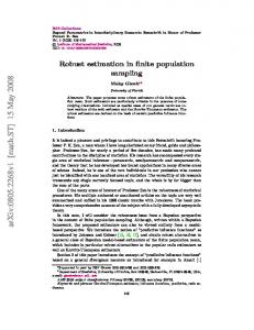
in relation to balance recovery performance [7,8]; movement strategies [9,10] of elderly subjects, and in evaluation of individuals with Parkinson's disease [11], hemiparesis [12] and cerebral palsy [13,14]; and used as evaluation indexes for rehabilitation [15–17], joint arthroplasty [18–20] and tuning of ankle-foot orthoses [21,22]. These various studies show that joint moments can be useful as one of quantitative indexes of rehabilitation. However, joint moments cannot be measured directly during movements in daily living. Generally, joint moments are estimated by an indirect way from data measured with a camera based 3D motion measurement system and a force plate system using a bottom-up inverse dynamics analysis [23]. Since the moment estimation method using these systems (conventional method) limits measurement environment and is costly, the estimation of joint moments is limited to the use in laboratories and major hospitals. In order to eliminate the limitations in the conventional joint moment estimation method, a wearable system consisting of inertial sensors and force sensors has been studied [24,25]. In addition, estimates of back load using top-down inverse dynamics analysis for data measured with 17 inertial sensors for 16 body segments has been found to closely correspond to laboratory-based systems [26]. The sensor-based method can remove the limitation of the conventional method and reduce its cost for the measurement systems, and the joint moment estimation is considered to be easier to use by decreasing the number of sensors. Since moment estimation method only using inertial sensors uses a top-down inverse dynamics analysis [27,28], modeling of multi-joint segments of the trunk is an important issue for reliability and practicality of estimation of lower limb joint moments with inertial sensors. As Zijlstra et al. reported that a segmented trunk model yielded better results in estimation of hip abduction moment than a rigid trunk model [29], a segmented trunk model is considered to be effective for estimation of lower limb joint moments rather than a rigid trunk model. This paper aims to evaluate quantitatively inertial sensor-based estimation methods of joint moments and ground reaction forces using five-link, four-link and three-link rigid body models that consist of different trunk models (three-segmented trunk model, two-segmented model and a rigid trunk model). Especially, lower limb joint moments in the sagittal plane were the focus, and sit-to-stand and squat movements were measured, because lower limb joint moments in the sagittal plane have been used in various studies, as mentioned above, and such movements were considered to be suitable for evaluating trunk segmented models. Lower limb joint moments and ground reaction forces (GRF) during squat and sit-to-stand movements were estimated with two methods using inertial sensors, and compared to those estimated by the conventional method using camera-based 3D motion measurement system and a force plate. The joint moments were also estimated by a camera-based estimation method without a force plate in order to evaluate difference between the top-down and the bottom-up methods. Then, estimation methods of joint moments and ground reaction forces using inertial sensors were discussed considering easiness of setting of the measurement devices. 2. Materials and Methods 2.1. Rigid Body Link Model Human body was represented by the rigid body link model and assumed that each segment moves in the sagittal plane symmetrically and the feet were fixed on the ground. Figure 1 shows rigid body link models tested in this paper. Based on the five-link model, in which the trunk was divided into three segments based on Young et al. [30], three other types of trunk models were constructed: two-segmented trunk model divided at the lower end of the rib (four-link-R model), two-segmented trunk model divided at the highest point of the iliac crest (four-link-IC model) and a rigid trunk model (three-link model). The head and the arm segments were included in the top segment of each link model. Body segment parameters (i.e., segment length and mass, center of mass position and moment of inertia) were calculated based on the inertial properties of body segments of young Japanese athletes as reported by Ae et al. [31]. Since Ae et al. used a model that divided the trunk into upper and lower parts
Sensors 2016, 16, 1209
3 of 20
segment SensorsBody 2016, 16, 1209
parameters (i.e., segment length and mass, center of mass position and moment 3 of 19 of inertia) were calculated based on the inertial properties of body segments of young Japanese athletes as reported by Ae et al. [31]. Since Ae et al. used a model that divided the trunk into upper atand thelower lower parts end ofatthe rib, values of body parameters the four-link-R model calculated the lower end of thesegment rib, values of bodyofsegment parameters ofwere the four-link-R first. Then, those values were converted to those of the five-link model by modeling the middle trunk as model were calculated first. Then, those values were converted to those of the five-link model by an elliptic cylinder with trunk uniform based on the method of calculating segment modeling the middle as density an elliptic cylinder with uniform densitybody based on theparameters method of of the total system [23], in parameters which the value the density by Clauser et al.of [32] size calculating body segment of theoftotal system reported [23], in which the value theand density parameters obtained from the Advanced Industrial Science and Technology (AIST) Human body reported by Clauser et al. [32] and size parameters obtained from the Advanced Industrial Science size [33] were used. After body that, body the four-link-IC anddatabase Technology (AIST) Human size segment databaseparameters [33] were of used. After that, and bodythree-link segment models were calculated from those of the five-link model and the four-link-R model, parameters of the four-link-IC and three-link models were calculated from those of respectively, the five-link by combining segmentsmodel, [23]. That is, the upper and the middle trunk segments of the five-link model and thetwo four-link-R respectively, by combining two segments [23]. That is, the upper model were combined into the upper-middle trunk of the four-link-IC model and the upper and the and the middle trunk segments of the five-link model were combined into the upper-middle trunk middle-lower trunk segments of the four-link-R model were combined into the head, arm and trunk of the four-link-IC model and the upper and the middle-lower trunk segments of the four-link-R (HAT) of the three-link The calculated body segment are shown modelsegment were combined into themodel. head, arm and trunkvalues (HAT)ofsegment of the parameters three-link model. The in Table 1. Here, foot segment was model by a triangle and height of the center of mass (CoM) of foot calculated values of body segment parameters are shown in Table 1. Here, foot segment was model segment was assumed to of bethe 3 cm. by a triangle and height center of mass (CoM) of foot segment was assumed to be 3 cm.
upper trunk
middle trunk
a b
lower trunk
c
5-link
upper trunk a
c
upper-middle trunk
middle-lower trunk
4-link-R
b c
lower trunk
4-link-IC
HAT
c
3-link
Figure Figure1.1.Multi-link Multi-linkmodels modelstested testedin inthis thispaper. paper.a,a,b,b,and andccshow showthe thelower lowerend endofofthe therib, rib,the thehighest highest point of the iliac crest and the great trochanter, respectively. point of the iliac crest and the great trochanter, respectively. values of body segment parameters. Ratios Ratios of segment length (%height), segment Table Table1.1.Calculated Calculated values of body segment parameters. of segment length (%height), mass (%weight), and centerand of mass location from the distal radius gyration segment mass (%weight), center of mass location fromend theand distal end of and radius (%segment of gyration length) are shown. (%segment length) are shown. Segment
Segment
SegmentSegment Length 14.8Length 23.0 14.8 23.9 8.1 23.0 3.0 23.9 37.8 8.1 11.1 40.8 3.0 48.9 37.8
Mass
Mass
Mass CenterCenter of Massof Location
1.1 5.1 1.1 11.0 15.4 5.1 3.3 11.0 46.9 15.4 18.7 50.2 3.3 65.646.9
Location 0.595 0.594 0.595 0.525 0.594 0.397 0.500 0.525 0.331 0.397 0.391 0.500 0.358 0.371 0.331
Radius of Radius of Gyration
Gyration 17.7 27.4 17.7 27.8 27.4 52.5 97.4 27.8 26.9 52.5 42.5 97.4 25.6 25.5 26.9 middle-lower 11.1 18.7 0.391 42.5 2.2. Estimation of Joint Moment 40.8 upper-middle 50.2 0.358 25.6 HAT 48.9 65.6 0.371 25.5 Joint moments were estimated by solving equations of translational motion and rotational motion of the CoM of each segment. Figure 2 shows definitions of inclination angles, joint moments and joint 2.2. Estimation of Joint Moment reaction forces for the five-link model of human body. The origin of the coordinate system was set at ankle Joint position, in which heelestimated position was 3.1 (%height) and ´4.2 (%height). motion and rotational moments were by solving equations of translational The five-link model consists of the foot, the shank (i = 1), the thigh (i = 2), the lowerjoint trunk (i = 3), motion of the CoM of each segment. Figure 2 shows definitions of inclination angles, moments the middle trunk (i = 4) and the upper trunk (i = 5). The segment numbers were assigned from the foot shank foot thigh shank lower trunk middle trunk thigh upper trunk lower trunk middle-lower middle upper-middle trunk HAT upper trunk
Sensors 2016, 16, 1209
4 of 20
and joint reaction forces for the five-link model of human body. The origin of the coordinate system 4 of 19 was set at ankle position, in which heel position was 3.1 (%height) and −4.2 (%height). The five-link model consists of the foot, the shank (i = 1), the thigh (i = 2), the lower trunk (i = 3), the middle trunk (i = 4) and thetop upper trunk The (i = 5). The segment werei are assigned from the bottom (shank segment) to the segments. motion equationsnumbers for segment represented by bottom (shank(Figure segment) the following 2b): to the top segments. The motion equations for segment i are represented .. by the following (Figure 2b): mi X G “ Fx ´ Fx (1)
Sensors 2016, 16, 1209
i
i
i`1
𝑚 𝑋̈ = 𝐹𝑥 𝑖 − 𝐹𝑥 𝑖+1 mi Y Gi 𝑖“ 𝐺F𝑖yi ´ F ´ mi g y 𝑚𝑖 𝑌𝐺̈ 𝑖 = 𝐹𝑦 𝑖 − 𝐹𝑦i`1 − 𝑚𝑖 𝑔 .. ` ˘ 𝑖+1 ` ˘ q F q F Ii𝐼θ𝑖i𝜃“ M ´ M ` r F ` p1 ´ r l sin θ ´ r F ` p1 ´ r l cos θ ̈𝑖 = 𝑀i 𝑖 − 𝑀i` x x y y 1 i i i i i i (1 )𝐹 (1 )𝐹 + (𝑟 𝐹 + − 𝑟 )𝑙 sin 𝜃 − (𝑟 𝐹 + − 𝑟 i i`1 i i`1 𝑖+1 𝑖 𝑥𝑖 𝑖 𝑥 𝑖+1 𝑖 𝑖 𝑖 𝑦𝑖 𝑖 𝑦 𝑖+1 )i𝑙𝑖 cosi𝜃𝑖 ..
(1) (2) (2) (3) (3)
where number; mi , 𝑚 li , ,ri 𝑙and Ii are body segment parameters (segment mass, segment where i 𝑖shows showssegment segment number; 𝑖 𝑖 , 𝑟𝑖 and 𝐼𝑖 are body segment parameters (segment mass, length, CoM position fromratio the distal moment of moment inertia, respectively); Mi and Fxi and segment length, CoMratio position from end the and distal end and of inertia, respectively); 𝑀 𝑖
..
..
Fyi are𝐹𝑥joint moment andjoint jointmoment reaction forces, respectively; of segment Gi and Y Gi are accelerations and and 𝐹𝑦 𝑖 are and joint reaction Xforces, respectively; 𝑋̈𝐺 𝑖 and 𝑌𝐺̈ 𝑖 are .. 𝑖 CoM position in the horizontal and the vertical direction, respectively; θ and are inclination angle θ i direction, i accelerations of segment CoM position in the horizontal and the vertical respectively; 𝜃𝑖 and its angular acceleration, respectively; and g shows gravitational acceleration. Estimated joint ̈ and 𝜃𝑖 are inclination angle and its angular acceleration, respectively; and 𝑔 shows gravitational moments were obtained joint by substituting joint reaction calculated joint from reaction Equations (1) and (2) into acceleration. Estimated moments were obtainedforces by substituting forces calculated Equation (3). For(1) each of body segment parameters were usingparameters measured from Equations andsubject, (2) intovalues Equation (3). For each subject, values ofcalculated body segment height and weight and inclination angles were measured during movements. Accelerations of were calculated using measured height and weight and inclination angles were measured during the inclination angles and segment CoM positions were calculated using calculated body segment movements. Accelerations of the inclination angles and segment CoM positions were calculated parameters and measured inclination angles. using calculated body segment parameters and measured inclination angles.
i=5
θ5 a b c
Y X
θ4 θ3 θ2 θ1 (a)
.. YGi
i=4 i=3
Mi+1
.. Fyi+1 XGi
Fyi
i=2 i=1
Fxi+1
θi mi g Mi
Fxi (b)
segment inclination angle,angle, joint reaction force and jointand moment: inclination Figure 2.2.Definitions Definitionsof of segment inclination joint reaction force joint (a) moment: (a) angle of the five-link model, where a, b and c are landmarks of the body shown in Figure 1; and (b) joint inclination angle of the five-link model, where a, b and c are landmarks of the body shown in Figure 1; reaction forces and joint moments at segment and (b) joint reaction forces and joint momentsi. at segment i.
Joint moments were were estimated estimated using using the the following following four four methods: methods: Joint moments (1) Conventional method method (bottom-up (bottom-up method): method): The motion (1) Conventional The conventional conventional method method used used aa 3D 3D motion measurement system and a force plate. First, segment inclination angles were calculated based on measurement system and a force plate. First, segment inclination angles were calculated based on position data of markers attached on landmarks of the body. Then, segment CoM positions were position data of markers attached on landmarks of the body. Then, segment CoM positions were calculated top segment segment using using the the inclination inclination angles ratios of of calculated from from the the bottom bottom segment segment to to the the top angles and and ratios segment length and center of mass position shown in Table 1. Segment length was calculated from segment length and center of mass position shown in Table 1. Segment length was calculated from height subject. CoM height of of subject. CoM accelerations accelerations and and angular angular acceleration acceleration of of each each segment segment were were calculated calculated by by the differential with a 3rd order low-pass differential algorithm proposed by Usui et al. [34]. Here, a the differential with a 3rd order low-pass differential algorithm proposed by Usui et al. [34]. Here, zero-phase 2nd order low pass Butterworth filter with a cutoff frequency of 6 Hz [35] was applied a zero-phase 2nd order low pass Butterworth filter with a cutoff frequency of 6 Hz [35] was applied to to estimated angles calculating the differentials the differential low-pass differential the the estimated angles beforebefore calculating the differentials because because the low-pass algorithm algorithm could not reduce sufficiently high frequency noise in CoM accelerations caused could not reduce sufficiently high frequency noise in CoM accelerations caused by calculation by of calculation of the 2nd-order of CoM were estimated by solving the 2nd-order differential of differential CoM position. Jointposition. momentsJoint weremoments estimated by solving simultaneous simultaneous Equations (1)–(3) using values the calculated valuesground and measured reaction forces Equations (1)–(3) using the calculated and measured reaction ground forces from the bottom from the bottom joint to the top joint. That is, ankle joint moment was estimated first, and then, joint to the top joint. That is, ankle joint moment was estimated first, and then, knee joint moment is knee joint moment is estimated using the ankle joint moment and joint reaction forces. estimated using the ankle joint moment and joint reaction forces.
Sensors 2016, 16, 1209
5 of 19
(2) SI method (Sensor-measured Inclination angle-based method): The SI method only used inertial sensors. Joint moments were estimated from the top joint to the bottom joint using inclination angles with the assumption that no external force acts on the top segment (top-down method). Segment inclination angles were estimated from signals measured with inertial sensors by the integral of angular velocities using Kalman filter [36]. The Kalman filter was used for correcting integration error using acceleration signals measured with the sensors, in which the zero-phase 2nd order Butterworth low pass filter with a cutoff frequency of 1 Hz was applied to the acceleration signals. Then, the inclination angles were low-pass filtered by the zero-phase 2nd order Butterworth filter with a cutoff frequency of 6 Hz for the same reason as the conventional method. After that, CoM positions, CoM accelerations and angular accelerations of all segments were calculated by the same way as the conventional method using the estimated angles. Finally, joint moments were estimated by solving the simultaneous Equations (1)–(3) substituting those calculated values. (3) CI method (Camera-measured Inclination angle-based method [27,28]): The CI method used only a camera-based motion measurement system. Inclination angles, CoM positions, CoM accelerations and angular accelerations of all segments were calculated by the same way as the conventional method. Joint moments were estimated by the top-down method used in the SI method. (4) SA method (Sensor-measured Acceleration-based method): The SA method used only inertial sensors. Joint moments were estimated by the top-down method using acceleration signals measured with inertial sensors in addition to estimated segment inclination angles, which was modified as a sensor-based method from the method by Zijlstra et al. [29] because they used trunk angle calculated based on position data of markers. First, segment inclination angles were estimated by the same way as the SI method using Kalman filter and the low pass filter with a cutoff frequency of 6 Hz. Angular accelerations were calculated by the differential of measured angular velocities using the 3rd order low-pass differential algorithm. Accelerations of each segment CoM were calculated from measured accelerations with the inertial sensor attached on the CoM of its segment, in which measured acceleration signals were converted to values in the coordinate system shown in Figure 2a by the rotation matrix calculated by the estimated angles, and gravitational acceleration were removed. Here, CoM accelerations of combined segments such as the HAT segment of three-link model were calculated from acceleration signals of two inertial sensors. Joint moments were estimated by the same way as the SI method from the top to the bottom joints. 2.3. Experimental Method Six young healthy subjects (male, 21–23 years old, 176.3 ˘ 4.0 cm, 63.9 ˘ 6.4 kg) performed four types of movements five times: two types of squat movement (movement time was 6 s and 9 s) and two types of sit-to-stand movement (normal condition and condition of forward inclination of the trunk simulating elderly persons). The movements were measured with the camera-based 3D motion measurement system (OPTOTRAK, Northern Digital), two force plates (9286A, Kistler) and wireless inertial sensors (custom-made sensor modules using Bluetooth and InvenSense MPU-9150) at a sampling frequency of 100 Hz. Figure 3 shows the experimental set up. Inertial sensors were attached to the skin or on half tights (BIOGEAR A60BP, MIZUNO Corporation, Tokyo, Japan) with double-sided adhesive tape and stretch bands near the CoM positions of body segments corresponding to those of the five-link model as shown in Figure 3a. Seven inertial sensors were mounted on the upper, middle and lower trunk segments, and on the frontal and the lateral sides of the shank and the thigh of the left lower limb. Markers for the 3D motion measurement system were attached on the left side of the subject, in which attached positions were the acromion, along the long axis of the trunk at the same height as the lower end of the rib and the highest point of the iliac crest, the great trochanter, the lateral femoral condyle, and the lateral malleolus. In addition, a rigid bar on which a pair of markers was attached was mounted on each inertial sensor in order to validate inclination angles estimated by signals measured with the sensors, although the angle estimation method has been shown to estimate inclination angles of lower limbs with average root mean square (RMS) error
Sensors 2016, 16, 1209
6 of 19
Sensors 2016, 16, 1209
6 of 20
less than 4˝ for human gait movements and cyclic movements of rigid bodies [36,37]. Force plates were bodies used for measurement of ground reaction forces and load actingreaction on a stool thatand wasload used to detect [36,37]. Force plates were used for measurement of ground forces acting on a stool that was used to detect the seat-off timing. the seat-off timing. Subjects were instructed performmovements movements with folded, as seen in Figure 3b. 3b. Subjects were instructed totoperform withtheir theirarms arms folded, as seen in Figure The sound of metronome was presented to the subjects for regulating movement speed. Measured The sound of metronome was presented to the subjects for regulating movement speed. Measured data data were evaluated in estimation of segment angles first. Here, both of angles measured with the were evaluated in estimation of segment angles first. Here, both of angles measured with the 3D 3D motion measurement system and estimated with inertial sensors were calibrated using angles motion measurement system and estimated with inertial sensors were calibrated using angles during during quiet standing for 0.5 s. Significant differences were evaluated using t-test with Bonferroni quietcorrection. standing for 0.5 s. Significant differences were evaluated using t-test with Bonferroni correction.
: marker : sensor : force plate : rigid bar mounted on the sensor
s1 a b c
s2 s3
(a)
(b)
Figure 3. Experimental of movements movementswith with inertial sensors, 3D motion Figure 3. Experimentalsetup setupofofmeasurement measurement of inertial sensors, 3D motion measurement system force plates: attachmentpositions positionsof ofinertial inertial sensors sensors and measurement system andand force plates: (a)(a) attachment and markers markersofof the the 3D measurement motion measurement and placement of force plates; and a pictureofofa asubject subject with 3D motion systemsystem and placement of force plates; and (b)(b) a picture with attached markers and sensors. attached markers and sensors.
3. Results
3. Results
Estimated inclination angles with the inertial sensors and estimated joint moments with the SI,
Estimated inclination angles withfor themovement inertial sensors joint moments withbythe SI, CI and SA methods were evaluated period. and The estimated movement period was detected CI and SA methods were evaluated forthigh movement Theand movement detected angular velocity of the shank and the for squatperiod. movement by groundperiod reactionwas force of the by angular of the shank and the thigh for squat movement and by ground reaction force of the stoolvelocity for sit-to-stand movement, respectively. stool for sit-to-stand movement, respectively. 3.1. Estimation of Inclination Angles
3.1. Estimation of Inclination Segment inclinationAngles angles estimated by signals measured with the inertial sensors were comparedinclination to those angles measured with 3D motion measurement system in sensors order towere determine Segment angles estimated by signals measured with the inertial compared sensor positions to estimate the angles for joint moment estimation. Figure 4 shows root mean to those angles measured with 3D motion measurement system in order to determine sensor positions square (RMS) errors of the inclination angles between estimation with the inertial sensors and to estimate the angles for joint moment estimation. Figure 4 shows root mean square (RMS) errors of the measurement with markers attached on landmarks of the human body, which are averaged values inclination angles between estimation with the inertial sensors and measurement with markers attached of all trials for all four movements measured with all six subjects. For the thigh and the shank on landmarks of the human body, which averaged all trials forofall four movements segments, the inertial sensors attached on are the lateral side values showedof smaller values RMS error than measured all sixonsubjects. Forside. the For thigh the shank trunk segments, theofinertial sensors attached those with of sensors the frontal theand middle-lower segment the four-link-R model, on the lateral showedon smaller values RMS error than those sensors on the frontal side. For the sensorside s3 mounted the lower trunkofshowed smaller RMS erroroffor the middle-lower trunk (MLT) than that of s2. The inclination angle of the upper-middle trunk (UMT) of the four-link-IC model middle-lower trunk segment of the four-link-R model, sensor s3 mounted on the lower trunk showed wasRMS estimated good accuracy using either sensor s1 that or s2. segmentangle of theof the smaller error with for the middle-lower trunk (MLT) than of For s2. the TheHAT inclination three-link model, sensor s2 on the middle trunk the smallest RMS error. using either upper-middle trunk (UMT) ofmounted the four-link-IC model wasshowed estimated with good accuracy sensor s1 or s2. For the HAT segment of the three-link model, sensor s2 mounted on the middle trunk showed the smallest RMS error.
Sensors 2016, 16, 1209
7 of 20
error [deg] RMS[deg] RMS error
0
frontal
lateral
shank
20 25 15 20 10 15 5 10 0 5 0
(a) lower limb thigh shank (a) lower limb 25
25 20 25 15 20 10 15 5 10 0 5
lateral
s1 UT
s2 s3 MLT
s1 (c) 4-link-R s2 s3 UT MLT
20 25 15 20 10 15 5 10 0 5 0
s1 s2 UMT
s3 LT
s1(d)s24-link-ICs3 UMT LT
s1 s2 UT MT s1 (b) 5-link s2 UT MT (b) 25 5-link error [deg] RMS[deg] RMS error
0
thigh
frontal
error [deg] RMS[deg] RMS error
20 25 15 20 10 15 5 10 0 5
7 of 19 7 of 20
25
error [deg] RMS[deg] RMS error
error [deg] RMS[deg] RMS error
Sensors 2016, 16, 1209 Sensors 2016, 16, 1209 25
20 25 15 20 10 15 5 10 0 5 0
s3 LT s3 LT
s1
s2 s3 HAT s1(e) 3-link s2 s3 HAT
Figure 4. Root (c) mean square (RMS) errors of segment inclination angles between (e) estimation 3-link with (d) 4-link-IC 4-link-R inertial sensors and measurement with markers attached on the landmarks. s1, s2 and s3 show Figure 4. 4. Root Rootmean mean square (RMS) errors of segment segment inclination angles between estimation with sensors mounted on the trunk(RMS) as shown in Figure 3a. (a)inclination RMS errorsangles calculated for the thigh andwith the Figure square errors of between estimation inertial sensors and measurement with markers attached on the landmarks. s1, s2 and s3 show sensors shank (b) RMS errors forwith the markers upper trunk (UT),on thethe middle trunk (MT) inertialsegments;and measurement attached landmarks. s1, s2and andthe s3 lower show mounted on shown in(c) Figure 3a. (a) RMS errors calculated for the thigh and the shank trunk (LT) of the thetrunk five-link model; RMS errors for(a) the upper trunk (UT) and the sensors mounted on theastrunk as shown in Figure 3a. RMS errors calculated for themiddle-lower thigh and the segments; (b)ofRMS themodel; upper trunk (UT), the middle trunk (MT)trunk and the lower trunk (LT) of trunk (MLT) the four-link-R (d)upper RMS errors for the upper-middle trunk (UMT) and the shank segments; (b)errors RMSfor errors for the trunk (UT), the middle (MT) and the lower the five-link model; (c) RMS errors for the upper trunk (UT) and the middle-lower trunk (MLT) of the lower trunk (LT) of the four-link-IC model; and (e) RMS errors for the trunk segment (HAT) of the trunk (LT) of the five-link model; (c) RMS errors for the upper trunk (UT) and the middle-lower four-link-R model; RMS errors for the trunk and the lower (LT) ofthe the three-link model. trunk (MLT) of the (d) four-link-R model; (d)upper-middle RMS errors for the(UMT) upper-middle trunk trunk (UMT) and four-link-IC model; and (e) RMS errors for the trunk segment (HAT) of the three-link model. lower trunk (LT) of the four-link-IC model; and (e) RMS errors for the trunk segment (HAT) of the
As shownmodel. in Figure 4, RMS errors of inclination angle of the middle-lower trunk (MLT) were three-link largerAs than other trunk 4, segments (UT, MT, LT and UMT). 5 showstrunk the RMS and shown in Figure RMS errors of inclination angle of theFigure middle-lower (MLT)values were larger shown in segments Figureof4,inclination RMSMT, errors of inclination angle the middle-lower trunk (MLT) were correlation coefficients between the 5of upper and the middle segments and thanAs other trunk (UT, LTangles and UMT). Figure shows the RMS values and correlation larger than other trunk segments (UT, MT, LT and UMT). Figure 5 shows the RMS values between the middle and the lower segments of the five-link model. Movements of the upper and coefficients of inclination angles between the upper and the middle segments and between the middle correlation coefficients of inclination angles andand thesit-to-stand middle segments and the segments of the trunk are shown tobetween be similarthe during movements andmiddle the lower segments of the five-link model. Movements ofupper thesquat upper and the middle segments of between and the lower segments thesit-to-stand five-link Movements ofthe thein upper performed inmiddle this study, there are squat largeofdifferences in model. movements between middle and the trunkthe are shown to bewhile similar during and movements performed this study, middle segments of theresult trunk are shown tobetween be similar squat and movements the lower This not consistent between sensors 3Dsit-to-stand motion measurement while theresegments. are large differences inis movements the during middle andand the lower segments. This result performed in thisbetween study, while large differences in movements between the middle and system. is not consistent sensorsthere and are 3D motion measurement system. the lower segments. This result is not consistent between sensors and 3D motion measurement system. landmark marker sensor sensor-attached marker
40
sensor
coefficient correkation coefficient correkation
value [deg] RMS[deg] RMS value
1.4 sensor-attached marker 1.2 30 40 1.4 1 1.2 0.8 20 30 1 0.6 0.8 0.4 10 20 0.6 0.2 0 0 0.4 10 UT-MT MT-LT UT-MT MT-LT 0.2 0 0 Figure5.5. RMS RMSvalues values andcorrelation correlation coefficientsofofinclination inclinationangles angles betweenthe theMT-LT upperand andthe the Figure and coefficients between upper UT-MT UT-MT MT-LT landmark marker
middle trunk trunk segments segments (UT-MT) trunk segments (MT-LT) of the middle (UT-MT) and andbetween betweenthe themiddle middleand andthe thelower lower trunk segments (MT-LT) of five-link UT, MT and LT are thecoefficients upper, the middle and theangles lower trunk segments, respectively. Figure 5. model. RMS values and correlation of inclination between the upper and the
middle trunk segments (UT-MT) and between the middle and the lower trunk segments (MT-LT) of
Sensors 2016, 16, 1209
8 of 19
The average values of RMS error and correlation coefficient of the inclination angles between the inertial sensors and the markers mounted on each sensor by the rigid bar are shown in Table 2. Average values of RMS error were less than 2.5˝ and correlation coefficients were larger than 0.98 showing almost 1.0 for all the segments. This shows that the angle estimation method used in this study is reliable, although the RMS errors of some segments were large, as shown in Figure 4. Therefore, sensor s2 was used for the HAT segment of the three-link model and s3 was used for the lower-middle trunk of the four-link-R model. For the upper-middle trunk segment of the four-link-IC model, both sensors s1 and s2 were used for estimation of joint moments, since both of them showed values of RMS error less than 3˝ on average. Table 2. RMS errors and correlation coefficients of segment inclination angles between estimation with inertial sensors and measurement with markers mounted on their sensors by the rigid bar. s1, s2 and s3 are the sensors mounted on the trunk shown in Figure 3a. Segment
Position
RMSE (˝ )
CC
thigh
frontal lateral
2.33 ˘ 0.69 2.34 ˘ 0.80
1.00 ˘ 0.00 1.00 ˘ 0.00
shank
frontal lateral
0.60 ˘ 0.33 0.59 ˘ 0.31
1.00 ˘ 0.00 1.00 ˘ 0.00
trunk
s1 s2 s3
1.39 ˘ 0.88 0.94 ˘ 0.52 1.02 ˘ 0.70
1.00 ˘ 0.00 1.00 ˘ 0.00 0.98 ˘ 0.08
3.2. Joint Moment Estimation Using the inertial sensors that were determined in the previous section, joint moments were estimated with the four estimation methods. Figure 6 shows examples of waveforms of the joint moments estimated with five-link model for squat movement. All estimation methods showed similar waveforms. Four link models were compared in joint moment estimation for the SI, the CI and the SA methods. RMS values and correlation coefficients of estimated joint moments in comparison to those by the conventional method using a camera-based motion measurement system and a force plate are shown in Figure 7. Since body weights were different among subjects, joint moments were normalized by their body weights and those values obtained from all trials of all six subjects were averaged. For the SI method, joint moments were estimated with four-link-IC model using sensor s1 and s2, which are shown as four-link-IC (s1) and four-link-IC (s2) in the figure. All estimation methods showed that the five-link and the four-link-IC models estimated joint moments with smaller RMS values and larger values of correlation coefficient, in which the SI method showed RMS values of about 0.1 Nm/kg for all the lower limb joints, correlation coefficients of about 0.98 for the hip and the knee joints and about 0.80 for the ankle joint in average. There were no significant differences in the RMS and correlation coefficient values between the five-link and the four-link-IC models (p > 0.05). The three-link model was the worst, although RMS values for the knee joint moment were smaller than the ankle and the hip joints with the SI and the SA methods, respectively. The four-link-R model showed larger RMS values for knee joint moments than the five-link and four-link-IC models with the SI and the SA methods. Differences in the RMS and correlation coefficient values among the estimation methods were small when the five-link or four-link-IC models was used, although the SA method showed large variation of the correlation coefficients for the ankle joint moments. Figure 8 shows examples of waveforms of estimated hip joint moments with the SI and the CI methods in comparison to the rigid body link models. The three-link model overestimated the extension moments of the hip joint with both methods, which increased RMS values. Variations of RMS values shown in Figure 7 were relatively large. For example, standard deviations of the SI method with four-link models were about 0.04 Nm/kg, while average RMS
The average values of RMS error and correlation coefficient of the inclination angles between the inertial sensors and the markers mounted on each sensor by the rigid bar are shown in Table 2. Average values of RMS error were less than 2.5° and correlation coefficients were larger than 0.98 showing almost 1.0 for all the segments. This shows that the angle estimation method used in this Sensors 2016, 16, 1209 9 of 19 study is reliable, although the RMS errors of some segments were large, as shown in Figure 4. Therefore, sensor s2 was used for the HAT segment of the three-link model and s3 was used for the lower-middle trunk of the four-link-R model. For the in upper-middle segment values were about 0.1 Nm/kg. Since the RMS values shown Figure 7 weretrunk averaged valuesofof the all four-link-IC model, both and s2 types were used for estimation joint moments, since both of the data obtained with sixsensors subjectss1for four of movements, thoseofstandard deviations included them showed values of RMS error less than 3°conditions on average.and among trials. Therefore, distributions variations among subjects, among movement
1.4 1.2 1 0.8 0.6 0.4 0.2 0 -0.2 0 -0.4
2
4
4
6 8 time [s]
6 8 time [s]
10
10
12
12
Upper trunk joint moment [Nm/kg] Ext (+) / Flex (-)
Knee joint moment [Nm/kg] Ext (+) / Flex (-)
1.4 1.2 1 0.8 0.6 0.4 0.2 0 -0.2 0 -0.4
2
1.4 1.2 1 0.8 0.6 0.4 0.2 0 -0.2 0 -0.4
Lower trunk joint moment [Nm/kg] Ext (+) / Flex (-)
Hip joint moment [Nm/kg] Ext (+) / Flex (-)
1.4 1.2 1 0.8 0.6 0.4 0.2 0 -0.2 0 -0.4
Ankle joint moment [Nm/kg] P-Fxt (+) / D-Flex (-)
of RMS values and correlation coefficients were calculated separately for squat movements and for Table 2. RMS errors and correlation coefficients of segment inclination angles between estimation sit-to-stand movements (Figure 9). The RMS values for sit-to-stand movements were larger than those with inertial sensors and measurement with markers mounted on their sensors by the rigid bar. s1, for squat movements for knee and ankle joint moments (p < 0.01). Although there is no significant s2 and s3 are the sensors mounted on the trunk shown in Figure 3a. difference for the hip joint moment, variations for the squat movements were larger than the sit-to-stand movements. ThereSegment was no significantPosition difference in correlation coefficient forCC the ankle joint moment RMSE (°) (p > 0.05). Although thigh there were differences for knee and hip joint moments (p 0.05), the minimum frontal 2.33 ± 0.69 1.00 ± < 0.00 values of correlation coefficients were larger than about 0.9 for both movements. lateral 2.34 ± 0.80 1.00 ± 0.00 Then, RMS values of the six subjects were compared under the single movement condition shank frontal 0.60 ± 0.33 1.00 ± 0.00 (Figure 10). Differences of the median among the subjects were from 0.05 to 0.11 Nm/kg. On the other lateral 0.59 ± 0.31 1.00 ± 0.00 hand, ranges of distribution of RMS value between the 25th and 75th percentiles trunk s1 1.39 ± 0.88 1.00 ± 0.00were from 0.003 to 0.04 Nm/kg. Most of the distribution range s2 was less than 0.940.025 ± 0.52Nm/kg. 1.00 ± 0.00 Except for the three-link model, joint moments of the the ±trunk s3 1.02 ±link 0.70nodes of0.98 0.08 segment, that is, joint moments of the lower end of the rib and the highest point of the iliac crest, were estimated in addition lower Estimation limb joint moments. Averaged RMS values and correlation coefficients of the joint 3.2. Joint to Moment moments of the link nodes of the trunk for each estimation method are shown in Figure 11. For all Using inertial sensors that were determined the previous section, joint moments were models andthe all estimation methods, RMS values were in almost 0.2 Nm/kg and values of correlation estimated with the four estimation methods. Figure 6 shows examples of waveforms of the joint coefficients were higher than 0.95. There were no large differences between link models and between moments estimated with five-link model for squat movement. All estimation methods showed estimation methods. similar waveforms.
1.4 1.2 1 0.8 0.6 0.4 0.2 0 -0.2 0 -0.4
2
4
6 8 time [s]
10
12
2
4
6 8 time [s]
10
12
conventional method CI method
2
4
6 8 time [s]
10
SI method
SA method
12
Figure 6. Examples of waveforms of estimated joint moments during squat movement (6 s) with four estimation methods (five-link-model). “Ext” and “Flex” show extension and flexion moments, respectively. “P-Flex” and “D-Flex” show plantar flexion and dorsiflexion moments of the ankle joint, respectively.
Sensors 2016, 16, 1209
0.05 0
3-link 3-link
4-link-R
4-link-IC(s1)
4-link-R
4-link-IC(s1)
knee
ankle
knee
ankle
hip hip
(a) SI method
RMS value [Nm/kg]
RMS value [Nm/kg]
0.3 0.25 0.3 0.2 0.25 0.2 0.15 0.15 0.1 0.1 0.05 0.05 0 0
4-link-R
hip hip
knee knee
5-link
0.8 1 0.6 0.8 0.4 0.6 0.2 0.4 0.20
hip
knee
ankle
0
knee
ankle
hip
5-link
4-link-IC
4-link-R
3-link
ankle ankle
1
4-link-IC(s2)
(a) SI method
3-link
10 of 19 10 of 20
5-link
4-link-IC(s2) coefficient correlation coefficient correlation
RMS value [Nm/kg]
RMS value [Nm/kg]
0.3 0.25 0.3 0.2 0.25 0.15 0.2 0.1 0.15 0.05 0.1 0
10 of 20
5-link
4-link-IC 1
coefficient correlation coefficient correlation
Sensors 2016, 16, 1209 Sensors 2016, 16, 1209
1 0.8 0.8 0.6 0.6 0.4 0.4 0.2
0.20 knee
ankle
(b) CI method
hip
knee
ankle
0
hip
(b) CI method
4-link-IC
4-link-R
3-link 3-link
4-link-IC
1.2 1.21 1 0.8 0.8 0.6 0.6 0.4 0.4 0.2 0.2 00 -0.2 -0.2
5-link
5-link
correlation coefficient correlationcoefficient
4-link-R
RMS value [Nm/kg]
RMS value [Nm/kg]
0.3 0.3 0.25 0.25 0.2 0.2 0.15 0.15 0.1 0.1 0.05 0.05 00
knee knee
ankle ankle
hip hip
knee knee
ankle ankle
hiphip
method SAmethod (c) SA (c) Figure 7.7.RMS ofestimated estimatedjoint jointmoments moments between the top-down Figure RMSvalues valuesand andcorrelation correlation coefficients coefficients of between thethe top-down Figure 7. of estimated joint moments between top-down SI method; (b) CI method; and method. InIn the SI methodsand andthe theconventional conventional method: method: (a) CI method; and (c)(c) SA method. In the SIthe methods conventional method: (a)SI SImethod; method;(b) (b) CI method; and (c)SA SA method. method, “(s1)” and “(s2)” for the four-link-IC show the inertial sensor that was used forfor method, “(s1)” and “(s2)” model show the inertial sensor that was SI method, “(s1)” and “(s2)”for forthe thefour-link-IC four-link-ICmodel model show the inertial sensor that was used estimation inclinationangle angleof ofthe the upper-middle upper-middle trunk moments. estimation ofofinclination inclination angle of the upper-middle trunkto toestimate estimatejoint joint moments. estimation of trunk to estimate joint moments.
4-link-R 4-link-R
Hip joint moment Hip[Nm/kg] joint moment Ext (+)[Nm/kg] / Flex (-)
Ext (+) / Flex (-)
11 0.8 0.8 0.6 0.6 0.4 0.4 0.2 0.2 0 0 -0.2 -0.2
3-link 3-link
2 2
4 6 4 time [s] 6 time [s] (a) SI method (a) SI method
8 8
10
10
4-link-IC(s1) 4-link-IC(s1) Hipjoint jointmoment moment Hip [Nm/kg] [Nm/kg] Ext(+) (+)/ Flex / Flex(-) (-) Ext
conventionalmethod method conventional
11 0.8 0.8 0.6 0.6 0.4 0.4 0.2 0.2 0 0 -0.2 0 0
-0.2
4-link-IC(s2) 4-link-IC(s2)
2
2
4 6 4 [s] 6 time
5-link 5-link
8
8
10
time [s] (b) CI method (b) CI method
Figure 8. Examples of estimated hip joint moment in comparison between different trunk link Figure Examples estimated hip moment inwith comparison between trunk link Figure 8.8.Examples ofofestimated hip(6 joint moment in comparison different trunk link models models during squat movement s):joint (a) estimation the between SI method and different the conventional models during squat movement (6 s): (a) estimation with the SI method and the conventional during squat movement (6 s): (a) estimation with the SI method and the conventional method; method; and (b) estimation with the CI method and the conventional method. method; and (b) estimation with the CIand method and the conventional and (b) estimation with the CI method the conventional method. method.
10
sit-to-stand movements (Figure 9). The RMS values for sit-to-stand movements were larger than those for squat movements for knee and ankle joint moments (p < 0.01). Although there is no significant difference for the hip joint moment, variations for the squat movements were larger than the sit-to-stand movements. There was no significant difference in correlation coefficient for the ankle joint moment (p > 0.05). Although there were differences for knee and hip joint moments (p < 0.05), Sensors 2016, 16, 1209 11 of 19 the minimum values of correlation coefficients were larger than about 0.9 for both movements.
squat
median
STS
1.0 correlation coefficient
RMS value [Nm/kg]
0.30 0.25 0.20
0.15 0.10
0.05 0.00
0.8
0.6 0.4
0.2 ankle
knee
ankle
hip
knee
hip
Figure 9. RMS values of joint moments between the conventional method and the SI method with the four-link-IC model using the sensor sensor s2. s2. “STS” shows shows the the sit-to-stand sit-to-stand movement. movement. Red line shows the median median and and small smallsquare squareshows showsaverage averagevalue. value. maximum minimum values are TheThe maximum andand the the minimum values are also Sensors 2016, 16, 1209 12 of 20 also shown. shown.
0.15 0.10 0.05 0.00
RMS value [Nm/kg]
RMS value [Nm/kg]
RMS value [Nm/kg]
0.30 RMS values of the six subjects 0.30 were compared under the 0.30 Then, single movement condition ankle knee hip (Figure 10). Differences of the median among the subjects were from 0.05 to 0.11 Nm/kg. On the 0.25 0.25 0.25 other hand, ranges of distribution of RMS value between the 25th and 75th percentiles were from 0.20 0.20 0.20 0.003 to 0.04 Nm/kg. Most of the distribution range was less than 0.025 Nm/kg. 0.15 0.10 0.05
B
C
D E
F
0.10 0.05
0.00
0.00 A
0.15
A
B
C
D E
A
F
B
C
D E
F
B
C
D E
F
(a) squat movement 0.30
0.25
0.20 0.15 0.10 0.05
0.30
knee
hip
0.25
RMS value [Nm/kg]
ankle RMS value [Nm/kg]
RMS value [Nm/kg]
0.30
0.20 0.15 0.10
0.05 0.00
0.00
A
B
C
D E
F
0.25 0.20 0.15 0.10 0.05 0.00
A
B
C
D E
F
A
(b) sit-to-stand movement
Figure10. 10.RMS RMSvalues valuesofofjoint jointmoments moments between conventional method SI method Figure between thethe conventional method andand the the SI method withwith the the four-link-IC model the sensor for 6 Subjects. Red line the shows the median andsquare small four-link-IC model usingusing the sensor s2 for s2 6 Subjects. Red line shows median and small squareaverage shows value. averageThe value. The maximum and the minimum are also shown: (a) squat shows maximum and the minimum values are values also shown: (a) squat movement movement (normal speed: s); and (b) movement sit-to-stand(normal). movement (normal). (normal speed: 6 s); and (b) 6sit-to-stand
Except for the three-link model, joint moments of the link nodes of the trunk segment, that is, joint moments of the lower end of the rib and the highest point of the iliac crest, were estimated in addition to lower limb joint moments. Averaged RMS values and correlation coefficients of the joint moments of the link nodes of the trunk for each estimation method are shown in Figure 11. For all models and all estimation methods, RMS values were almost 0.2 Nm/kg and values of correlation coefficients were higher than 0.95. There were no large differences between link models and between estimation methods.
Sensors 2016, 16, 1209
12 of 19
Sensors 2016, 16, 1209
13 of 20
0.4
value [Nm/kg] RMS valueRMS [Nm/kg] coefficientcoefficient correlationcorrelation
0.3
value [Nm/kg] RMS valueRMS [Nm/kg] coefficientcoefficient correlationcorrelation
value [Nm/kg] RMS valueRMS [Nm/kg] coefficientcoefficient correlationcorrelation
0.4 Sensors 2016, 16, 1209
0.3
0.4 0.3
13 of 20
0.2 0.2 0.2 0.4 0.4 0.4 0.1 0.1 0.1 0.3 0.3 0.3 0 0 0 0.2 IC IC 5 0.2 IC 5 0.2 R 5 R 5 IC 5 4A 5 0.1 (s1)(s2) 0.1 0.1 M-L U-M U-M M-L U-M M-L 0 0 0 R 5 R 5 1 IC IC 5 4A 5 1 IC 5 1 IC 5 (s1)(s2) 0.8 0.8 M-L 0.8 U-M M-L U-M U-M M-L 0.6 0.6 0.6 1 1 0.4 1 0.4 0.4 0.8 0.8 0.2 0.8 0.2 0.2 0.6 0.6 0 0.6 0 0 R 5 IC 5 R 5 IC 5 R 5 0.4 IC IC 5 0.4 0.4 (s1)(s2) 0.2 U-M 0.2 M-L 0.2 M-L U-M U-M M-L 0 0 0 (b) (c) R 5 ICSA5 method R 5 IC CI5 method ICSI 5methodR 5 IC (a) (s1)(s2) U-M U-M joint moments of theM-L M-Lof estimated 11.M-L RMS values and correlation coefficients Figure Figure 11. RMS values andU-M correlation coefficients of estimated joint moments of the trunk trunklink link nodes: nodes: (a)(a) SISI method; (b) CIand method; andmethod. (c) SA method. M-L U-M and U-M jointsofofthe the(c) highest point CI method (b)M-L SA method (a) SI method; (b) CImethod method; (c) SA and areare joints highest point of the of the iliac crest and the lower end of the rib, respectively. R, IC and 5 are the four-link-R, the iliac crest and the lower end of the rib, respectively. R, IC and 5 are the four-link-R, the four-link-IC four-link-IC and values the five-link models, respectively. SI method, “(s1)” and “(s2)” aretrunk the same Figure 11. RMS and correlation coefficientsInofthe estimated joint moments of the link and themeaning five-link models, respectively. In the SI method, “(s1)” and “(s2)” are the same meaning as in (b) Figure 7. nodes: (a)asSIshown method; CI method; and (c) SA method. M-L and U-M are joints of the highest point shown in Figure 7. of the iliac crest and the lower end of the rib, respectively. R, IC and 5 are the four-link-R, the
value [Nm/kg] [Nm/kg] RMS valueRMS
coefficientcoefficient correlationcorrelation
As reportedand bythe Faber et al., jointrespectively. moments can beSI estimated withand a “(s2)” camera-based motion four-link-IC five-link models, In the method, “(s1)” are the same measurement system and the shoes that measure ground reaction forces, which can remove partly meaning by as shown in Figure As reported Faber et al.,7. joint moments can be estimated with a camera-based motion the limitation of measurement environment of the conventional method [25]. Therefore, joint measurement system and the by shoes that measure ground reaction forces, which remove partly the moments were estimated theal., bottom-up method with sensors force can plate. Figure 12 As reported by Faber et joint moments can beinertial estimated withand a camera-based motion limitation of measurement environment of the conventional method [25]. Therefore, joint moments shows RMS values coefficients the joint moments theremove conventional measurement systemand andcorrelation the shoes that measure of ground reaction forces,between which can partly were estimated bythe the bottom-up method withof inertial sensors and force plate. Figure 12 shows method and estimation method with inertial sensors and the force plate. Ankle the limitation ofbottom-up measurement environment thethe conventional method [25]. Therefore, joint joint moment estimated thebottom-up bottom-up method coincided with those by the conventional moments were estimated by the method with inertial sensors and force plate. Figure 12method RMS values and correlation coefficients of the joint moments between the conventional This values result reflects influence ofwith estimation errors ofsensors the inclination angles with the inertial shows RMS and correlation the joint moments the conventional and themethod. bottom-up estimation methodcoefficients the of inertial andbetween the force plate. Ankle joint sensors estimation. Excluding the trunk link node of the four-link-R RMS method on andjoint the moment bottom-up estimation method with the inertial sensors and the force model, plate. Ankle moment estimated by the bottom-up method coincided with those by the conventional method. values were about 0.06 Nm/kg. Correlation coefficients largerwith than those about 0.98 for all the joints. joint moment estimated by the bottom-up method were coincided by the conventional This result reflects influence of estimation errors of the inclination angles with the inertial sensors on method. This result reflects influence of estimation errors of the inclination angles with the inertial joint moment estimation. Excluding theExcluding trunk link four-link-R model,model, RMS values sensors0.25 on joint moment estimation. the node trunk of linkthe node of the four-link-R RMS were 1 about 0.06 Nm/kg. Correlation coefficients largerwere thanlarger about 0.98 for 0.98 all the joints. values were about 0.06 Nm/kg. Correlationwere coefficients than about for all the joints. 0.2 0.8 0.15 0.25 0.6 1 0.1 0.2 0.4 0.8 0.05 0.2 0.15 0.6 0 0 0.1 0.4 IC 5 R 5 IC 5 R 5 0.05 knee hip 0.2 knee hip M-L U-M M-L U-M
0
0
Figure 12. RMS valuesICand correlation coefficients of joint moments between IC the 5conventional R 5 5 R 5 method and the bottom-up method using inertial sensors and force plate. M-L, U-M, IC, R and 5 are knee hip knee hip M-L U-M M-L U-M the same meaning as shown in Figure 11. Ankle joint moments are the same between both methods. 12.values RMS values and correlation coefficients of joint moments between conventional method Figure Figure 12. RMS and correlation coefficients of joint moments between thetheconventional and the bottom-up method using inertialand sensors andplate. force plate. R and 5 arethe same and themethod bottom-up method using inertial sensors force M-L, M-L, U-M,U-M, IC, IC, R and 5 are the same meaning as shown in Figure 11. Ankle joint moments are the same between both methods. meaning as shown in Figure 11. Ankle joint moments are the same between both methods.
3.3. Ground Reaction Force Ground reaction forces and center of pressure (CoP) are generally measured with force plate. However, they can be estimated from the sum of products of acceleration of segment CoM position and
Sensors 2016, 16, 1209
14 of 20
3.3. Ground Reaction Force
Sensors 2016, 16, 1209
13 of 19
Ground reaction forces and center of pressure (CoP) are generally measured with force plate. However, they can be estimated from the sum of products of acceleration of segment CoM position its segment Themass. CoPThe is also by substituting ground reaction forcesforces in theinhorizontal and its mass. segment CoPcalculated is also calculated by substituting ground reaction the horizontal the vertical andmoment ankle joint moment andforces reaction forces the equation and the verticaland directions anddirections ankle joint and reaction into the into equation of rotational of of rotational motion offoot the CoM of theThe foot ground segment.reaction The ground reaction forces and the CoP were with motion the CoM of the segment. forces and the CoP were estimated estimated with the SI, CI and SA methods, and the estimated values were compared to those the SI, CI and SA methods, and the estimated values were compared to those measured with the force measured with the force plate. Figures 13 and 14 show RMS errors and correlation coefficients of plate. Figures 13 and 14 show RMS errors and correlation coefficients of the ground reaction forces and the ground reaction forces and the CoP between the measured values and the estimated values. The the CoP between the measured valuesofand the estimated values. Thedirections errors and correlation coefficients errors and correlation coefficients ground reaction forces in both were approximately of ground reaction forces in both directions were approximately constant regardless of the rigid body constant regardless of the rigid body link model used for the estimation. On the other hand, those link model forCoP the were estimation. On using the other hand, those of the CoP were for improved values used of the improved the five-link and values the four-link-IC models all the using estimation methods. the five-link and the four-link-IC models for all the estimation methods. 4-link-IC
RMS error [N]
30 25 20 15 10 5 0
vertical
1 0.8 0.6 0.4 0.2 0
horizontal
5-link
horizontal
30 25 20 15 10 5 0
vertical
1 correlation coefficient
horizontal
4-link-IC(s2)
RMS error [N]
4-link-R
correlation coefficient
correlation coefficient
RMS error [N]
3-link 30 25 20 15 10 5 0
0.8 0.6 0.4 0.2
vertical
0
horizontal
(a) SI method
horizontal
vertical
1 0.8 0.6 vertical
0.4 0.2 0
vertical
horizontal
vertical
(c) SA method
(b) CI method
Figure 13. RMS errors and correlation coefficients of ground reaction forces betweenestimated estimated values Figure 13. RMS errors and correlation coefficients of ground reaction forces between values with each estimation method and those measured with the force plate; (a) SI method; with each estimation method and those measured with the force plate; (a) SI method; (b)(b) CICI method; method; and (c) SA method. In the SI method, “four-link-IC” shows results with sensor s1. and (c) SA method. In the SI method, “four-link-IC” shows results with sensor s1. Sensors 2016, 16, 1209 15 of 20
0.04
4-link-IC
0.03 0.02 0.01
0.04
5-link
0.03 0.02 0.01 0
0.8 0.6 0.4 0.2 0 (a) SI method
0.04 0.03 0.02
0.01 0
correlation coefficient
1
correlation coefficient
correlation coefficient
0
4-link-IC(s2)
RMS error [m]
4-link-R RMS error [m]
RMS error [m]
3-link
1 0.8 0.6 0.4 0.2 0 (b) CI method
1 0.8 0.6 0.4
0.2 0 (c) SA method
Figure RMS errorsand andcorrelation correlation coefficients coefficients ofofCoP between estimated values with each Figure 14. 14. RMS errors CoP between estimated values with each estimation method and those measured with the force plate; (a) SI method; (b) CI method; and (c) (c) SA estimation method and those measured with the force plate; (a) SI method; (b) CI method; and SA method. In the SI method, “four-link-IC” shows results with sensor s1. method. In the SI method, “four-link-IC” shows results with sensor s1.
4. Discussions 4.1. Estimation of Inclination Angles For the shank and the thigh segments, RMS errors of inclination angles estimated with the lateral side sensors were smaller than those with the frontal side sensors in comparison to the markers attached on the landmarks of the body as shown in Figure 4. However, the RMS errors
Sensors 2016, 16, 1209
14 of 19
4. Discussions 4.1. Estimation of Inclination Angles For the shank and the thigh segments, RMS errors of inclination angles estimated with the lateral side sensors were smaller than those with the frontal side sensors in comparison to the markers attached on the landmarks of the body as shown in Figure 4. However, the RMS errors calculated with the angles measured with markers mounted on those sensors themselves were almost the same on both sides, and were less than 2.5˝ , as shown in Table 2. In our previous study, RMS errors of the lower limb inclination angles during gait movements between measurement with the 3D motion measurement system using landmark markers and estimation with the inertial sensors mounted on the frontal side were less than about 4˝ on average [36,37]. These show that the angle estimation method with the inertial sensors is reliable and has satisfactory estimation accuracy. Therefore, it is considered that movements of the body part where the sensor was attached were different between the frontal and the lateral sides and movements of sensor position were different from those of landmark positions during squat and sit-to-stand movements. Since the squat and sit-to-stand movements include larger flexions of the hip and the knee joints than gait movements, deformation of muscles caused by contact of the thigh and the shank or contact of the thigh and the stool before standing up, and movements of the skin where landmark markers attached on [38] are considered to increase RMS errors for squat and sit-to-stand movements. It is considered that the inertial sensor-based estimation of angles can be used for evaluation of movements and comparison to other data estimated with the same sensor-based method. A camera-based measurement system also has the problem that markers on the landmarks move with the skin during movements [38]. The four-link-IC model is suggested to be more appropriate to measure inclination angles of trunk segments than the four-link-R model. Results with the four-link-IC model shown in Figure 4 showed that both sensors, s1 and s2, could measure inclination angles of the upper-middle segment of the trunk with small RMS errors in comparison to those measured with landmark markers. The four-link-R model showed large RMS errors of inclination angles of the middle-lower segment of the trunk. As shown in Figure 5, the middle trunk moved differently from the lower trunk, while the upper-trunk moved similarly to the middle trunk. Trunk segmentation for four-link model is suggested to be better at the highest point of the iliac crest. 4.2. Estimation of Joint Moments and Ground Reaction Forces All estimation methods showed that the five-link and the four-link-IC models estimated joint moments and CoP with smaller RMS values and larger values of correlation coefficient as shown in Figures 7 and 14. There were no significant differences between the five-link and the four-link-IC models (p > 0.05). Segmented trunk models were shown to decrease differences in estimated joint moment between the top-down methods and the conventional method. This is the same as the results by Zijlstra et al., in which using a segmented trunk model was better for estimation of hip abduction moment than using a rigid trunk model [29]. On the other hand, as shown in Figures 9 and 10, estimation accuracies were different between measured movements and among subjects. Further studies are required that decrease the variation among subjects and among movement conditions for the top-down methods. A possible cause of the variation among subjects is considered to be deviation of the body segment parameters of individual subject from their average values. The overestimation of three-link model shown in Figure 8 is considered to be caused by the increase of moment arm of the trunk segment. The CoM position of the trunk segment of the three-link model is estimated as more forward than its actual position because the three-link model cannot represent bending of multi-segments of the trunk. The segmented trunk models with the top-down method are considered to decrease differences in joint moment estimation from the conventional method because bending of the trunk was expressed approximately.
Sensors 2016, 16, 1209
15 of 19
RMS values of knee joint moments estimated by the SI and the SA methods with the three-link model (Figure 7a,c) were smaller than those values of hip joint moments. The overestimation of extension moment of the hip joint is considered to lead to underestimation of the knee joint extension moment with the top-down method. However, the inertial sensor mounted on the thigh segment estimated the inclination angle smaller than the camera-based 3D motion measurement system during bending of the trunk. Small inclination angle of the thigh segment leads to the increase of moment arm of the force of gravity and the joint reaction forces of the hip and knee joints. That is, decrease of knee Joint moment caused by overestimation of the hip joint moment is considered to be cancelled out by the underestimation of the inclination angle of the thigh segment. Therefore, it is considered that RMS values of knee joint moments for the SI and the SA methods with the three-link model were smaller than other joint moments. As seen in Figure 8a, the maximum extension moment of the hip joint by the SI method using the four-link-R model was smaller than the maximum moment estimated by the conventional method, which was different from the CI method. A possible cause of the underestimate of the hip joint moment is that the inertial sensor mounted on the middle-lower trunk segment estimated inclination angle to be perpendicular to the horizontal plane more than the 3D motion measurement system. This causes underestimation of joint moment by decreasing moment arm of the force of gravity and the joint reaction forces for the middle-lower trunk segment. In addition, knee joint extension moment is underestimated by the overestimation of the hip joint extension moment. Therefore, in the case of using the four-link-R model with the SI method, the knee joint moment is considered to be underestimated, which caused increase of RMS values as shown in Figure 7. Figures 13 and 14 showed that the difference of the trunk models influenced the RMS values between measured and estimated CoP values, while estimation of ground reaction forces were not affected by the difference of trunk models. That is, segmented trunk models are shown to be suitable for estimation of CoP during movements. Although the difference of RMS error of CoP between the three-link and the five-link models was about 1 cm, the 1 cm difference of the CoP is estimated to cause a change in the ankle joint moment of approximately 0.05 Nm/kg. Although improving estimation error of inclination angles decreases estimation error of ground reaction force and CoP, movements of markers for a camera-based motion measurement system also increase the estimation error by varying reference value. Since inertial sensor-based method achieved high correlation coefficients, the SI method is suggested to be an option for estimating information of ground reaction force. A low pass filter for estimated or measured angles was used in order to decrease high frequency noise in CoM accelerations caused by calculating the 2nd-order differential. The cutoff frequency of the low pass filter for acceleration signals in Kalman filtering were also determined considering the high frequency noise caused by calculation of the 2nd-order differential after verification of angle estimation with different cutoff frequencies, in which the estimation errors were almost the same between 1.0 Hz and 10 Hz cutoff frequencies. Both filtering did not affect estimation of inclination angles. As another filter, a zero-phase Butterworth low pass filter was tested for CoM acceleration, and it was considered that the cutoff frequency would be dependent on movements. Cutoff frequency of 2 Hz was appropriate for movements measured in this paper. 4.3. Joint Moment Estimation Method for an Easy to Use System Estimation accuracy of the sensor-based top-down methods (the SI and the SA methods) was similar to the error of the camera-based top-down method (CI method). This suggests that inertial sensors can be used as an alternative to a camera-based motion measurement system in the top-down method. The CI method has the limitation that movements are measured only within the photography range of the 3D motion measurement system. The SA method requires that the inertial sensors be mounted on the CoM position of each segment. The SI method is considered to be easier to use in clinical applications as it has no such limitations.
Sensors 2016, 16, 1209
16 of 19
Increasing the number of segments for the trunk modeling improves estimation accuracy of joint moments. However, the increase of the segment number decreases the usefulness of joint moment estimation with inertial sensors. Since there were no significant differences in estimation accuracy between the four-link-IC and the five-link models, the four-link-IC model can be used for trunk modeling. The four-link-IC model was considered to be more appropriate than the four-link-R model because the lower trunk moved differently from the middle trunk (Figure 5). As shown in Figure 7, RMS values and correlation coefficients for the four-link-IC model were not different using different sensors, s1 or s2. This suggests that the four-link-IC model can be applied easily, reducing the limitation of sensor location for measurement of movements of the upper-middle trunk segment. For example, sensors for the thigh, the shank and the upper-middle segments can be attached easily by stretchable bands [3]. An attachment method for sensor s3 has to be further studied for practical use. The SI method with four-link-IC model is considered to be useful as an easy to use system. In this case, RMS values were about 0.1 Nm/kg for all the lower limb joints and correlation coefficients were about 0.98 for the hip and the knee joints and about 0.80 for the ankle joint on average. These values were similar to those of the camera-based top-down method (CI method). Estimation error of the CI method shows differences in estimated joint moments using camera-based motion measurement system between bottom-up inverse dynamic analysis method with force plate and top-down analysis method without force plate. The differences are considered to depend on estimation accuracy of body segment inertial parameter values for each subject [28]. Since joint moments obtained by the conventional method are also estimated values, joint moments estimated by the same estimation method with same measurement system should be compared in applications. From this point of view, the sensor-based estimation method is considered to be used properly because the method had a high correlation with the conventional method. Joint moment estimation by inertial sensors and force plate showed RMS values of about 0.06 Nm/kg, which is similar to the average absolute difference reported by Faber et al. [25]. Correlation coefficients were larger than 0.98. It would be possible to use inertial sensors with the bottom-up estimation method with shoes that measure ground reaction forces with satisfactorily high accuracy. This can be an option for practical use of joint moment estimation with inertial sensors. In this paper, joint moment estimation methods were only examined for sit-to-stand and squat movements in the sagittal plane. This is because joint moments in the sagittal plane provide useful information when evaluating muscle strength, various diseases, paralysis, and so on. However, further evaluations of joint moment estimation during various movements such as walking may be necessary for practical application of inertial sensor-based method, because results of this paper were obtained using models that assumed each segment moves in the sagittal plane symmetrically, and feet were fixed on the ground. In addition, joint moments in the frontal plane are needed in order to realize 3D joint moment analysis for further applications. The segmented trunk models have to be evaluated in estimation of joint moments during movements in the frontal plane and also during three-dimensional movements. Since each trunk segment is not rigid, a method using a small number of inertial sensors with four-link or five-link models has a limited ability to estimate joint moment of trunk nodes. A wearable system using a large number of inertial sensors may be suitable for more accurate estimation. The simplified joint moment estimation method of trunk nodes using inertial sensors with four-link model may be an option when other methods cannot be used. 5. Conclusions This paper aimed at quantitative evaluation of inertial sensor-based estimation methods of joint moments and ground reaction forces in the sagittal plane with three-link, four-link and five-link rigid body models that consisted of different trunk segmented models. Lower limb joint moments were estimated for sit-to-stand and squat movements using top-down inverse dynamics analysis and compared to those estimated using the bottom-up analysis method with a camera-based motion measurement system and a force plate. The five-link model and the four-link-IC model, when the
Sensors 2016, 16, 1209
17 of 19
trunk was divided at the highest point of the iliac crest, were found to be appropriate for estimation of lower limb joint moments, in which RMS values were about 0.1 Nm/kg for all lower limb joints and correlation coefficients were on average about 0.98 for hip and knee joints and about 0.80 for ankle joint. There were no large differences in estimation results by the top-down methods between using inertial sensors and using camera-based motion measurement system. In addition, the inertial sensor-based method was suggested to be an option for estimating joint moments of the link nodes of the trunk segment, ground reaction forces and CoP with the five-link and the four-link-IC models. Average RMS errors of horizontal and vertical GRFs and CoP were about 10 N, 15 N and 2 cm, respectively. Inertial sensors were shown to be useful for the bottom-up estimation method of joint moments using measured ground reaction forces, which showed the results that average RMS values and average correlation coefficients were about 0.06 Nm/kg and larger than about 0.98 for all joints, respectively. It was considered that the SI method with the four-link-IC model would be easy to use for practical applications of inertial sensor-based joint moment estimation. Inertial sensors are expected to be used as an easy to use system to estimate joint moments, ground reaction force and CoP. Acknowledgments: This work was supported in part by the Ministry of Education, Culture, Sports, Science and Technology of Japan under a Grant-in-Aid for challenging Exploratory Research. Author Contributions: J.K. and T.W. conceived and designed the experiments; J.K. performed the experiments; J.K. and T.W. analyzed the data; and J.K. and T.W. wrote the paper. Conflicts of Interest: The authors declare no conflict of interest.
References 1.
2. 3. 4.
5.
6. 7. 8.
9. 10. 11. 12.
Bolink, S.A.; van Laarhoven, S.N.; Lipperts, M.; Heyligers, I.C.; Grimm, B. Inertial sensor motion analysis of gait, sit-stand transfers and step-up transfers: Differentiating knee patients from healthy controls. Physiol. Meas. 2012, 33, 1947–1958. [CrossRef] [PubMed] Guo, Y.; Zhao, G.; Liu, Q.; Mei, Z.; Ivanov, K.; Wang, L. Balance and knee extensibility evaluation of hemiplegic gait using an inertial body sensor network. Biomed. Eng. Online 2013, 12. [CrossRef] [PubMed] Watanabe, T.; Shibasaki, J. Measurement of Gait Movements of a Hemiplegic Subject with Wireless Inertial Sensor System before and after Robotic-assisted Gait Training in a Day. IFMBE Proc. 2014, 41, 1730–1733. Watanabe, T.; Endo, S.; Murakami, K.; Kumagai, Y.; Kuge, N. Movement Change Induced by Voluntary Effort with Low Stimulation Intensity FES-assisted Dorsiflexion: A Case Study with a Hemiplegic Subject. In Proceedings of the 6th International IEEE EMBS Conference on Neural Engineering, San Diego, CA, USA, 6–8 November 2013; pp. 327–330. Calliess, T.; Bocklage, R.; Karkosch, R.; Marschollek, M.; Windhagen, H.; Schulze, M. Clinical evaluation of a mobile sensor-based gait analysis method for outcome measurement after knee arthroplasty. Sensors 2014, 14, 15953–15964. [CrossRef] [PubMed] Van Meulen, F.B.; Reenalda, J.; Buurke, J.H.; Veltink, P.H. Assessment of daily-life reaching performance after stroke. Ann. Biomed. Eng. 2015, 43, 478–486. [CrossRef] [PubMed] Graham, D.F.; Carty, C.P.; Lloyd, D.G.; Barrett, R.S. Biomechanical predictors of maximal balance recovery performance amongst community-dwelling older adults. Exp. Gerontol. 2015, 66, 39–46. [CrossRef] [PubMed] Carty, C.P.; Cronin, N.J.; Lichtwark, G.A.; Mills, P.M.; Barrett, R.S. Lower limb muscle moments and power during recovery from forward loss of balance in male and female single and multiple steppers. Clin. Biomech. 2012, 27, 1031–1037. [CrossRef] [PubMed] Toda, H.; Nagano, A.; Luo, Z. Age and gender differences in the control of vertical ground reaction force by the hip, knee and ankle joints. J. Phys. Ther. Sci. 2015, 27, 1833–1838. [CrossRef] [PubMed] Chen, T.; Chang, C.C.; Chou, L.S. Sagittal plane center of mass movement strategy and joint kinetics during sit-to-walk in elderly fallers. Clin. Biomech. 2013, 28, 807–812. [CrossRef] [PubMed] Mak, M.K.; Levin, O.; Mizrahi, J.; Hui-Chan, C.W. Joint torques during sit-to-stand in healthy subjects and people with Parkinson’s disease. Clin. Biomech. 2003, 18, 197–206. [CrossRef] Roy, G.; Nadeau, S.; Gravel, D.; Piotte, F.; Malouin, F.; McFadyen, B.J. Side difference in the hip and knee joint moments during sit-to-stand and stand-to-sit tasks in individuals with hemiparesis. Clin. Biomech. 2007, 22, 795–804. [CrossRef] [PubMed]
Sensors 2016, 16, 1209
13. 14.
15.
16. 17.
18. 19.
20.
21.
22. 23. 24.
25. 26.
27. 28. 29. 30.
31. 32.
33.
18 of 19
Arpin, D.J.; Stuberg, W.; Stergiou, N.; Kurz, M.J. Motor control of the lower extremity musculature in children with cerebral palsy. Res. Dev. Disabil. 2013, 34, 1134–1143. [CrossRef] [PubMed] Dos Santos, A.N.; Pavão, S.L.; Santiago, P.R.; de Fatima Salvini, T.; Rocha, N.A. Sit-to-stand movement in children with hemiplegic cerebral palsy: Relationship with knee extensor torque and social participation. Res. Dev. Disabil. 2013, 34, 2023–2032. [CrossRef] [PubMed] Yoshioka, S.; Nagano, A.; Hay, D.C.; Fukashiro, S. Biomechanical analysis of the relation between movement time and joint moment development during a sit-to-stand task. Biomed. Eng. Online 2009, 8. [CrossRef] [PubMed] Salem, G.J.; Salinas, R.; Harding, F.V. Bilateral kinematic and kinetic analysis of the squat exercise after anterior cruciate ligament reconstruction. Arch. Phys. Med. Rehabil. 2003, 84, 1211–126. [CrossRef] Neckel, N.D.; Blonien, N.; Nichols, D.; Hidler, J. Abnormal joint torque patterns exhibited by chronic stroke subjects while walking with a prescribed physiological gait pattern. J. Neuroeng. Rehabil. 2008, 5. [CrossRef] [PubMed] Abujaber, S.B.; Marmon, A.R.; Pozzi, F.; Rubano, J.J.; Zeni, J.A., Jr. Sit-To-Stand Biomechanics Before and After Total Hip Arthroplasty. J. Arthroplast. 2015, 30, 2027–2033. [CrossRef] [PubMed] Judd, D.L.; Dennis, D.A.; Thomas, A.C.; Wolfe, P.; Dayton, M.R.; Stevens-Lapsley, J.E. Muscle strength and functional recovery during the first year after THA. Clin. Orthop. Relat. Res. 2014, 472, 654–664. [CrossRef] [PubMed] Farquhar, S.J.; Reisman, D.S.; Snyder-Mackler, L. Persistence of Altered Movement Patterns During a Sit-to-Stand Task 1 Year Following Unilateral Total Knee Arthroplasty. Phys. Ther. 2008, 88, 567–579. [CrossRef] [PubMed] Kerkum, Y.L.; Houdijk, H.; Brehm, M.A.; Buizer, A.I.; Kessels, M.L.; Sterk, A.; van den Noort, J.C.; Harlaar, J. The Shank-to-Vertical-Angle as a parameter to evaluate tuning of Ankle-Foot Orthoses. Gait Posture 2015, 42, 269–274. [CrossRef] [PubMed] Fatone, S.; Gard, S.A.; Malas, B.S. Effect of Ankle-Foot Orthosis Alignment and Foot-Plate Length on the Gait of Adults with Poststroke Hemiplegia. Arch. Phys. Med. Rehabil. 2009, 90, 810–818. [CrossRef] [PubMed] Winter, D.A. Biomechanics and Motor Control of Human Movement, 2nd ed.; John Wiley & Sons, Inc.: Hoboken, NJ, USA, 2009. Khurelbaatar, T.; Kim, K.; Lee, S.; Kim, Y.H. Consistent accuracy in whole-body joint kinetics during gait using wearable inertial motion sensors and in-shoe pressure sensors. Gait Posture 2015, 42, 65–69. [CrossRef] [PubMed] Faber, G.S.; Kingma, I.; Schepers, H.M.; Veltink, P.H.; Van Dieen, J.H. Determination of joint moments with instrumented force shoes in a variety of tasks. J. Biomech. 2010, 43, 2848–2854. [CrossRef] [PubMed] Faber, G.S.; Chang, C.C.; Kingma, I.; Dennerlein, J.T.; van Dieën, J.H. Estimating 3D L5/S1 moments and ground reaction forces during trunk bending using a full-body ambulatory inertial motion capture system. J. Biomech. 2016, 49, 904–912. [CrossRef] [PubMed] Kingma, I.; de Looze, M.P.; Toussaint, H.M.; Klijnsma, H.G.; Bruijnen, T.B.M. Validation of a full body 3-D dynamic linked segment model. Hum. Mov. Sci. 1996, 15, 833–860. [CrossRef] Iino, Y.; Kojima, T. Validity of the top-down approach of inverse dynamics analysis in fast and large rotational trunk movements. J. Appl. Biomech. 2012, 28, 420–430. [PubMed] Zijlstra, W.; Bisseling, R. Estimation of hip abduction moment based on body fixed sensors. Clin. Biomech. 2004, 19, 819–827. [CrossRef] [PubMed] Young, J.W.; Chandler, R.F.; Snow, C.C.; Robinette, K.M.; Zehner, G.F.; Lofberg, M.S. Anthropometric and Mass Distribution Characteristics of the Adult Female; Technical Report No. FAA-AM-83-16; FAA Civil Aeromedical Institute: Oklahoma, OK, USA, 1983. Ae, M.; Tang, H.P.; Yokoi, T. Estimation of Inertia Properties of the Body Segments in Japanese Athletes. Biomechanisms 1992, 11, 23–33. (In Japanese) Clauser, C.E.; McConville, J.T.; Young, J.W. Weight, Volume, and Center of Mass of Segments of the Human Body; Technical Report; Air Force Systems Command, Wright-Patterson Air Force Base: Ohio, OH, USA, August 1969. AIST Human Body Size Database. Available online: https://www.dh.aist.go.jp/database/91-92/ (accessed on 25 April 2016).
Sensors 2016, 16, 1209
34. 35. 36.
37.
38.
19 of 19
Usui, S.; Amidror, I. Digital Low-Pass Differentiation for Biological Signal Processing. IEEE Trans. Biomed. Eng. 1982, 29, 686–693. [CrossRef] [PubMed] Winter, D.A.; Sidwall, H.G.; Hobson, D.A. Measurement and reduction of noise in kinematics of locomotion. J. Biomech. 1974, 7, 157–159. [CrossRef] Watanabe, T.; Saito, H.; Koike, E.; Nitta, K. A Preliminary Test of Measurement of Joint Angles and Stride Length with Wireless Inertial Sensors for Wearable Gait Evaluation System. Comput. Intell. Neurosci. 2011, 2011. [CrossRef] [PubMed] Teruyama, Y.; Watanabe, T. Effectiveness of variable-gain Kalman filter based on angle error calculated from acceleration signals in lower limb angle measurement with inertial sensors. Comput. Math. Methods Med. 2013, 2013. [CrossRef] [PubMed] Benoit, D.L.; Ramsey, D.K.; Lamontagne, M.; Xu, L.; Wretenberg, P.; Renström, P. Effect of skin movement artifact on knee kinematics during gait and cutting motions measured in vivo. Gait Posture 2006, 24, 152–164. [CrossRef] [PubMed] © 2016 by the authors; licensee MDPI, Basel, Switzerland. This article is an open access article distributed under the terms and conditions of the Creative Commons Attribution (CC-BY) license (http://creativecommons.org/licenses/by/4.0/).