In computer animation, deformation plays a key role in posing characters. ... present a pioneering approach to transfer the deformation of an existing 3D ..... trusion or thickness as the parameter components to distinguish 3D free-form shapes. .... we also show the deformation transfer results generated by the state-of-the-art.
JOURNAL OF INFORMATION SCIENCE AND ENGINEERING 26, 379-391 (2010)
Example-based Deformation Transfer for 3D Polygon Models* HUNG-KUO CHU AND CHAO-HUNG LIN+ Department of Computer Science and Information Engineering + Department of Geomatics National Cheng Kung University Tainan, 701 Taiwan E-mail: {hkchu@csie; linhung@mail}.ncku.edu.tw Deformation transfer is to transfer the deformation of a source deforming model to a target model. Not only the pose but the detailed deformations of a source model are transferred to a target model, causing the characteristic deformations of the target model are mixed with those of the source model. This leads to unnatural results. In this paper, we present a novel example-based deformation transfer approach to solve this problem. With the aid of a few target examples, the characteristic deformations of transferred target models are recovered. We evaluate our approach with several full-body articulated models. The experimental results show that our approach can generate more natural and convincing deformation transfer results than other approaches. Keywords: deformation gradient, deformation transfer, animation, retargeting, model editing
1. INTRODUCTION The techniques for reusing existing data have drawn a lot of attention and have become an important and popular research issue in computer graphics, such as motion retargeting [1, 2], motion synthesis [3-6, 20], expression cloning [7, 8], deformation transfer [9, 17]. In computer animation, deformation plays a key role in posing characters. In order to pose a character, the animators use a set of handles and constraints to deform a character [12, 13, 18, 26], and polygon morphing [21-25]. However, selecting proper constraints and adapting the handle positions in 3D space could be a difficult and tedious work for a non-skilled user. Recently, several mesh deformation approaches based on deformation transfer (reusing the exiting data) have been proposed. In [9], Sumner et al. present a pioneering approach to transfer the deformation of an existing 3D deforming model to another target model. With the aid of a correspondence mapping between source and target models, the triangle affine transformations (or called deformation gradients) between the reference and deformed poses of source model are applied to their corresponding triangles in the target model. As a result, the deformation of source model is retargeted to the target model. However, the local deformation details of source model are encoded in the affine transformations, and therefore are transferred to the target model too. This causes that the characteristic deformations of the target model are mixed with Received June 20, 2008; revised September 18, 2008; accepted November 20, 2008. Communicated by Suh-Yin Lee. * This work was supported by the National Science Council of Taiwan, R.O.C. under contracts No. NSC 962221-E-006-312-MY2, NSC 96-2628-E-006-200-MY3, NSC 98-2221-E-006-179, NSC 98-2221-E-006-179, and also supported by the Landmark Project of National Cheng Kung University, Taiwan under contract No. C0038. The authors also gratefully acknowledge the helpful comments and suggestions of Prof. Tong-Yee Lee, Hsin-Cheng Chiang and the reviewers.
379
380
HUNG-KUO CHU AND CHAO-HUNG LIN
those of the source model, resulting in abnormal results. Moreover, the results of deformation transfer are very sensitive to inaccurate correspondence mapping, especially for the regions with larger deformations. The above problems will significantly limit the reuse of a character animation (a deforming mesh) designing for a planned project. To solve the above problems, a novel example- based deformation transfer approach is presented. We aim at transferring deformations while preserving the characteristic deformations of target model. With the aid of a few example models (only 2 ~ 4 examples in our experiments), the proposed approach has the ability of recovering the impairments of transferred models due to incorrect detailed deformations or inaccurate correspondences. One limitation of our approach is that it requires the users to specify a few of examples models which are similar to the source models in poses. However, it also can be an advantage of allowing the users to flexibly control (or select) the details of retargeted models.
2. RELATED WORKS We describe only previous data reusing techniques for 3D polygon models, or data retargeting techniques [1, 7-10]. As for motion data reusing or synthesis, several excellent works can be found in [2-6, 11]. In [1], the authors describe a pioneering approach that retargets an existing motion from one character to another. The goal is to reuse created motions for one character on other characters. Inspired by the concept of motion retargeting [1], many approaches have been presented for other data types [7-9]. In [7], the authors adopt the idea of motion retargeting for reusing facial animation data. Each expression is encoded by the displacements of specified feature vertices between the reference face and the expression face, i.e., facial motion vectors. Then, the encoded expressions can be cloned on new facial models. This approach works well for the face models with similar shapes. To extend this approach, Pyun et al. [8] propose an example-based facial expression cloning approach which can clone facial expressions while preserving the characteristic features of target facial models. The cloned facial expressions are refined by the techniques of scattered data interpolation [3, 10]. The retargeting techniques [7, 8] work well for the deformations arisen only from facial expressions. However, they fail to transfer deformations of full-body articulated polygon models because the largescale rotations cannot be simply expressed by displacement vectors. To address this issue, Sumner et al. [9] present an excellent work. They represent the deformation of a deforming model as a collection of non-translational affine transformations for triangles. Deformation transfers are archived by applying the triangles’ affine transformations of source model to the target model. In addition, the authors solve the triangle consistence problem by minimizing the ideal affine transformations of triangles. However, similar to [7], the characteristic deformations of target models could be mixed with those of source model when they are different in the anatomical structure. In this paper, inspired by [8], we present a novel example-based approach to recover the characteristic deformations of target models by using a few examples. The experimental results show that we can generate more natural and convincing deformation transfer results than [8] and [9]. In [19], the authors present a system to manipulate or edit an arbitrarily deforming mesh. This system can perform various operations, including global geometric signal processing, direct manipulation, multi-resolution embossing, and constraint-based editing.
EXAMPLE-BASED DEFORMATION TRANSFER FOR 3D POLYGON MODELS
381
In contrast to editing a deforming model by an easy-to-use detail control mechanism, several works [12, 13, 18] edit deforming model by using several key examples. In [12, 13], each example is represented by a collection of deformation gradients, i.e., called feature vectors, between a reference pose and an example pose. A deformation space is created by spanning the feature vectors of examples. To edit a model, this approach efficiently searches the optimal feature vector in the deformation space with several user-specified vertex positions, i.e., constraints. To obtain a variety of poses, a sufficient number of key examples with a lot of user-specified constraints are required. In this paper, we directly transfer the pose of source model to target model and do not require users to specify any constraint on the models.
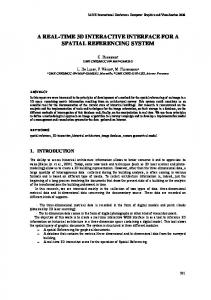
3. SYSTEM OVERVIEW Fig. 1 schematically illustrates our example-based approach for deformation transfer. The main idea of our approach is to create an animation (a deforming model) by reusing the existing data. We transfer the poses and geometry details of source deforming model to the target model first and then adjust the geometry details of the transferred target models by a few user-specified target examples. In our approach, we take a source deforming model, a target model and a small set of target examples as inputs. Our approach consists of three main procedures: deformation transfer, parameterization and retargeting refinement. We briefly describe each procedure in the following. First, the deformations of source model are transferred to the target model [9] (as shown in Fig. 1 (c)). In general, the transferred target models are unnatural or unsmooth due to incorrect transferred deformations or inaccurate correspondences. To refine the transferred results, a parameter space for describing pose space among target models is defined. For an articulated model, it is composed of several meaningful components. Each component can be used to represent a parameter of object. Therefore, we decompose the target model into several near-rigid components by analyzing the deformations among the transferred models (as shown in Fig. 1 (d)). The parameter space is defined by spanning the near-rigid components of the user-specified target key models. Next, the transferred models are parameterized in the parameter space, and then a set of weights relative to each key model is obtained. Then we introduce an example model for each key model and compute detailed refinements between key model and example model. Finally, the transferred model is corrected by combining the weighted blending of these detailed refinements (as shown in Fig. 1 (f)).
Fig. 1. System overview.
HUNG-KUO CHU AND CHAO-HUNG LIN
382
4. DEFORMATION TRANSFER Deformation transfer is to transfer or copy the deformation of a source deforming model to a target model through a correspondence mapping between these two models. In [9], they represent the model deformation as a set of non-translational affine transformations of triangles. Given a reference pose M r and a deformed pose M t of a deforming model, we calculate the deformation gradient of a triangle fit in M t relative to M r as follows. Assuming that the three vertices of fit are v1t, v2t and v3t, we compute the fourth vertex as v4t = v1t + (v2t − v1t ) × (v3t − v1t ) of fit is Qit = Oit (Oir )−1
|(v2t − v1t ) × (v3t − v1t )| . Then the deformation gradient
(1)
where Oti is [v2t − v1t v3t − v1t v4t − v1t ] (similar for Ori). Once the deformation gradients of triangles are obtained, each deformation gradient Q in the deforming model is applied to its corresponding triangle in the target model. In general, the connectivity of the source and target models is not identical. To transfer the deformation gradients, the mapping between these two models must be determined, or even the connectivity of these two models must be identical. In this paper, the 3D fitting approach presented in [9] is adopted. The compatible connectivity and correspondence are obtained by fitting the source model to the target model.
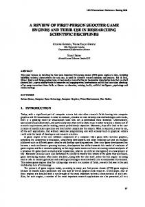
(a) (b) (c) (d) (e) Fig. 2. Some un-natural results of deformation transfer; (a) The reference pose of source model (top) and target model (bottom); (b)-(e) The results of deformation transfer [9].
Note that the deformation transfer technique presented in [9] is designed for the case that there is a clear semantic correspondence between the source and target models. In addition, the selected reference pose of the source deforming model must be very similar to the pose of the target model as mentioned in [14]. However, in our experiments, the results of deformation transfer may still be unnatural even for the case that the source and target models are similar in shape and even pose. It is because that the local detailed deformations of source model are cloned to the target model. It causes that the characteristic deformations of the target model are mixed with those of the source model. Moreover, inaccurate correspondence mapping would affect the qualities of transferred results especially for the regions with larger deformations. To give a better understanding for the description above, we give an example shown in Fig. 2. The source deforming model is a Man model with muscular shape. On the contrary, the target model is a Monkey model without any apparent muscles. The reference pose of the source model is very
EXAMPLE-BASED DEFORMATION TRANSFER FOR 3D POLYGON MODELS
383
similar to the target model as shown in Fig. 2 (a). However, not only the pose but these big muscles of Man model are transferred to the Monkey model (as shown in the Figs. 2 (b) and (c) (the red circles)). In addition, the length of arms of Monkey model is longer than that of Man model. Excessive deformations are transferred to the Monkey model in those parts, causing crossover in the arms (as shown in Fig. 2 (d)). The un-smooth transfer is observed in the regions around the joins (as shown in Fig. 2 (e)) due to the inaccurate correspondence in those regions. To solve the problems mentioned above, we propose a novel example-base deformation transfer approach. We detailly describe our approach in the next section.
5. EXAMPLE-BASED DEFORMATION TRANSFER Inspired by the concepts of example-based facial expression cloning presented in [8], we not only transfer the pose of source mesh to the target model but also preserve the characteristic deformations of target model using a few examples. The used examples (E1 and E2) must be similar to the chosen key models (T1 and Tn) in pose, as showed in Fig. 3. We calculate the triangle deformation gradients (D1 and Dn) between the key models and their corresponding example models using Eq. (1). The deformation gradients (D1 and Dn) represent the detailed refinements between the key models and their corresponding example models. The basic idea of our approach is to calculate the unknown deformation gradients (D2, …, Dn-1) of the transferred models from the known deformation gradients (D1 and Dn) of the example models. Then, apply the obtained deformation gradients to the transferred models to refine (or correct) the transferred results. The refinement process consists of two main steps: parameterization and deformation gradient blending. First, the target model is decomposed into several near-rigid components which is used to define a pose space. The transferred models are parameterized in the pose space (section 5.1), and then blend the deformation gradients of the example models with the obtained weights (coefficients) to regenerate a more natural result of deformation transfer (section 5.2).
Fig. 3. An illustration of the proposed example-based deformation transfer approach.
5.1 Parameterization The purpose of target model parameterization is to parameterize the transferred target models to a pose space consisting of key models. The critical point of the definition of
384
HUNG-KUO CHU AND CHAO-HUNG LIN
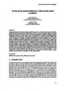
parameter space is how to encode the important shape properties of a 3D model to the parameter components of the parameter space. In [10], they take the degrees of shape protrusion or thickness as the parameter components to distinguish 3D free-form shapes. In [8], the deformation space is spanned by some user-specified feature points on the example models. The facial expressions are distinguished by the positions of feature points. However, these two approaches are not suitable to be applied to the deformation of articulated objects (a common type of 3D models) which usually contain large scale rotations. In this paper, we proposed a novel approach to parameterize the shape properties of articulate models. The basic idea is to decompose the target model, i.e., articulated model, into several near-rigid components, and then relate each near-rigid component to a parameter component of the parameter space. The model decomposition and parameterization approaches are described below. Model Decomposition: Once the poses of source model are transferred to that of target models, these transferred poses are utilized to decompose the target model. We adopt the approach presented in [14] to decompose the target model. The target model is decomposed into several near-rigid patches according to the deformation gradients (calculated by Eq. (1)) computed from various poses of the target model. The boundary candidates of near-rigid patches are defined as the regions with larger deformation distances (or elasticity degrees). The deformation distance is evaluated as the maximal difference in the deformation gradients between two adjacent faces among all poses of target model. Fig. 4 shows an example of the model decomposition. We encode the deformation distances by colors in Fig. 4 (b). It shows that the regions around the joins have comparative larger deformation distances, and therefore the boundaries lie in these regions (as shown in Fig. 4 (c)).
(a) (b) (c) Fig. 4. An example of model decomposition; (a) The transferred poses of target model; (b) The deformation distance coded by color; (c) The decomposed result.
Parameterization: Each near-rigid patch can be regarded as a meaningful component in an articulated model. Therefore, the near-rigid patches are suitable to represent the shape properties. Each decomposed patch is regarded as a solid object. We use the rotation component of the affine transformation of this decomposed patch from the reference pose, i.e., the target model which has been transferred from the reference pose of the source model, to the deformed pose as a parameter component in the parameter space. The rotation component RP between two corresponding solid patches can be calculated by using the following equation:
EXAMPLE-BASED DEFORMATION TRANSFER FOR 3D POLYGON MODELS
min ||(vir × RP + TP ) − vit ||, i = 1 " n pv
385
(3)
RP
where vir and vit represent the vertex of near-rigid patch in the reference model and its corresponding vertex in the deformed model, respectively; npv represents the number of vertices in a patch; TP represents the translation component. The optimization problem in Eq. (3) can be solved using the registration algorithm K presented in [15]. The rotation component RP is represented by a unit quaternion qR in order to efficiently manipulate the rotation transform and define the parameter space. Any G K unit quaternion qR can be described in the standard parameterization qR (θ , nˆ ) = (cos θ /2, 2 nˆ sin θ /2), i.e., a unit 4-tuple vector (q0, q) = (q0 q1 q2 q3), where q0 + q12 + q22 + q32 = 1. In the parameter space construction, we have to calculate the Euclidian distance of the quaternions. Therefore, we set the constraint q0 ≥ 0 to let all quaternions lie in the same (northern) hemisphere. In the implementation, if q0 < 0, the quaternion is multiplied by − 1. Because that the components (q) = (q1 q2 q3) comprise the parameters θ and nˆ. To compact the parameter representation, we encode the characteristic features of patch by only the three components (q1 q2 q3) of quaternion, and therefore the components (q1 q2 q3) are used to represent a patch in the parameter space. For an articulated object, the shapes and poses of near-rigid patches are affected by their neighboring patches. Therefore, a parameter space defined by individual patches may generate unsmooth results. A more appropriate setting is to include the neighboring patches into the parameter representation. Thereby, the parameter representation of patch P is defined as Fp = (qP, qn1, …, qnpn), where qP and qni (1 ≤ i ≤ npn) represent the quaternion components of patch P and its neighboring patches, respectively; npn represent the number of neighboring patches. The characteristic features of a target model are represented as a collection of quaternion components, called feature vector F. Note that the maximal number of neighboring patches in an articulated object is 4. Therefore, npn is set to 4 in our implementation. If the number of neighboring patches is less than the defined value, we simply fill the null entities of feature vector with 0. Inspired by the approach presented in [8], we adopt the radial basis function with these obtained feature vectors of example models to define the parameter space of target model. The coefficients of a transferred target model T in the parameter space are defined as: ne
y (T ) = ∑ wiφi (||F(T ) − F(Ti )||),
(4)
i =1
where Ti represents the key model; ne represents the number of key models; φi() and wi is the radial basis function and its corresponding radial coefficient for key model Ti, respectively. The radial basis function φ() is a function of distance between the feature vector of transferred model F(T) and the feature vector of key model F(Ti). The radial basis function is defined as a Gaussian function (as shown in Eq. (5)) to generate a smooth parameter space.
φ (d ) = exp(− β d 2 ), β > 0
(5)
HUNG-KUO CHU AND CHAO-HUNG LIN
386
5.2 Blending Once the weights are obtained, the detailed refinements {D2 … Dn-1} for the transferred models {T2 … Tn-1} can be obtained by blending the detailed refinements of key models relative to examples (D1 and Dn) with the obtained weights as follows: ne
Di = ∑ wi , j D j , 1 ≥ i ≥ n p
(6)
j =1
where np represents the number of transferred target models. It is well known that the linear blending of affine transformation matrixes will result in unnatural effects [16]. Therefore, we adopt polar decomposition approach to decompose the deformation gradient into shear/scale S and rotation R components, that is Di = RiSi, 1 ≥ i ≥ np.
(7)
Next, the exponential mapping approach is adopted to individually blend the rotation component in so Eq. (3) using the obtained weights and the shear/scale matrix is blended linearly, that is ⎛ ne ⎞ ne Di = exp ⎜ ∑ wi , j log R j ⎟ × ∑ wi , j S j , 1 ≥ i ≥ n p . ⎜ j =1 ⎟ j =1 ⎝ ⎠
(8)
The non-translational affine transformation for each patch in the refined target model is computed individually. Thereby, we need to reconstruct the entire model from the decomposed patches. As like [9], in order to ensure that the non-translational affine transformations for patches are consistent, the shared vertices in the adjacent patches are required to be transformed to the same place. This consistency requirement can be archived by solving the following constrained optimization equation. n pn
min
v�1 " v�n
∑ ||Q sj − Qtj ||2
(9)
j =1
subject to Tjvi + dj = Tkvi + dk, ∀i, ∀j, k ∈ p(vi) where Qs and Qt represent the patch deformations in the transferred model and the refined model, respectively; p(vi) is the set of all patches that share vertex vi; npn represents the number of patches in the target model.
6. EXPERIMENTAL RESULTS To demonstrate the feasibility of our approach, four animation sequences are tested. The test data are evaluated on a PC with an Intel Pentium 4 2.4GHz CPU and 1GB memory. Our approach takes about 4 ~ 9 seconds to transfer 1 frame. The pleasing deformation transfer results generated by our approach are shown in Figs. 5 and 6. To give a
EXAMPLE-BASED DEFORMATION TRANSFER FOR 3D POLYGON MODELS
387
Fig. 5. Transfer a standing sequence of a leopard model to a dog model. 1st row: the source models; 2nd ~ 4th rows: the results generated by [9], [8] and our approach, respectively (the poses in the red rectangles are the user-specified examples).
Fig. 6. Transfer a swimming sequence of a male model to a monkey model. 1st row: the source models; 2nd ~ 4th rows: the results generated by [9], [8] and our approach, respectively (the poses in the red rectangles are the user-specified examples).
comparison, we also show the deformation transfer results generated by the state-of-the-art approaches [8] and [9]. Only some key poses of the animation are shown in the figures. As for the entire transferred animation sequences, please refer to our accompanying video (http://140.116.80.112/Deformation Transfer/MRE_Video.avi). In all experiments, only 2 ~ 4 examples are used. In [9], the deformation transfer results could be unnatural (as shown in Fig. 7) when the source and target models are different in anatomical structure. The detailed deformations or excessive local deformations of source model are transferred to the target model. In our approach, we can obtain more natural results with the aid of example models. Another problem of deformation transfer is that the unsmooth effects caused by the inaccurate correspondence are magnified in the regions with larger deformations (as shown in Fig. 8). Even though the excellent fitting approach [9] is adopted, we cannot guarantee
388
HUNG-KUO CHU AND CHAO-HUNG LIN
(a) (b) (c) (d) (e) (f) Fig. 7. (a), (d) The source models; (b), (e) The deformation transfer results generated by [9]; (c), (f) Our approach.
(a) (b) (c) Fig. 8. (a) The source model; (b) The deformation transfer results generated by [9]; (c) Our approach.
(a) (b) (c) (d) (e) (f) Fig. 9. (a), (d) The source models; (b), (e) The deformation transfer results generated by [8]; (c), (f) Our approach.
that an accurate correspondence is obtained. With the aid of example models, our approach has the ability of eliminating unsmooth effects. In [8], the displacement vector cannot correctly express the large scale rotations. Therefore, the shrinking problem might be happened (as shown in Fig. 9). In our approach, the shrinking problem can be avoided by non-linearly blending the rotation. In our approach, the poses and geometry details of source deformation models are transferred to the target model and the geometry details of the transferred target models are then adjusted by the user-specified examples. Therefore, the worst result of our approach is the transferred target model (without any detail adjustment). If the examples are not well-chosen, i.e., the deformation space spanned by the examples does not com-
EXAMPLE-BASED DEFORMATION TRANSFER FOR 3D POLYGON MODELS
389
prise the poses of the transferred target models, some geometry details could not be welladjusted. However, it is still better than the transferred target models.
7. CONCLUSION We presented a novel example-based approach for deformation transfer of 3D polygon model. The deformations are transferred from the source deforming model to the target model while the abnormal details caused by incorrect transferred details or inaccurate correspondence are corrected by a few of target examples. The experiment results show that our approach can generate natural and convincing deformation transfer results even for the case that the source and target models are very differences in details.
REFERENCES 1. M. Gleicher, “Retargetting motion to new characters,” ACM Transactions on Graphics, 1998, pp. 33-42. 2. I. Baran and J. Popović, “Automatic rigging and animation of 3D characters,” ACM Transactions on Graphics, Vol. 26, 2007, pp. 72-1-72-8. 3. C. Rose, M. F. Cohen, and B. Bodenheimer, “Verbs and adverbs: Multidimensional motion interpolation,” IEEE Computer Graphics and Applications, Vol. 18, 1998, pp. 32-40. 4. Y. Li, T. Wang, and H. Y. Shum, “Motion texture: A two-level statistical model for character synthesis,” ACM Transactions on Graphics, 2002, pp. 465-472. 5. S. I. Park, H. J. Shin, and S. Y. Shin, “On-line locomotion generation based on motion blending,” ACM Transactions on Graphics, 2002, pp. 105-111. 6. L. Kovar, M. Gleicher, and F. Pighin, “Motion graphs,” ACM Transactions on Graphics, 2002, pp. 473-482. 7. J. Y. Noh and U. Neumann, “Expression cloning,” ACM Transactions on Graphics, 2001, pp. 277-288. 8. H. Pyun, Y. Kim, W. Chae, H. Kang, and S. Y. Shin, “An example based approach for facial expression cloning,” in Proceedings of ACM SIGGRAPH/EUROGRAPHICS Symposium on Computer Animation, 2003, pp. 167-176. 9. R. W. Sumner and J. Popović, “Deformation transfer for triangle meshes,” ACM Transactions on Graphics, Vol. 23, 2004, pp. 399-405. 10. P. P. Sloan, C. F. Rose, and M. F. Cohen, “Shape by example,” in Proceedings of Symposium on Interactive 3D Graphics, 2001, pp. 135-144. 11. R. Heck and M. Gleicher, “Parametric motion graphs,” in Proceedings of Symposium on Interactive 3D Graphics and Games, 2007, pp. 129-136. 12. R. W. Sumner, M. Zwicker, C. Gotsman, and J. Popović, “Mesh-based inverse kinematics,” ACM Transactions on Graphics, Vol. 24, 2005, pp. 488-495. 13. K. G. Der, R. W. Sumner, and J. Popović, “Inverse kinematics for reduced deformable models,” ACM Transactions on Graphics, Vol. 25, 2006, pp. 1174-1179. 14. T. Y. Lee, Y. S. Wang, and T. G. Chen, “Segmenting a deforming mesh into nearrigid components,” Pacific Graphics, Vol. 22, 2006, pp. 729-739. 15. P. J. Besl and N. D. McKay, “A method for registration of 3-D shape,” IEEE Trans-
390
HUNG-KUO CHU AND CHAO-HUNG LIN
actions on Pattern Analysis and Machine, Vol. 14, 1992, pp. 239-256. 16. K. Shoemake and T. Duff, “Matrix animation and polar decomposition,” in Proceedings of the Conference on Graphics Interface, 1992, pp. 259-264. 17. Y. T. Chang, B. Y. Chen, W. C. Luo, and J. B. Huang, “Skeleton-driven animation transfer based on consistent volume parameterization,” in Proceedings of Computer Graphics International Conference, 2006, pp. 78-89. 18. W. W. Feng, B. U. Kim, and Y. Yu, “Real-time data-driven deformation using kernel canonical correlation analysis,” ACM Transactions on Graphics, Vol. 27, 2008, pp. 19.1-19.10. 19. Kircher and M. Garland, “Editing arbitrarily deforming surface animations,” ACM Transactions on Graphics, Vol. 25, 2006, pp. 1098-1107. 20. Y. S. Wang and T. Y. Lee, “Example-driven animation synthesis,” The Visual Computer, Vol. 24, 2008, pp. 765-773. 21. H. K. Chu and T. Y. Lee, “Multi-resolution mean shift clustering algorithm for shape interpolation,” IEEE Transactions on Visualization and Computer Graphics, Vol. 15, 2009, pp. 853-866. 22. C. H. Lin, T. Y. Lee, H. K. Chu, and C. Y. Yao, “Progressive mesh metamorphosis,” Journal of Computer Animation and Virtual Worlds, Vol. 16, 2005, pp. 487-498. 23. C. H. Lin and T. Y. Lee, “Metamorphosis of 3D polyhedral models using progressive connectivity transformations,” IEEE Transactions on Visualization and Computer Graphics, Vol. 11, 2005, pp. 2-12. 24. T. Y. Lee and P. H. Huang, “Fast and institutive polyhedral morphing using SMCC mesh merging scheme,” IEEE Transactions on Visualization and Computer Graphics, Vol. 9, 2003, pp. 85-98. 25. T. Y. Lee, C. Y. Yao, H. K. Chu, M. J. Tai, and C. C. Chen, “Generating genus-n-tom mesh morphing using spherical parameterization,” Computer Animation and Virtual Worlds, Vol. 17, 2006, pp. 433-443. 26. T. Y. Lee, C. H. Lin, H. K. Chu, Y. S. Wang, S. W. Yen, and C. R. Tsai, “Mesh pose-editing using example,” Journal of Computer Animation and Virtual Worlds, Vol. 18, 2007, pp. 235-245.
Hung-Kuo Chu (朱宏國) received the B.S. degree in Computer Science and Information Engineering from National Cheng Kung University, Tainan, Taiwan, in 2003. Now, he is pursuing his Ph.D. degree at Department of Computer Science and Information Engineering, National Cheng Kung University. His research interests include computer graphics.
EXAMPLE-BASED DEFORMATION TRANSFER FOR 3D POLYGON MODELS
391
Chao-Hung Lin (林昭宏) was born in Koushung, Taiwan, R.O.C., in 1973. HE received his B.S in Computer Science and Information Engineering from Fu Jen Catholic University, M.S. and Ph.D. in Computer Science and Information Engineering from National Cheng Kung University, Taiwan in 1997, 1998 and 2004, respectively. Now, he is an Assistant Professor in the department of Geomatics at National Cheng Kung University in Tainan, Taiwan. His current research interests include digital tourist map generation, digital point cloud processing, information visualization, computer graphics and image processing.