the creation of a single character pose a relatively simple task, but creating mesh animations is ... as an important problem. Deformation transfer [Sumner and Popovic 2004] provides one pos- ..... tation, it is quite fast. The flamingo is the largest ...
Semantic Deformation Transfer Ilya Baran1 1
Daniel Vlasic1
Computer Science and Artificial Intelligence Laboratory Massachusetts Institute of Technology
Eitan Grinspun3
Jovan Popovi´c1,2,4
2
Advanced Technology Labs Adobe Systems Incorporated
3
4
Columbia University University of Washington
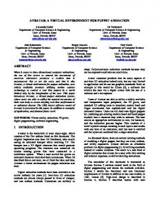
Figure 1: Semantic deformation transfer learns a correspondence between poses of two characters from example meshes and synthesizes new poses of the target character from poses of the source character. In this example, given five corresponding poses of two characters (left), our system creates new poses of the bottom character (right) from four poses of the top character.
Abstract
1 Introduction
Transferring existing mesh deformation from one character to another is a simple way to accelerate the laborious process of mesh animation. In many cases, it is useful to preserve the semantic characteristics of the motion instead of its literal deformation. For example, when applying the walking motion of a human to a flamingo, the knees should bend in the opposite direction. Semantic deformation transfer accomplishes this task with a shape space that enables interpolation and projection with standard linear algebra. Given several example mesh pairs, semantic deformation transfer infers a correspondence between the shape spaces of the two characters. This enables automatic transfer of new poses and animations.
Advancements in modeling, deformation, and rigging have made the creation of a single character pose a relatively simple task, but creating mesh animations is still time-consuming and laborious. At the same time, recent progress in mesh-based performance capture and deformation transfer has led to an increasing number of available animations. As a result, reusing mesh animation is emerging as an important problem.
CR Categories: I.3.5 [Computer Graphics]: Computational Geometry and Object Modeling—Hierarchy and geometric transformations I.3.7 [Computer Graphics]: Three Dimensional Graphics and Realism—Animation Keywords: Deformation, rigging, animation
Deformation transfer [Sumner and Popovi´c 2004] provides one possible solution. Given a correspondence between two meshes, it copies the deformations of the triangles of the first mesh onto those of the second. The key assumption is that the correspondence is literal: matched parts of the meshes move in geometrically identical ways. Although deformation transfer works well for similar characters and is able to transfer subtle motion details, semantic correspondence is often desirable. The distinction between literal and semantic correspondence can be illustrated with an example of two mesh characters, Alex and Bob. If Alex is walking normally and Bob is walking on his hands, literal correspondence maps Alex’s legs to Bob’s legs and Alex’s arms to Bob’s arms, while semantic correspondence maps Alex’s legs to Bob’s arms and, possibly, vice versa (see Figure 1). The ability to transfer motion with semantic correspondence expands the range of potential applications, enabling transfer to drastically different characters that move in unique ways. Some existing methods could be adapted to transfer motion with semantic correspondence, but with drawbacks. If it is possible to find a geometrically corresponding set of end effectors, their motions can be retargeted [Gleicher 1998] and the rest of the mesh could be inferred with MeshIK [Sumner et al. 2005]. Alternatively, if the motions are primarily skeletal, the user can build a skinning model for the target mesh and use a skeletal retargetting
Source shape space
Csrc Csrc Project
Input pose
Source examples Weights: (0.7, 0.3) Interpolate
Ctgt Target examples
Ctgt−1 Target shape space
Output pose
Figure 2: Semantic deformation transfer maps the input pose into the source shape space, projects it onto the affine span of example poses, uses the obtained weights to interpolate target example poses in the target shape space, and reconstructs the target pose. method [Dontcheva et al. 2003; Hsu et al. 2004]. Both solutions complicate workflow and impose undesirable constraints on the types of transfer that can take place and on the information that the user has to provide. Properly retargetting end effectors requires adjusting the entire time curve, while a skeletal model may not be able to capture the full subtlety of the poses. Semantic deformation transfer allows the user to specify semantic correspondence (instead of a literal mesh correspondence) by providing examples of corresponding poses of Alex and Bob. To infer the correspondence between two characters and map new poses of one onto the other, semantic deformation transfer represents each pose as a point in a high-dimensional Euclidean “shape space,” enabling the use of standard linear algebra tools. Using the example poses, semantic deformation transfer constructs a linear map from the source to the target shape space. Given a new source pose, semantic deformation transfer encodes it into the source shape space, maps it to the target shape space, and reconstructs the result to obtain a corresponding target pose (see Figure 2). For semantic deformation transfer to work, the shape space must satisfy two requirements: linear interpolation between points in the shape space must produce blended poses without artifacts, and projection of a pose onto a subspace of the shape space must produce the most similar pose in the subspace to the original. We provide a shape space that meets these requirements.
2
Shape Space
The proper choice of the shape space is critical for semantic deformation transfer. Several existing mesh representations [Sumner et al. 2005; Lipman et al. 2005; Kircher and Garland 2008] come close to satisfying this requirement and we combine them into a hybrid representation that enables semantic deformation transfer.
2.1 Transfer A shape space for a particular mesh connectivity is defined by an encoding map C: R3n → Rm that takes mesh vertex positions and outputs a coordinate vector, and by a reconstruction map C −1 that
Figure 3: The rest pose from Figure 1 is corrupted by a small amount of high frequency noise (left). Projecting it to the subspace spanned by the five training poses in Figure 1 recovers the pose, if the projection is done in the space of deformation gradient coordinates, or our patch-based LRI coordinates, but not in linear rotation-invariant coordinates. This projection error causes shaking artifacts when transferring from an imperfect source motion using LRI coordinates. returns vertex positions from a coordinate vector. The reconstruction of an encoding must return the original vertex positions (but we do not require multiple encodings to have distinct reconstructions). Semantic deformation transfer relies on two basic operations in the shape space Rm : 1. Interpolation: Given p example p and p P poses x1 , . . . , xP weights w1 , . . . , wp such that i wi = 1, compute i wi xi , the affine combination of the poses. 2. Projection: Given p example poses x1 , . . . , xp and another pose q, compute p weights w1 , . . . , wp that minimize ° ° p ° ° X X ° ° q − w x subject to wi = 1. ° i i° ° ° i=1
i
Letting the cross denote the pseudoinverse, the solution is: w2 . † .. = [x2 − x1 x3 − x1 . . . xp − x1 ] [q − x1 ], wp P and w1 = 1 − pi=2 wi . We focus on affine rather than linear interpolation and projection because the origin of the shape space has no special meaning for the transfer. A shape space is suitable for interpolation if affine combinations of several poses do not result in shrinking or other artifacts (at least when the coefficients are not too negative). Suitability for projection means that the projection of a pose onto an affine span of other poses must retain the characteristics of the unprojected pose as much as possible. For example, random high-frequency noise must be nearly orthogonal to meaningful pose changes (see Figure 3) and deformations in different parts of the mesh should be nearly orthogonal to each other (see Figure 5). A shape space that supports interpolation and projection enables semantic deformation transfer with the following simple algorithm (Figure 2): 1. Given p pairs of example poses, encode them into the source and target shape spaces using Csrc and Ctgt . Precompute the pseudoinverse (using singular value decomposition) for projection in the source space.
Figure 4: Interpolating halfway between two “poses” of this cone, P 1 and P 2, fails with deformation gradient coordinates, but works with patch-based LRI coordinates. 2. Given a new source pose, encode it into the source shape space and use projection to express it as an affine combination of the source example poses with weights w1 , . . . , wp . 3. Use these weights to interpolate the corresponding target ex−1 ample poses in their shape space and use Ctgt to reconstruct the resulting pose. Together, the projection and interpolation comprise a linear map from the source shape space to the target shape space. The above method transfers the aspects of the pose spanned by the example poses. However, global rotation and translation often depend on the pose in a complicated way (e.g. through foot plants or dynamics), and the above method does not take this into account. We therefore ignore the reconstructed global orientation and use heuristics for some of our animations: we apply the average rotation from the source to the target directly and obtain the translation by treating the lowest vertex of the output motion as a foot plant.
2.2
Existing Shape Representations
In choosing the shape space, an obvious possibility is to use the vertex positions (C is the identity map). This is known to work poorly for interpolation because linearly blending between rotated parts of the mesh does not interpolate rotation and causes shrinking and other artifacts. The inadequacy of vertex positions has led to the development of many mesh representations [Botsch and Sorkine 2008]. Linear mesh representations (C is a linear map), such as Laplacian coordinates, are also unsuitable for interpolation because they produce the same artifacts as vertex positions: an affine combination in such a space is equivalent to the same affine combination in the vertex position space. An approach that produces excellent interpolation results is to define a Riemannian metric (instead of the Euclidean metric) on the vertex position space that penalizes non-isometric deformation [Kilian et al. 2007]. However, computation in this space is much more difficult and expensive than in a Euclidean space. Deformation Gradients One approach to handling rotations is to represent a mesh using deformation gradients to encode individual face transformations. Given two poses, the deformation gradient of a mesh face is the matrix that transforms the edge and normal vectors of the face from the first pose to the second. Since translation does not affect the edge and normal vectors, translations are not recorded in the deformation gradient. Let v1 , v2 , v3 be the three vertices of a face and let n be its scaled normal, computed using p n = (v2 − v1 ) × (v3 − v1 )/ k(v2 − v1 ) × (v3 − v1 )k, following Sumner and Popovi´c [2004]. Let v ˜1 , v ˜2 , v ˜3 , and n ˜ be the corresponding vertices and scaled normal in the rest pose. The
Figure 5: The span of the poses P 1 and P 2 on the left defines the configuration space of the character’s left knee. If we take a pose (middle) and project it onto this subspace, we should recover the knee configuration. The global rotation throws deformation gradient coordinates off (right), while projecting in patch-based LRI coordinates correctly recovers the bent knee. deformation gradient is the following 3 × 3 matrix: D = [v2 − v1
v3 − v1
n] [˜ v2 − v ˜1
v ˜3 − v ˜1
n ˜ ]−1 .
A mesh can be represented by recording the deformation gradients of all of the faces relative to a rest pose. For example, MeshIK uses such a representation for projection [Sumner et al. 2005]. However, linearly interpolating deformation gradients does not preserve rotations. Therefore, for interpolation, MeshIK performs a polar decomposition of each deformation gradient QS = D and stores S and log Q separately, allowing rotations to be interpolated in logarithmic space. This representation becomes problematic when the mesh undergoes a large global rotation relative to the rest pose (imagine interpolating the rest pose and a perturbed rest pose rotated 180 degrees: each face rotation would choose a different interpolation path, depending on its perturbation). Factoring out the average deformation gradient rotation (found by using polar decomposition to project P Qf to a rotation matrix) and storing it separately avoids f ∈faces this problem. We refer to this representation as deformation gradient coordinates. Even with the global rotation factored out, this representation has two more drawbacks. For interpolation, factoring out the average rotation may not be enough and interpolating between two poses in which some faces have rotated more than 180 degrees will result in discontinuity artifacts (Figure 4). These types of artifacts can often arise in deformations of tails, snakes, and tentacles, for example. For projection, the deformation gradient coordinates are not locally rotation invariant, resulting in dependency between degrees of freedom that should be independent. Figure 5 shows an experiment in which we project a pose with a bent back and a bent knee onto the subspace of poses spanning possible knee configurations. In deformation gradient coordinates, the dependence between the bent back and bent knee results in an incorrect projection. Rotation-Invariant Coordinates Linear rotation-invariant (LRI) coordinates [Lipman et al. 2005] define a coordinate frame at each mesh vertex and encode that vertex’s one-neighborhood in essentially cylindrical coordinates in that frame. Because the coordinate frames themselves are not stored, this representation is rotation-invariant. The mesh is efficiently reconstructed by first finding connection maps that encode relationships between frames. A connection map is a rotation matrix that represents a frame in the coordinates of an adjacent frame. Using the connection maps, the reconstruction algorithm solves a large least-squares
2.3 Patch-Based LRI Coordinates To define our patch-based LRI coordinates, we extend LRI by partitioning the mesh faces into several contiguous disjoint patches, factoring out the average rotations of these patches, and using these average rotations as frames. This extension requires some care: • Extending cylindrical coordinates to larger patches directly does not work because deformations of larger patches are likely to have faces that rotate relative to the patch frame. As with Cartesian coordinates, linearly interpolating between rotated triangles in cylindrical coordinates does not (in general) interpolate the rotation. We therefore encode the local geometry of the larger patches using polar decompositions of deformation gradients. • LRI reconstructs connection maps between frames from overlapping vertex neighborhoods. Using overlapping patches would make reconstruction more expensive: to solve for the patch frames, we would first need to reconstruct the individual patches from local deformation gradients and then reconstruct the entire model from deformation gradients again (so as not to have seams). Instead, like Kircher and Garland [2008], we store the connection maps explicitly, but unlike them, we use orthonormal frames because this avoids global shear artifacts in reconstruction that our experiments revealed (see video). • We encode rotations with matrix logarithms. Compared to the nonlinear quaternion interpolation, linearly blending matrix logarithms is not rotation-invariant and introduces error. Because this interpolation error is smallest when rotations are small or coaxial, we use deformation gradients relative to a rest pose. For the same reason, unlike LRI, we work with patch frames relative to the rest pose. As a result, when we encode the rest pose, all of our connection maps are the identity. Our experiments confirmed that the results are not sensitive to the choice of the rest pose, as long as it is a reasonable pose for the character. Encoding Let Df be the deformation gradient of mesh face f relative to the rest pose and let Qf Sf = Df be the polar decom¯ be the average of all position of this deformation gradient. P Let Q Qf ’s (computed by orthonormalizing f Qf using polar decomposition). Let P1 , . . . , Pk be the patches and let p(f ) be the index of the patch to which face f belongs. Let G1 , . . . , Gk be the average rotations of the deformation gradients in each patch. We encode
D1
S1 S2 S3 S4
Patch 1
Current pose
D2 D3 D4
Vertex mean
G−1 2 G1
Q1 Q2 Q3 Q4
mean mean mean
v ¯ ¯ Q
Polar decomposition
G1 G2
Relative face rotations
The sole reliance on local orientation relationships makes LRI coordinates noise-sensitive for projection, as shown in Figure 3. For semantic deformation transfer, this leads to noticeable shaking artifacts, exaggerating imperfections in the input motion (see the accompanying video). We address this problem by defining frames on mesh patches larger than just one-neighborhoods of vertices. In addition to making LRI robust to noise, using larger patches speeds up reconstruction because a much smaller system needs to be factored for each pose.
Rest pose
Patch 2
system to reconstruct the absolute frame orientations, and then solves another least squares system to reconstruct vertex positions. Kircher and Garland’s relative blending [2008] is similar, but frames are non-orthonormal, defined on mesh faces instead of vertices and the connection maps are stored explicitly, rather than encoded in one-neighborhoods. Pyramid coordinates [Sheffer and Kraevoy 2004] also store local geometry in a rotation-invariant manner, but the reconstruction is nonlinear and thus more costly. LRI coordinates work very well for interpolation (as they were designed with that purpose in mind) and we use them as a starting point to construct our shape space.
G1,2 G−1 1 Q1 G−1 1 Q2 G−1 2 Q3 G−1 2 Q4
Figure 6: A mesh with four faces and two patches is encoded into patch-based LRI coordinates. The rotation matrices are stored as logarithms (i.e. as a vector whose direction is the axis of rotation and whose magnitude is the angle.) into patch-based LRI coordinates by storing the following in a coordinate vector (Figure 6): • the scale/shear components: Sf for each face, ¯ • the mean vertex position v ¯, and the mean face rotation log Q, • connection maps between patches: log (Gi,j ) for each pair (i, j) of adjacent patches, where Gi,j = (Gj )−1 Gi , ¡ ¢ • rotations within patches: log (Gp(f ) )−1 Qf for each face. Reconstruction Given such a coordinate vector, we reconstruct the vertex positions using the following algorithm: 1. We first reconstruct each patch’s average rotation. To have rotation-invariance, we only store the relative rotations Gi,j between patches, so reconstruction finds G1 , . . . , Gk that minimize X kGi − Gj Gi,j k2 . {(i,j)|Pi and Pj adjacent}
Because the Gj ’s are 3-by-3 matrices, this can be converted into a linear least squares system and solved using sparse Cholesky factorization. To make the system well-posed, we select an arbitrary Gi and constrain it to the identity matrix. Although the system needs to be refactored for every pose, it is small (its size depends only on the number of patches) and this solve is not a bottleneck in the reconstruction. The resulting matrices may not be orthonormal, so at the conclusion of the least-squares solve we use the polar decomposition to project each Gi to the nearest rotation matrix. 2. Next, we reconstruct the deformation gradient for each mesh face: Df = Qf Sf . The matrix Sf is read directly from the coordinate vector and Qf is computed by multiplying the average patch rotation Gp(f ) found in step 1 by the relative rotation of the face within the patch. 3. The deformation gradients do not give us absolute vertex positions, but applying a deformation gradient to an edge vector of the rest pose gives a desired edge vector for the current pose. To reconstruct the vertex positions v0 (with arbitrary global
translation and rotation), we therefore perform a least squares solve, similar to Kircher and Garland [2008]. For each face f with corners i1 , i2 , i3 , we find v10 , . . . , vn0 that minimize 3 XX f
(vi0 j+1 − vi0 j − Df (˜ vij+1 − v ˜ij ))2 ,
j=1
where v ˜ are the rest pose vertex positions and j + 1 is taken modulo 3. To make this system well-posed, we constrain an arbitrary vertex to the origin. This system can be factored once for a given mesh connectivity using a sparse Cholesky solver and each new pose requires only a back-substitution. 4. We now have a set of vertex positions, but their global position and orientation is arbitrary. We rigidly transform the vertices: ¯ Q ¯ 0 )−1 (v0 − v v = Q( ¯0 ) + v ¯, where v0 is the vertex reconstructed in step 3, v ¯0 is the average 0 ¯ reconstructed vertex position, Q is the average reconstructed ¯ are the desired global position face orientation, and v ¯ and Q and orientation stored in the coordinate vector. Weights Different elements of the coordinate vector have different scales and we therefore multiply the elements by different weights when encoding (and divide during reconstruction). The relative weights of individual coordinates do not affect interpolation, but need to be chosen properly for the projection to work well. The weight on the global motion is nearly zero because our transfer model does not take global motion into account. The weight of each face rotation within itsppatch is set to 1. The weight of the relative rotation log Gi,j is 4 |Pi ||Pj |, where |Pi | is the number of faces in patch i (we use the fourth root because the l2 norm squares the weights). We set a small weight, 0.1, on the scale components because we primarily consider rotation to be a good descriptor of pose. These weights help preserve large-scale shape changes in favor of smaller-scale ones. In principle, we could have individual face weights depending on the face area, but our meshes are relatively uniformly sampled and this has not been necessary. Partition Two considerations apply when partitioning the mesh into patches. Too many small patches tends to result in shaking artifacts, similar to LRI. On the other hand, a patch that is too large can contain faces rotated by more than 180◦ relative to the patch frame, leading to artifacts like those for deformation gradient coordinates (see Figure 4). A conservative prediction of the range of poses minimizes the risk of these artifacts, although they might still occur. Segmenting a human into five to 50 patches works well in our tests. To partition the mesh into patches, we apply the first stage of the reduced deformable model construction algorithm by Wang and colleagues [2007] to our example poses. It starts with each face being a separate patch and merges patches in a bottom-up fashion, while minimizing the error of assuming all faces of a patch deform the same way. We set the error tolerance very high to obtain between five and fifteen patches for each model. Figure 7 shows a partition of one of our test characters.
3
Specifying Semantic Correspondence
Combining Existing Poses We assume that the user has some poses of the source and target characters, but not necessarily enough corresponding pose pairs to properly define a semantic correpondence. Our user interface provides a tool to generate new poses, to be used as examples, by combining elements of existing ones. For example, given a pose with a bent knee and a pose with a straight
Figure 7: For processing the gallop with patch-based LRI coordinates, we split the horse mesh into ten patches. leg, the user can select the knee region and apply the bent knee to the straight leg pose. We accomplish this by transferring the relevant LRI coordinates [Lipman et al. 2005]. The user can select a region of the mesh in one pose, which determines a subset of LRI coordinates (associated with the selected vertices). The user can then apply the shape of that region to another pose. The user can either copy the selected region as-is, or use interpolation/extrapolation to fine-tune its shape. Extracting Source Poses The key to successful semantic deformation transfer is for the set of example poses of the source character to span the relevant aspects of the motion. We can provide the user with such a set from the motion automatically by finding frames that are farthest from each other. Let Vi be the vertex positions of the source mesh in i = 1 . . . p example poses. We start with a rest pose V1 . We set V2 to be the frame of the motion farthest from V1 , and in general Vi to be the frame farthest from the subspace spanned by V1 through Vi−1 . All distances are measured in the shape space of patch-based LRI coordinates. This leaves it to the user to specify only the target’s corresponding poses. Splitting Independent Parts In many cases, the user can reduce the amount of work to construct example poses by decomposing a semantic correspondence into correspondences between independent parts of the meshes. For example, for transfering Alex’s normal walk to Bob’s walk on his hands, the mapping of Alex’s upper body to Bob’s lower body can be specified independently from the mapping of Alex’s lower body to Bob’s upper body. When the user specifies such a decomposition on Alex, our prototype UI extracts Alex’s upper body motion separately from his lower body motion (using LRI coordinates from the rest pose to keep the remainder of Alex fixed). It then uses the procedure in the previous paragraph to extract representative poses from both the upper body and the lower body motions. The result is that half of the poses need only the upper body posed and half of the poses only need the lower body posed.
4 Results We applied our method to publicly available mesh animations from performance capture [Vlasic et al. 2008] and deformation transfer [Sumner and Popovi´c 2004]. The motions we created (available in the accompanying video) are listed in Table 1. Although we did not spend much time optimizing our implementation, it is quite fast. The flamingo is the largest mesh we tested at 52,895 triangles. Encoding a frame of the flamingo into patchbased LRI coordinates takes 0.22 seconds and reconstruction takes 0.25 seconds on a 1.73 Ghz Core Duo laptop. Given the example poses, applying semantic deformation transfer to the 175 frame crane animation takes 136 seconds, including reading the data from
Source motion Crane Swing Alex March Bob March Gallop Squat
Target character Flamingo Hand Handstand Xavier Alex and Bob Cone
Example poses 7 12 5 7 8 and 6 2
Table 1: Generated results (the number of example poses includes the rest pose). disk, partitioning both meshes into patches, building the linear map, applying it, and reconstructing.
5
Discussion and Conclusion
With semantic deformation transfer we obtained a variety of useful results in an intuitive manner (Figure 8). The ability to treat a pose as a point in Euclidean space enables the use of tools from linear algebra and simplifies processing. Our simple transfer model, while adequate for many motions, is incapable of representing nonlinear requirements (e.g. the target knee should only bend when the source knee is bent more than 45 degrees). A more sophisticated model, such as radial basis functions, could handle a wider range of transfers. Our shape space makes it possible to explore these directions. Although projection in our shape space produces intuitive results, we do not know whether distance in the shape space is a good measure of pose dissimilarity, or, indeed how to measure pose dissimilarity at all. Formulating such a metric would enable a quantitative comparison of different shape spaces and provide a principled way of choosing weights for our coordinates. Given the patch-based nature of our shape space representation, one might expect to see seam artifacts between patches. A seam artifact appears when the interpolated rotation of a face differs significantly depending on the patch to which it is assigned. This difference results from the inconsistency between logarithmic blending of connection maps and face rotations relative to the frame. This inconsistency tends to be small and is masked somewhat by the least squares vertex reconstruction step, so the effects are not visible in any of our examples. We constructed synthetic deformations of a cone in which faces rotate along different axes from the rest of the patch and were able to get slight seam artifacts to appear when blending with patch-based LRI coordinates . Should seam artifacts appear in a real motion, they could be eliminated by making the partition into patches ”soft.” Determining the minimum amount of information necessary to specify a transfer is an interesting conceptual and practical challenge: while a surface correspondence enables literal deformation transfer and a few example poses enable semantic deformation transfer, can we perform semantic motion transfer using example motion clips? Different characters move with different rhythms in a way that is difficult to capture with just a mapping between their pose spaces. Building a model that takes time or even physics into account could lead to much higher quality automatically generated animations than what is currently possible.
6 Acknowledgments We thank the anonymous reviewers for helpful comments that greatly improved the exposition. Wojciech Matusik helped us set the early course on exploring geometric representations for moving meshes. Robert Wang and Yeuhi Abe provided valuable feedback and editing. Thanks to Tom Buehler for help with the video and to
Figure 8: A dancer’s pose is mapped to a large hand and a man’s pose to a flamingo. Emily Whiting for narrating it. This work was supported in part by the NSF (MSPA Award No. IIS-05-28402, CSR Award No. CNS-06-14770, CAREER Award No. CCF-06-43268, grant No. CCF-0541227). This work was also supported by grants from the Singapore-MIT Gambit Game Lab, Adobe Systems, Pixar Animation Studios and by software donations from Autodesk and Adobe Systems.
References B OTSCH , M., AND S ORKINE , O. 2008. On linear variational surface deformation methods. IEEE Transactions on Visualization and Computer Graphics 14, 1, 213–230. D ONTCHEVA , M., Y NGVE , G., AND P OPOVI C´ , Z. 2003. Layered acting for character animation. ACM Transactions on Graphics 22, 3 (July), 409–416. G LEICHER , M. 1998. Retargetting motion to new characters. In Proceedings of SIGGRAPH 98, Computer Graphics Proceedings, Annual Conference Series, 33–42. H SU , E., G ENTRY, S., AND P OPOVI C´ , J. 2004. Example-based control of human motion. In 2004 ACM SIGGRAPH / Eurographics Symposium on Computer Animation, 69–77. K ILIAN , M., M ITRA , N. J., AND P OTTMANN , H. 2007. Geometric modeling in shape space. ACM Transactions on Graphics 26, 3 (July), 64:1–64:8. K IRCHER , S., AND G ARLAND , M. 2008. Free-form motion processing. ACM Transactions on Graphics 27, 2 (Apr.), 12:1– 12:13. L IPMAN , Y., S ORKINE , O., L EVIN , D., AND C OHEN -O R , D. 2005. Linear rotation-invariant coordinates for meshes. ACM Transactions on Graphics 24, 3 (Aug.), 479–487. S HEFFER , A., AND K RAEVOY, V. 2004. Pyramid coordinates for morphing and deformation. In Proceedings of the 3D Data Processing, Visualization, and Transmission, 2nd International Symposium on (3DPVT’04), 68–75. S UMNER , R. W., AND P OPOVI C´ , J. 2004. Deformation transfer for triangle meshes. ACM Transactions on Graphics 23, 3 (Aug.), 399–405. S UMNER , R. W., Z WICKER , M., G OTSMAN , C., AND P OPOVI C´ , J. 2005. Mesh-based inverse kinematics. ACM Transactions on Graphics 24, 3 (Aug.), 488–495. V LASIC , D., BARAN , I., M ATUSIK , W., AND P OPOVI C´ , J. 2008. Articulated mesh animation from multi-view silhouettes. ACM Transactions on Graphics 27, 3 (Aug.), 97:1–97:9. WANG , R. Y., P ULLI , K., AND P OPOVI C´ , J. 2007. Real-time enveloping with rotational regression. ACM Transactions on Graphics 26, 3 (July), 73:1–73:9.