Mon. Not. R. Astron. Soc. 000, 000–000 (0000)
Printed 25 March 2016
(MN LATEX style file v2.2)
arXiv:1603.07527v1 [astro-ph.IM] 24 Mar 2016
Experience with wavefront sensor and deformable mirror interfaces for wide-field adaptive optics systems A. G. Basden1⋆ , D. Atkinson,2 N. A. Bharmal,1 U. Bitenc,1 M. Brangier,3 T. Buey,3 T. Butterley,1 D. Cano,11 F. Chemla,12 P. Clark,1 M. Cohen,12 J.-M. Conan,4 F. J. de Cos,5 C. Dickson,2 N. A. Dipper,1 C. N. Dunlop,1 P. Feautrier,13 T. Fusco,4,6 J. L. Gach,6 E. Gendron,3 D. Geng,1 S. J. Goodsell,1 D. Gratadour,3 A. H. Greenaway,7 A. Guesalaga,8 C. D. Guzman,8 D. Henry,2 D. Holck,1 Z. Hubert,3 J. M. Huet,12 A. Kellerer,9 C. Kulcsar,10 P. Laporte,12 B. Le Roux,6 N. Looker,1 A. J. Longmore,2 M. Marteaud,3 O. Martin,3 S. Meimon,4 C. Morel,3 T. J. Morris,1 R. M. Myers,1 J. Osborn,1 D. Perret,3 C. Petit,4 H. Raynaud,10 A. P. Reeves,1 G. Rousset,3 F. Sanchez Lasheras,5 M. Sanchez Rodriguez,5 J. D. Santos,5 A. Sevin,3 G. Sivo,10 E. Stadler,13 B. Stobie,2 G. Talbot,1 S. Todd,2 F. Vidal,3 E. J. Younger,1 1 Department
of Physics, South Road, Durham, DH1 3LE, UK, Blackford Hill, Edinburgh, UK, 3 LESIA, Observatoire de Paris, CNRS, Univ. Paris Diderot, France, 4 ONERA, 29 Avenue de la Division Leclerc, 92320 Chatillon, Paris, France, 5 Oviedo University, Calle San Francisco, 1, 33003, Oviedo, Spain, 6 Laboratoire d’Astrophysique de Marseille, Rue Frederic Joliot Curie, 13013, Marseille, France, 7 Herriot Watt University, Edinburgh Campus, Edinburgh, EH14 4AS, UK, 8 Pontificia Universidad Catlica de Chile, Avda Libertador Bernardo O’Higgins 340, Santiago , Chile, 9 Cambridge University, Trinity Lane, Cambridge, CB2 1TN, UK, 10 Institut d’Optique Graduate School, 2 Avenue Augustin Fresnel, 91127 Palaiseau, Paris, France, 11 Issac Newton Group, Edificio Mayantigo, Calle Alvarez Abreu, 70, E-38700 Santa Cruz de la Palma, Canary Islands, Spain, 12 GEPI, Obs. de Paris, CNRS, Univ. Paris Diderot, France. 13 IPAG, Institut de Planetologie et d’Astrophysique de Grenoble, BP 53 F-38041, Grenoble, Cedex 9, France. 2 UKATC,
25 March 2016
ABSTRACT
Recent advances in adaptive optics (AO) have led to the implementation of wide field-of-view AO systems. A number of wide-field AO systems are also planned for the forthcoming Extremely Large Telescopes. Such systems have multiple wavefront sensors of different types, and usually multiple deformable mirrors (DMs). Here, we report on our experience integrating cameras and DMs with the real-time control systems of two wide-field AO systems. These are CANARY, which has been operating on-sky since 2010, and DRAGON, which is a laboratory adaptive optics realtime demonstrator instrument. We detail the issues and difficulties that arose, along with the solutions we developed. We also provide recommendations for consideration when developing future wide-field AO systems. Key words: Instrumentation: adaptive optics, Instrumentation: detectors, Astronomical instrumentation, methods, and techniques
1
⋆
E-mail:
[email protected] (AGB)
c 0000 RAS
INTRODUCTION
The forthcoming Extremely Large Telescopes (ELTs) (Spyromilio et al. 2008; Nelson & Sanders 2008; Johns
2
A. G. Basden et al.
2008) all rely on adaptive optics (AO) systems (Babcock 1953) to provide atmospheric turbulence compensation and compensation for telescope vibrations due to wind loading and other motion. These AO systems are essential to allow scientific goals requiring high resolution imaging and spectroscopy to be met. The vast majority of astronomical observations made with these telescopes will use wide-fieldof-view AO systems, including multi-conjugate adaptive optics (MCAO), ground layer AO (GLAO), multi-object AO (MOAO) and laser tomographic AO (LTAO). These systems all use information from multiple wavefront sensors (WFSs) to provide a tomographic reconstruction of the Earth’s atmospheric turbulence. All current wide-field AO systems on existing telescopes have seen first light within the past decade, with facility class instruments such as GeMS (Rigaut et al. 2012) only undergoing commissioning in the past two years. Therefore current operational experience is limited, and each system comes with its own complexities and problems. The CANARY instrument (Myers et al. 2008; Gendron et al. 2011) on the William Herschel Telescope (WHT) is the most advanced wide-field AO test-bed worldwide with an on-sky capability. It has been operated in MOAO, GLAO and LTAO modes, in addition to single conjugate AO (SCAO) for comparative purposes. CANARY relies on both natural and laser guide stars, and has operated with both low and high resolution wavefront sensing modes. CANARY has been under continuous development having seen four major phases of operation, and with a Sodium laser guide star (LGS) scheduled for commissioning in mid-2016. One outcome of this continuous development is that we have amassed extensive experience interfacing different WFS cameras with the CANARY real-time control system, and have developed techniques to handle WFS synchronisation in the presence of partial, corrupted or missing WFS frames, different WFS interfaces, and unreliable camera interfaces. CANARY has also operated with several different deformable mirrors (DMs). In this paper, we discuss our experiences with WFS and DM interfaces to the CANARY real-time control system. The DRAGON AO test-bench at Durham University (Reeves et al. 2012) is a real-time wide-field AO demonstrator, which is used to explore wide-field AO techniques with high order WFSs at 4–8 m telescope scales. This system models multiple natural guide stars (NGSs) and LGSs (including spot elongation and laser launch uplink through turbulence) and uses woofer-tweeter DM control (Hampton et al. 2006). Although the configuration of DRAGON is more permanent than that of CANARY (i.e. we will not be adding additional WFSs or DMs in the foreseeable future), it still provides us with experience with interfacing WFS cameras and DMs to the real-time control system, and we discuss this experience here. Both DRAGON and CANARY share a common realtime control system, the Durham AO real-time controller (DARC), which is central processing unit (CPU)-based with optional hardware acceleration facilities, including graphics processing units (GPUs) and field programmable gate arrays (FPGAs) (Basden et al. 2010). DARC is well suited for ELT-scale operation (Basden & Myers 2012). This common base allows WFS and DM interfaces to be shared between systems where necessary with little additional effort, and a
CPU-based software on commodity hardware greatly simplifies the addition of new WFS camera and DM interfaces. In §2 we provide a historical overview of the different CANARY operational phases, and of the WFS and DM interfaces developed. This gives a historical narrative of how the world-leading CANARY instrument was developed and built. We also provide this information for DRAGON. In §3, we discuss the challenges we experienced, and the techniques used to overcome these. We conclude in §4.
2
INTERFACES DEVELOPED FOR CANARY AND DRAGON
CANARY was first operated on-sky in 2010, with 4 NGSs, a single DM and a tip-tilt mirror, performing SCAO, MOAO and GLAO correction (phase A). During 2011, Rayleigh LGS commissioning was carried out, though without any AO correction (phase B0). In 2012, CANARY was operated with a single Rayleigh LGS and 4 NGS (phase B1), and during 2013, was upgraded to include 4 LGS (phase B2). In 2014, CANARY was reconfigured to operate in LTAO mode (phase C1), and in 2015, a second 241-actuator DM was added to create a split open/closed loop system including woofer-tweeter operation (phase C2). Both the LGS and SCAO NGS WFSs were upgraded from 7 × 7 to 14 × 14 subapertures at this point. In 2016, a Sodium LGS (launched far from the telescope axis, up to 40 m away) will replace the four Rayleigh LGSs, to allow investigation of extreme spot elongation, and mitigation techniques (phase D). Additionally, CANARY will host a high order SCAO upgrade, CHOUGH (Bharmal et al. 2014).
2.1
Phase A: Interfacing four NGS and a DM
Initial designs for CANARY drew on experience gained by development of the European Southern Observatory (ESO) SPARTA real-time control system (RTCS) (Fedrigo et al. 2006), including the ability to use a modified SPARTALight wavefront processing unit (WPU) (Su´ arez Valles et al. 2012) for computation of wavefront slopes in FPGA. The serial Front Panel Data Port (sFPDP) protocol was used for real-time communications. The CANARY RTCS is capable of operating on a pixel-stream basis, rather than per-frame, i.e. processing commences as soon as the first pixels arrive at the RTCS, reducing the AO system latency. To use this capability, which is key to good AO performance, it is necessary to have access to the pixel stream produced by the camera, rather than (as with most commercial cameras) receiving access on a per-frame basis.
2.1.1
WFS cameras
The CANARY design (Fig. 1) selected four Andor Technologies iXon 860 electron multiplying CCD (EMCCD) cameras, with a parallel Front Panel Data Port (pFPDP) output for the pixel stream, which was then converted to a fibre-based sFPDP protocol with pixels from pairs of cameras multiplexed together. This data stream (2 sFPDP channels) was received using a commercial sFPDP PCI card in the RTCS c 0000 RAS, MNRAS 000, 000–000
Experience with WFS and DM interfaces for wide-field AO
3
the requested shape as closely as possible. The figure sensor was to operate at a significantly higher frame rate than the NGS WFSs, so that the DM would move to its correct shape over the course of one NGS frame. The figure sensor used a JAI Pulnix TM-6740GE camera, which had a GigE Vision interface (directly connected to the DMC), operating at up to 1 kHz frame rate for our region of interest. A DARC interface library was developed based on the camera manufacturer SDK.
2.1.5
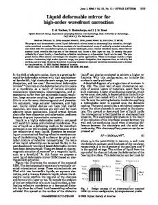
Figure 1. Phase A of CANARY showing the camera and DM connectivity. FS represents the figure sensor, TT is the tip-tilt mirror, PC represents a computer, NGS is a natural guide star wavefront sensor, RTCS is the real-time control system and DM represents deformable mirror.
server. The maximum frame rate achievable with these cameras was 300 Hz. Camera control (cooling, frame rate, triggering, etc) was not via sFPDP; instead, the Andor Technologies software developers kit (SDK) and PCI control card were used. 2.1.2
Deformable mirror
The DM and tip-tilt mirror were controlled using a 96 channel PCI digital to analogue converter (DAC) card from United Electronic Industries, with custom electronics for voltage conversion. The DM itself was reused from the ADONIS AO system (Jagourel & Gaffard 1992), with 52 actuators (8 × 8) and recently characterised at LESIA (Kellerer et al. 2012). The tip-tilt mirror was made by Observatoire de Paris. A schematic diagram for phase A operation is given in Fig. 1 2.1.3
Camera and DM control
A camera interface library module for DARC was developed to receive the sFPDP pixel streams. The DARC RTCS pipeline then de-multiplexed the pixel streams, calibrated the images, computed the wavefront slopes and performed wavefront reconstruction and DM fitting (using a single control matrix). Comprehensive lists of computational algorithms used in CANARY (and DRAGON) are given by Basden et al. (2010); Basden & Myers (2012); Basden et al. (2014). The DM command vector was then output by sFPDP to a deformable mirror controller (DMC) server. 2.1.4
A figure sensor for open-loop DM control
The DM was operated in open loop, i.e. changes to the DM surface shape were not seen by the WFSs. The DMC included a figure sensor (a Shack-Hartmann WFS) was used to monitor the shape of the DM, and then apply offsets to the DM command vectors so that the actual shape matched c 0000 RAS, MNRAS 000, 000–000
Interface of the infrared science camera
A Xenics Xeva-1.7-320 camera was selected as a science point spread function (PSF) measurement camera, with a maximum frame rate of 60 Hz. An interface module for this universal serial bus (USB) camera was created to allow operation with the RTCS, and it was operated with a separate instance of the RTCS on a dedicated science computer. Integrating this camera with the RTCS gave us several key abilities: the tools for operation of the camera and display and capture of information (locally and remotely) were identical to the rest of the system. Users therefore did not need to learn additional interfaces. This camera was also used to provide tip-tilt closed loop AO control during system calibration of the non-common path aberrations (NCPA).
2.1.6
On-sky operation
For phase A of CANARY, we had two on-sky observing runs of 4 nights each. We were able to successfully demonstrate first MOAO operation, the capability of the Learn and Apply algorithm (Vidal et al. 2010), and first on-sky demonstration of GPUs for wavefront reconstruction.
2.2
Phase B0: LGS commissioning
Two pulsed 532 nm 20 Watt lasers were installed behind the WHT secondary mirror, to provide a single Rayleigh LGS using a polarisation beam combiner. Further details are given by Morris et al. (2011). During operation, these lasers are pulsed at about 10 kHz, requiring a camera with a fast shutter to open and close once each pulse has propagated to and returned from the desired LGS height. Typically, this shutter will be open for 1 µs per pulse with 100 µs between pulses, ruling out any practical mechanical shutter. Therefore, a novel CCD architecture with an electronic (on-silicon) shutter (Lincoln Labs CCID18) was used with a Scimeasure controller and a custom sFPDP pixel stream interface. Unfortunately, this detector suffered electronic damage shortly before the on-sky commissioning, and so a temporary solution using Pockels cells and an Andor Technologies iXon camera was implemented whilst a replacement detector was sourced. During LGS commissioning a PCO.Edge scientific CMOS (sCMOS) camera was used to provide a wide field image of the laser (unshuttered), and was interfaced with the DARC RTCS so that common software tools could be used, including pixel displays and camera controls, reducing duplication of effort. Pixel stream acquisition was not enabled for this camera: since it was not used in an AO loop, this was not required.
4
A. G. Basden et al.
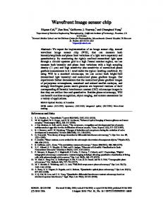
Figure 3. Phase B2 of CANARY showing the camera and DM connectivity. Figure 2. Phase B1 of CANARY showing the camera and DM connectivity. Here, LGS represents the laser guide star wavefront sensor.
The two lasers were polarisation combined to provide a single beam with increased power. A beam combining camera was installed to ensure that alignment of the lasers was maintained. This camera was an IDS Imaging UI-2210SE VGA camera, which was also integrated with the DARC RTCS. A separate instance of DARC was used for this camera, i.e. it was not associated with the main AO loop. The ability to automatically control the laser beam alignment was available because of the RTCS component. A closedsource SDK was used to create the DARC interface module. 2.2.1
On-sky operation
Phase B0 of CANARY received a total of three on-sky commissioning runs (a total of 9 nights) in 2011–2012. 2.3
Phase B1: Single LGS AO operation
After successful installation and testing of the lasers at the WHT, CANARY proceeded with the operation of a single LGS and 4 NGSs in 2012, as shown in Fig. 2. At this phase of CANARY, first successful on-sky demonstration of full linear-quadratic-gaussian (LQG) SCAO operation was demonstrated (Sivo et al. 2014). A custom infrared science camera using a NICMOS detector was introduced, replacing the previous science camera. This new detector had lower readout noise, and could operate with longer exposure times. An interface module for the DARC RTCS was developed, based on a USB interface. 2.3.1
On-sky operation
Phase B1 of CANARY was operated with three on-sky observing runs (a total of 12 nights) in 2012. 2.4
Phase B2: Operation with 4 LGS
Four LGSs were imaged onto four quadrants of the repaired Scimeasure/CCID18 WFS camera, each with 7 × 7 sub-
apertures. A newer model of NGS WFS meant that maximum frame rate could now reach 450 Hz. A schematic diagram is shown in Fig. 3. At this phase of CANARY, on-sky demonstration of tomographic wavefront reconstruction using artificial neural networks was first demonstrated (Osborn et al. 2014), together with first demonstration of tomographic LQG control (Sivo et al. 2013). 2.4.1
On-sky operation
Two on-sky observing runs of 6 nights each were used for this phase of CANARY (B2) in 2013, following an initial 3 nights for LGS integration. 2.5
Phase C1: LTAO operation
CANARY was reconfigured into an LTAO system, by placing the DM in closed loop with the WFSs. At this stage, the LGS WFS camera had again failed, and a replacement was sought at short notice (1 month before on-sky operation). An Imperx Bobcat B0620 VGA camera was selected, using the interline transfer region as an electronic shutter. This camera had a GigE Vision interface. Readout noise restricted LGS operation to about 12 km altitude (LGS return signal decreases rapidly with altitude). Mid-way through phase C1 (during the second set of on-sky nights), this LGS WFS was replaced by a First Light Imaging OCAM2S camera with developments specifically for CANARY (Gach et al. 2016), and a schematic diagram is shown in Fig. 4. The new camera allowed us to increase LGS altitude to about 20 km, though readout problems meant that the EMCCD gain mechanism was restricted. At this phase, computation of pseudo open-loop slopes became necessary. To aid this, a DM figure sensor was installed, this time using a Bobcat camera, operating as part of the main RTCS loop. 2.5.1
Integration of generic GigE vision cameras
The necessity of pixel stream access meant that rather than using the closed-source Imperx SDK, we instead opted to use an open source GigE vision library (Aravis) with modification to provide low latency pixel stream access, i.e. the c 0000 RAS, MNRAS 000, 000–000
Experience with WFS and DM interfaces for wide-field AO
5
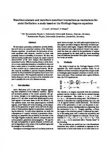
Figure 4. Phase C1 of CANARY showing the camera and DM connectivity.
Figure 5. Phase C2 of CANARY showing the camera and DM connectivity.
ability to access User Datagram Protocol (UDP) packets (and thus begin data processing) as soon as they arrive, rather than waiting for the full frame. The GigE Vision protocol is based on UDP packets, which are inherently unreliable: the Linux Kernel can drop packets if processing load gets too high. Therefore, after investigation, it was determined that to operate these cameras reliably, a hard real-time kernel was necessary, and that the compute thread responsible for reading camera pixels must be restricted to run on CPU cores directly attached to the network card (by setting the thread affinity), with an elevated priority. After these steps are taken, UDP packet loss became negligible, with less than one packet loss per hour. The GigE Vision interface module for the DARC system is suitable for operation with any GigE Vision camera.
additional DM was added to the system (Fig. 5) in openloop, (i.e. the WFSs were insensitive to changes of the DM surface), along with a corresponding figure sensor (a Bobcat). This tweeter DM was an ALPAO DM241, with 17 × 17 actuators. The LGS WFS order was increased from 7 × 7 sub-apertures to 14 × 14, again using the OCAM2S camera, this time with full functionality and sub-electron effective readout noise, allowing LGS height to be increased to about 30 km. It should be noted that this configuration is deliberately similar to that proposed for the MOSAIC instrument (Evans et al. 2013) on the European ELT (E-ELT): A closed loop DM (telescope M4) to provide GLAO correction, and open-loop MOAO DMs. This demonstration was the original goal of CANARY, as proposed in 2007.
2.5.2
2.6.1
Integration of the OCAM2S LGS WFS
Due to the urgent need to replace the Bobcat camera because of high readout noise, and to the very limited time available, a pragmatic approach was taken to integrate the OCAM2S camera. This camera has a Camera Link interface, and was (for the frame grabbers that we had available) restricted to full frame operation, i.e. pixel stream access was not possible. We therefore used a Camera Link to 10GigE Vision converter (an iPort CL-Ten from Pleora), and so could use our existing GigE Vision interface module for DARC. The additional latency introduced by the iPort was negligible, at the micro-second level, and the maximum CANARY frame rate remained restricted by the NGS WFS. 2.5.3
On-sky operation
Two on-sky observing runs (separated by about 3 months) of 6 nights each were used for this phase of CANARY (C1) in 2014. 2.6
Phase C2: Operation at increased WFS order and a woofer-tweeter configuration
In 2015, CANARY was upgraded to provide woofer-tweeter control (Hampton et al. 2006) and a higher order LGS WFSs and SCAO WFS (the Truth sensor). To achieve this, an c 0000 RAS, MNRAS 000, 000–000
Integration of the DM241
The new DM had an Ethernet interface and a closed-source binary SDK. Initial tests showed that there was some latency introduced by this interface, equal to about 800 µs between DM demands being provided to the SDK and the mirror surface settling. For CANARY, the additional latency was not critical due to pseudo-open-loop operation, and we did not have time to develop an alternative solution. To integrate the DM Ethernet interface with CANARY, a new interface module for DARC was developed, to allow operation of the woofer and tweeter together. The commissioning period of the upgraded system prior to on-sky operation was limited to about 1 month. However, due to the flexibility afforded by the DARC interface module system, integration of the new DM was straightforward and no problems arose. 2.6.2
On-sky operation
CANARY phase C2 operated with two on-sky observing runs of 6 nights each in 2015. 2.7
Phase D: Extreme sodium LGS elongation
Phase D of CANARY is planned for the second half of 2016 (Rousset et al. 2014), and will replace the 4 Rayleigh LGS
6
A. G. Basden et al.
with a single sodium LGS, launched about 40 m from the telescope optical axis. During this phase, extreme spot elongation effects will be studied, with techniques developed to mitigate spot truncation and loss of sensitivity along the elongation axis. Designs for the E-ELT include subapertures that are about 40 m from the laser launch axis. Therefore, during CANARY phase D, we are treating the WHT as a sub-pupil of the E-ELT where LGS elongation is greatest. Two observing runs are planned, of 6 nights each. During phase D, we will use the existing CANARY WFS cameras, each with 7 × 7 sub-apertures. The LGS subapertures will have a field of view of 20 arcseconds, to minimise spot truncation. We will also operate a LGS profiling camera on the nearby Isaac Newton Telescope (INT), which will use a high resolution sCMOS camera to image the LGS profile, allowing us to obtain high resolution sodium layer profile images both to derive correlation and matched filter references, and for further study of sodium layer variation. The existing sCMOS interface to the DARC RTCS will be used with modifications to allow dynamic resizing of the detector region of interest. A very simple 3-mode active optics system will be implemented allowing control of tip, tilt and rotation (to keep the LGS elongation axis aligned with the detector pixels).
2.8
CANARY hosted high order upgrade
The installation and test of a high order AO instrument, CHOUGH (Bharmal et al. 2014), is also planned for 2016. This will see CANARY operating in SCAO mode with 31 × 31 sub-apertures at a 1 kHz frame-rate. The camera to be used at this stage is a N¨ uv¨ u HNu 128 × 128 EMCCD camera with a GigE Vision interface. The existing woofer-tweeter DMs will be used, along with a Boston Micromachines Kilo DM, described in §2.9.1.
2.9
The DRAGON wide-field AO bench
DRAGON aims to replicate CANARY concepts, to provide a single channel MOAO system with a woofer-tweeter DM configuration, 4 NGSs and 4 LGSs each with 30 × 30 subapertures. The WFSs are all GigE Vision standard, with the NGS WFSs using the same model of Imperx Bobcat cameras as used by CANARY, and the LGS WFSs using an Emergent Vision Technologies HS2000 10GigE Vision camera. The DARC GigE Vision interface library is used with these cameras, and thus no new developments were required. As a real-time research system, DRAGON enables verification of DARC developments using hardware acceleration including GPUs, and also many-core architectures such as the Xeon Phi (Barr et al. 2015), or POWER8 processors (Basden 2015). Currently, the DARC RTCS has the capability to use GPU acceleration, either just for wavefront reconstruction (first demonstrated on-sky in 2010 during CANARY phase A), or for the whole AO pipeline. Such hardware acceleration capabilities will provide the ability to service increased computational demands from future algorithm development.
2.9.1
DM integration
The woofer DM is a Xinetics 97 actuator DM controlled using a 96 channel PCI DAC card (United Electronic Industries, as used by CANARY) with the central actuator slaved to neighbours (since it is behind the central obscuration). The tweeter DM is a 1020 actuator Boston Micromachines Kilo DM (32 × 32 actuators) controlled using a PCIe fibre optic interface card provided by the DM manufacturer. The tip-tilt mirror is controlled using a 16 channel PCI DAC card (United Electronic Industries). A DARC interface library to control these DMs was required and developed. 2.10
Summary of WFS cameras used in CANARY and DRAGON
Table 1 provides a summary of key information about the WFS cameras that we have interfaced with DARC for operation with the CANARY and DRAGON wide-field AO systems.
3
CHALLENGES FOR WFS AND DM INTEGRATION
The integration of such a diverse set of cameras and DMs using a plethora of different interfaces meant that there were inevitable challenges related to obtaining reliable operation, which we now discuss. 3.1
Missing camera data and dropped frames
For an AO system with multiple camera inputs, it should be assumed that at least occasionally, WFS data will fail to arrive at the RTCS: even in the case of perfect hardware, random events such as cosmic ray events could interfere. During CANARY phase A commissioning, we discovered that the NGS WFSs would regularly deliver partial frames, or insert an extra pixel into a frame. Initially, this occurred about once every 4 minutes. However, in later phases of CANARY, the frequency increased, and became less regular. Our understanding is that this is due to the implementation of the non-standard pFPDP interface, and is beyond our control. Therefore, a software fix, within the RTCS, was required. When using UDP-based cameras (i.e. GigE Vision), packet loss is inevitable at some point, and so must be planned for. 3.1.1
Software handling of incorrect camera data
Correct detection of incorrect camera data is key to AO performance. There are several cases that we have experienced, and thus consider within the DARC WFS interface modules. (i) Dropped pixels: the data frame will be shorter than expected. This condition will be detected when the next startof-frame signal arrives, after pipeline computation from all other WFSs has completed. (ii) Inserted pixels (e.g. a single pixel being duplicated and thus received twice): the end-of-frame signal will be incorrect. This condition will be detected at the end of the frame, probably after pipeline computation has completed, c 0000 RAS, MNRAS 000, 000–000
Experience with WFS and DM interfaces for wide-field AO Model Andor 860
iXon
Pulnix TM6740GE PCO.Edge 5.5 UI-2210SE Xeva-1.7-320 Camicaz Scimeasure/ CCID18 Bobcat B0620GE OCAM2S HS-2000 HNu 128
Type
Phase
Information
Interface
NGS, LGS commissioning
A, B, C, D
figure sensor
A
Control via manufacturer PCI, pixels via sFPDP GigE Vision
LGS commissioning LGS beam combination IR science IR science LGS
B0
EMCCD. PCI compatibility problems for sFPDP daughter board used to send pixel stream SDK unusable with modern Linux systems sCMOS
LGS, figure sensor, NGS LGS LGS High order SCAO
A B, C, D B2 C, D, DRAGON C1, C2 DRAGON CHOUGH
Full source code Yes
No
Camera Link
No
USB-2
No
Custom built Electronic silicon shutter
USB-2 USB-2 AIA to sFPDP
No Yes No
C1 as LGS, NGS for DRAGON
GigE Vision
Yes
Used with iPORT converter
10GigE Vision 10GigE Vision GigE Vision
Yes Yes Yes
B, C
7
Table 1. A table summarising key WFS parameters
i.e. wavefront reconstruction will have been performed based on corrupt data. (iii) Complete frame missing: the DARC interface will not receive any data for this frame. This condition will be detected when AO pipeline computation for all other WFS interfaces has completed and not yet started for the dropped frame. (iv) Dropped Ethernet packets: UDP packets from GigE Vision cameras fail to arrive. This condition is detected using the packet counter embedded within packets, and will be detected as soon as the next packet arrives, while pipeline computation is ongoing. Within our interface, we do not make allowance for packet reordering since we have not discovered this occurring. Therefore, an out-of-order packet is taken to signify a missing packet. These error conditions are detected and handled by DARC. Upon detection, a flag is set to specify that the DM command vector should be frozen for that frame, and that the integrator should not be accumulated. Fig. 6 demonstrates a time-line for three cases. During a good frame, the pixels from different camera types arrive and are processed. Note, different arrival times are due to the differences in camera readout times (different camera models). In the second case the arrival of a camera frame is delayed until after all other cameras have finished readout, this is detected and the pipeline aborted, i.e. DM commands are not sent. In the third case a corrupted frame is detected in one camera, processing is aborted and DM commands are not sent. Internally in DARC, one CPU thread is dedicated to each camera to transfer pixels into a circular buffer for further processing by the CPU threads responsible for RTCS pipeline computation, which we term sub-aperture processing threads. Processing of these pixels proceeds as soon as enough pixels to fill a given sub-aperture have arrived, and a single thread then calibrates the sub-aperture, computes the wavefront slope and performs a partial wavefront reconstruction. We term this a horizontal processing strategy, and further information is given by Basden et al. (2010). The pixel arrival buffers are typically quadruple buffered, i.e. a circuc 0000 RAS, MNRAS 000, 000–000
Figure 6. A figure showing three cases for pixel arrival. The top portion shows a good frame with all pixels arriving as expected. The middle case shows the action taken if one camera is delayed to beyond all others being finished (or fails to arrive). The third case shows arrival of a corrupted frame.
lar buffer with space for four camera frames, though this depends on the DARC camera module being used. Fig. 7 provides a schematic diagram of this approach. Quadruple buffering will ensure that with a real-time kernel no data is overwritten before it has been processed, and that with a non-real-time kernel, this is also very unlikely.
8
A. G. Basden et al. 1.8
7x7, 250Hz 14x14, 250Hz 14x14, 500Hz 30x30, 500Hz 30x30, 1000Hz
H-band rms wavefront error / radians
1.6
1.4
1.2
1.0
0.8
0.6
0.4
0.2
Figure 7. A figure showing how pixel data is handled in DARC. Camera pixels are directed to a small circular buffer which is then read by the sub-aperture processing threads. In the upper half, these threads are processing a completed frame, and in the lower half, the threads have moved on to begin processing the next, currently incomplete, frame.
10
20
30 40 50 60 Probability of corrupt frame / %
70
80
90
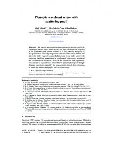
Figure 8. A figure showing AO performance (rms residual wavefront error) as a function of probability of a corrupt WFS frame (for any given frame). For CANARY, this probability is well below 1%.
3.1.2
Due to the use of this horizontal processing strategy, the detection and mitigation of corrupted image frames is nontrivial: by the time an error condition is detected, most of the computation for this and other WFSs will already have been performed, including wavefront reconstruction, update (decay) of the integrator, and update of sub-aperture tracking algorithms (adaptive windowing). It is therefore necessary to reset these parameters to the previous state. It is absolutely essential to ensure that DM command vectors are never sent to the DM based on a corrupted camera frame. Temporal forecasting from a previous frame is not a necessary strategy for CANARY-scale systems: simply freezing the DM state for a frame does not significantly degrade performance (§3.1.2). Maintaining synchronisation between the different WFSs (i.e. so that one camera does not lag others by an integer number of frames) is achieved by only using the most recent whole or partial frame after a previous frame has finished. As previously mentioned, one CPU thread per camera is used to transfer pixels into a circular buffer. When starting a new frame, the sub-aperture processing threads first check whether there is currently an active frame being read from the camera (i.e. whether the first pixels have already arrived). In this case, this frame then proceeds to be processed. If this is not the case (i.e. there is not currently a frame arriving) then the most recently acquired frame will be processed if it has not already been processed. In this way, if a WFS does begin to lag (if, for example, another WFS has missed a frame), a frame will be dropped, and differential latency removed. Although this approach might seem obvious, it is worth a mention here as an issue that requires thought, i.e. is non-trivial. We note that this approach enables reliable operation on non-real-time operating systems, i.e. scheduling delays do not allow frames to stack up for processing.
0
Impact of corrupt image frames
The effect of missing or corrupt image frames on AO performance for CANARY is relatively low. Being a moderate order (pseudo) open-loop AO system, AO bandwidth error forms a relatively small part of the overall error budget, and so the occasional additional single frame of latency has little impact. Fig. 8 shows Monte-Carlo simulation results (H-band rms wavefront error) for a CANARY-like system (using only the on-axis Truth sensor) as a function of probability of missing WFS frames. These results are for a SCAO system on a 4.2 m telescope and consider a 7 × 7, 14 × 14 and 30 × 30 order AO system (Fried geometry), relevant for the different phases of CANARY, and for CHOUGH and DRAGON, at different frame rates. It can be seen that when the probability of a missing frame is low (1%), the impact on performance is negligible. For the CANARY WFSs, the probability of a corrupt frame was found to be below the 0.1% level, and therefore we are confident that our occasional corrupt frame has not reduced AO performance with any significance: other errors dominate. Nevertheless, we recommend that WFS cameras should be well tested for these transient errors before acceptance. These Monte-Carlo simulations use parameters that are used during CANARY design studies, including a 3-layer atmosphere with a Fried’s parameter of 12 cm and an outer scale of 30 m. Within the simulation, a corrupt image frame would be simulated with a specified probability (Poisson distributed), which would then result in the DM being frozen for that frame. Our technique for freezing system state within DARC (e.g. resetting integrators to their previous values) upon detection of a corrupt frame also applies to pseudo-open-loop slope calculation. 3.2
Camera trigger synchronisation
Cameras in both CANARY and DRAGON are externally triggered using a common frequency trigger signal, though with a selectable delay for each camera. For most phases of c 0000 RAS, MNRAS 000, 000–000
Experience with WFS and DM interfaces for wide-field AO
Figure 9. A figure showing hardware used to access the pixel stream from Andor iXon cameras.
CANARY, this delay was set so that the last pixel of each frame from each camera would arrive at the RTCS at the same time. This approach minimised latency, allowing the DM shape to be set as soon as possible relative to the camera exposures. However, this approach means that different cameras are exposed for different periods of time, leading to complications for pseudo-open-loop control (POLC) operation during phase C. At this point, we therefore triggered cameras to have the same mid-point exposure time (i.e. the middle of the exposure coincided for all cameras). Camera synchronisation can also be complicated by the inlcusion of integrated electronic shutters that are used with the Rayleigh LGS WFS detectors. Whilst this is by no means a standard technology used within astronomy, the development of pulsed sodium lasers may mean that it becomes a standard requirement. Dependent on the implementation of the shuttering within the camera, the laser pulses must also be synchronised to the camera readouts, requiring a centralised timing system capable of nanosecond jitter feeding signals to several distributed locations across the telescope.
The Pulnix camera used a binary SDK last updated in 2009, to which source code access was not available. Fortunately, this camera was only required for phase A, and so future compatibility has not been an issue. Should we require use of this camera in the future, the newer generic GigE Vision DARC interface (for which full source code is available) would be used, also having the advantage of pixel stream access. The sCMOS camera has a Camera Link interface, and requires closed source drivers for the frame grabber, as well as for the camera SDK (from different manufacturers). As of 2015, these drivers have remained in active development, and it has been possible to continue to operate the camera with up to date Linux kernels. However, obtaining these drivers can be difficult. The Scimeasure controller for the CCID18 detector uses an AIA frame grabber card (necessary for camera control, even though we use sFPDP for receiving the pixel stream), requiring a PCI interface (which are becoming less common). Drivers are still available, though in binary format from the frame grabber manufacturer. A waveform compiler is also necessary, and exists as a Windows executable (which we use on Linux under Wine). As mentioned previously, our discovery of the opensource Aravis library for GigE Vision cameras, and our modification of it meant that any GigE Vision camera now has an interface to DARC which relies only on the presence of a network interface, rather than a commercial frame grabber. In the case of the OCAM2S camera, a close collaboration with the camera manufacturer, and an investigation of UDP packets was necessary to develop a functional solution including full camera control.
3.4 3.3
Camera driver issues
Over the operational period of CANARY, we have had a large number of different cameras interfaced to the CANARY RTCS system. Most of these cameras have relied on closed-source software drivers, and as a result we have experienced incompatibilities between required Linux kernel specifications and software stacks, particularly for older cameras which often do not see the related software updated for newer Linux kernels. For operation at phase A, we obtained (under a nondisclosure agreement) source code for the sFPDP receiver card used for capture of NGS pixels. This was then essential at phase C when we upgraded the RTCS server, to allow the sFPDP interface to continue to work with a newer Linux kernel. EMCCD camera control was performed using the standard camera interface card from Andor Technologies, which has good driver support. Unfortunately, our extension to enable a sFPDP pixel stream relies on a PCI card that we have only managed to operate with one specific motherboard type, and of which our spare supplies are running low. We have therefore developed a new method for producing the sFPDP stream, using a FPGA based board which attaches to the standard Andor Technologies camera output, acting as a pass-through device for the standard image data, and also providing a sFPDP (or Ethernet) pixel stream, as shown in Fig. 9. This system is likely to be used from 2016 onward. c 0000 RAS, MNRAS 000, 000–000
9
Cabling of cameras
The stability of an AO bench is paramount and it is necessary to keep electronic and computer racks some distance from the optics to avoid heating, air-flow and vibration effects. For CANARY, where possible, computers and electronics are located in an electronics room, adjacent to the optical bench area. The available cable length for our Andor Technologies cameras was limited such that we had the controller PCs mounted on an above-bench frame, with the sFPDP link extending from these PCs to the RTCS (with fibre length being essentially unlimited for our purposes). For Ethernet based cameras, cable length is not an issue, as Ethernet cable lengths are ample for our requirements. Camera Link cables of up to 10 m lengths are also available, again allowing a direct connection between camera and the RTCS in a separate electronics room. We have found that some Ethernet cameras get hot during operation, which means thermal control should also be considered.
3.5
DM driver issues
The low order CANARY and DRAGON DM and tip-tilt mirrors are controlled using custom electronics driven from a commercial PCI DAC card. We have access to the source code for the drivers of this card, which has allowed us to make modifications for newer Linux kernels.
10
A. G. Basden et al.
The high order CANARY DM is operated using Ethernet, though this solution still required use of a closed source binary (at the user level, i.e. without any kernel drivers necessary). The Boston Kilo DM uses a PCIe fibre card, for which closed-source drivers are available for Linux. Fortunately, the Kilo DM drive electronics are modular, allowing a different DM interface to be used in the future, should the need arise.
3.6
Lessons learnt and key points for consideration
Our extensive experience with WFSs and DMs for wide-field AO systems has provided us with several key considerations to be taken into account during the design of future AO systems. Many of the problems that we encountered were specific to CANARY, however the lessons that we learned are highly relevant for future AO systems. Closed source drivers and binary SDKs are problematic because of potential future incompatibilities with newer Linux kernels due to changes in the application binary interface specification, and should be avoided where possible. Systems using commonly available hardware interfaces such as Ethernet should be favoured, and pixel stream access will significantly reduce AO latency. Maximum cable lengths should also be given consideration. As astronomical AO technology becomes more mainstream, emphasis on commodity hardware and open source software becomes increasingly important. Synchronisation of WFSs and correct handling of corrupted image frames is non-trivial due to the pipeline nature of AO processing, and should be considered at the design phase of AO system development. The impact of corrupted frames on all aspects of the system (telescope offloads, telemetry data storage, etc) should be considered. A single RTCS system with which to operate all cameras has also been beneficial (including cameras that are not WFSs), allowing a single interface to be used, significantly reducing the learning curve for system developers. This also reduces the effort required to develop camera control tools, graphical interfaces, etc, and simplifies project development.
4
CONCLUSIONS
The CANARY AO demonstrator instrument has been operated on-sky over a six year period, with many different instrument development phases, aimed at testing and demonstrating new AO concepts and technologies. During this period we have acquired significant expertise related to integration of WFS cameras and DMs with the AO RTCS, DARC. Here, we have described the different phases of CANARY operation, providing details of the WFS and DM interfaces required at each phase, and how these have been integrated with the system. An overview of the DRAGON AO bench has also been given, along with the approach taken for integration of WFSs and DMs with the RTCS. We have discussed the problems that were met and overcome, and have provided recommendations for future AO systems. In summary, for long-life expectancy AO systems, we recommend the use of Ethernet based cameras and DMs where possible
to extend operational instrument lifetime, to enable continued compatibility during future system updates, and to remove the requirement for product specific frame grabbers or other hardware. Open-source software, or as a minimum, access to source code for all kernel module driver interfaces greatly increases the future maintainability of these systems, allowing continued developments, updates and repairs to be made.
ACKNOWLEDGEMENTS This work is funded by the UK Science and Technology Facilities Council, grant ST/K003569/1, and a consolidated grant ST/L00075X/1. D. Guzman appreciates support from FONDECYT grant 1150369. Supported in France by Agence Nationale de la Recherche (ANR) program 06-BLAN-0191, CNRS/INSU, Obs. de Paris and Univ. Paris Diderot ; supported by European Commission FP7: E-ELT Prep. Infrastruct. 2007-1 Grant 211257, OPTICON program Infrastructures 2008-1 Grant 226604 (JRA1) and 2012-1 Grant 312430 (WP1)
REFERENCES Babcock H. W., 1953, Pub. Astron. Soc. Pacific, 65, 229 Barr D., Basden A. G., Dipper N., Schwartz N., 2015, MNRAS, 453, 3222 Basden A. G., 2015, MNRAS, 432, 1694 Basden A. G., Bharmal N. A., Bitenc U., Dipper N., Morris T., Myers R., Reeves A., Younger E., 2014, in Society of Photo-Optical Instrumentation Engineers (SPIE) Conference Series Vol. 9148 of Society of Photo-Optical Instrumentation Engineers (SPIE) Conference Series, Real-time control for the high order, wide field DRAGON AO test bench. p. 4 Basden A. G., Geng D., Myers R., Younger E., 2010, Appl. Optics, 49, 6354 Basden A. G., Myers R. M., 2012, MNRAS, 424, 1483 Bharmal N. A., Myers R. M., Basden A. G., H¨ olck D., Morris T. J., 2014, in Society of Photo-Optical Instrumentation Engineers (SPIE) Conference Series Vol. 9148 of Society of Photo-Optical Instrumentation Engineers (SPIE) Conference Series, CHOUGH, the Canary HostedUpgrade for High-Order Adaptive Optics. p. 5 Evans C., Puech M., Barbuy B., Bastian N., Bonifacio P., Caffau E., Cuby J.-G., Dalton G., Davies B., Dunlop J., Flores H., Hammer F., Kaper L., Lemasle B., Morris S., 2013, ArXiv e-prints Fedrigo E., Donaldson R., Soenke C., Myers R., Goodsell S., Geng D., Saunter C., Dipper N., 2006, in Advances in Adaptive Optics II. Edited by Ellerbroek, Brent L.; Bonaccini Calia, Domenico. Proceedings of the SPIE, Volume 6272, pp. 627210 (2006). Vol. 6272 of Presented at the Society of Photo-Optical Instrumentation Engineers (SPIE) Conference, SPARTA: the ESO standard platform for adaptive optics real time applications Gach J.-L., Feautrier P., Buey T., Rousset G., Gendron E., Morris T. J., Basden A., Stadler E., Myers E., Vidal F., Chemla F., 2016, in Gavel D., Trancho G., eds, Proceedings of the Fourth AO4ELT Conference OCAM2S: an c 0000 RAS, MNRAS 000, 000–000
Experience with WFS and DM interfaces for wide-field AO integral shutter ultrafast and low noise wavefront sensor camera for laser guide stars adaptive optics systems. p. 58 Gendron E., Vidal F., Brangier M., Morris T., Hubert Z., Basden A. G., Rousset G., Myers R., 2011, A&A, 529, L2 Hampton P., Bradley C., Agathoklis P., Conan R., 2006, in The Advanced Maui Optical and Space Surveillance Technologies Conference Control System Performance of a Woofer-Tweeter Adaptive Optics System. p. 59 Jagourel P., Gaffard J.-P., 1992, in Ealey M. A., ed., Active and Adaptive Optical Components Vol. 1543 of Society of Photo-Optical Instrumentation Engineers (SPIE) Conference Series, Adaptive optics components in Laserdot. pp 76–87 Johns M., 2008, in Extremely Large Telescopes: Which Wavelengths? Retirement Symposium for Arne Ardeberg Vol. 6986, The Giant Magellan Telescope (GMT). pp 698603–698603–12 Kellerer A., Vidal F., Gendron E., Hubert Z., Perret D., Rousset G., 2012, in Adaptive Optics Systems III Vol. 8447 of Society of Photo-Optical Instrumentation Engineers (SPIE) Conference Series, Deformable mirrors for open-loop adaptive optics. p. 844765 Morris T., Hubert Z., Chemla F., Todd S., Gendron E., Huet J.-M., Younger E., Basden A. G., 2011, in Second International Conference on Adaptive Optics for Extremely Large Telescopes. Online at http://ao4elt2.lesia.obspm.fr, id.P3 CANARY Phase B: the LGS upgrade to the CANARY tomographic MOAO pathfinder. p. 3P Myers R. M., Hubert Z., Morris T. J., Gendron E., Dipper N. A., Kellerer A., Goodsell S. J., Rousset G., Younger E., Marteaud M., Basden A. G., 2008, in Society of Photo-Optical Instrumentation Engineers (SPIE) Conference Series Vol. 7015 of Presented at the Society of Photo-Optical Instrumentation Engineers (SPIE) Conference, CANARY: the on-sky NGS/LGS MOAO demonstrator for EAGLE Nelson J., Sanders G. H., 2008, in Society of PhotoOptical Instrumentation Engineers (SPIE) Conference Series Vol. 7012 of Society of Photo-Optical Instrumentation Engineers (SPIE) Conference Series, The status of the Thirty Meter Telescope project. pp 70121A–70121A– 18 Osborn J., Guzman D., de Cos Juez F. J., Basden A. G., Morris T. J., Gendron E., Butterley T., Myers R. M., Guesalaga A., Sanchez Lasheras F., Gomez Victoria M., Snchez Rodrguez M. L., Gratadour D., Rousset G., 2014, Monthly Notices of the Royal Astronomical Society, 441, 2508 Reeves A. P., Myers R. M., Morris T. J., Basden A. G., Bharmal N. A., Rolt S., Bramall D. G., Dipper N. A., Younger E. J., 2012, in Society of Photo-Optical Instrumentation Engineers (SPIE) Conference Series Vol. 8447 of Society of Photo-Optical Instrumentation Engineers (SPIE) Conference Series, DRAGON: a wide-field multipurpose real time adaptive optics test bench Rigaut F., Neichel B., Boccas M., d’Orgeville C., Arriagada G., Fesquet V., Diggs S. J., Marchant C., Gausach G., Rambold W. N., Luhrs J., Walker S., Carrasco-Damele E. R., Edwards M. L., Pessev P., Galvez R. L., 2012, in Society of Photo-Optical Instrumentation Engineers (SPIE) Conference Series Vol. 8447 of Society of PhotoOptical Instrumentation Engineers (SPIE) Conference Sec 0000 RAS, MNRAS 000, 000–000
11
ries, GeMS: first on-sky results Rousset G., Gratadour D., Gendron E., Buey T., Myers R., Morris T., Basden A. G., Talbot G., Bonaccini Calia D., Marchetti E., Pfrommer T., 2014, in Society of PhotoOptical Instrumentation Engineers (SPIE) Conference Series Vol. 9148 of Society of Photo-Optical Instrumentation Engineers (SPIE) Conference Series, Proposal for a field experiment of elongated Na LGS wave-front sensing in the perspective of the E-ELT. p. 3 Sivo G., Kulcsar C., Conan J., Raynaud H., Gendron E., Basden A. G., Vidal F., Morris T., 2014, Opt. Express, 22, 23565 Sivo G., Kulcsar C., Conan J.-M., Raynaud H.-F., Gendron E., Basden A. G., Vidal F., Morris T., Meimon S., Petit C., Gratadour D., Martin O., Hubert Z., Rousset G., Dipper N., Talbot G., Younger E., Myers R., 2013, in Esposito S., Fini L., eds, Proceedings of the Third AO4ELT Conference First on-sky validation of full LQG control with vibration mitigation on the CANARY MOAO pathfinder. p. 127 Spyromilio J., Comer´ on F., D’Odorico S., Kissler-Patig M., Gilmozzi R., 2008, The Messenger, 133, 2 Su´ arez Valles M., Fedrigo E., Donaldson R. H., Soenke C., Zampieri S., Bourtembourg R., Tischer H., 2012, in Society of Photo-Optical Instrumentation Engineers (SPIE) Conference Series Vol. 8447 of Society of PhotoOptical Instrumentation Engineers (SPIE) Conference Series, SPARTA for the VLT: status and plans. p. 2 Vidal F., Gendron E., Brangier M., Sevin A., Rousset G., Hubert Z., 2010, in Adaptative Optics for Extremely Large Telescopes Tomography reconstruction using the Learn and Apply algorithm This paper has been typeset from a TEX/ LATEX file prepared by the author.