Keywords: Model-Based Testing Automation, Workflow-Driven ... and tools used to automate the development of tests at reduced costs and improved ...... load time, they are instantiated, initialized and registered with the ServiceRegistry.
Experiences using Tedeso: an Extensible and Interoperable Model-based Testing Platform Roberto Silveira Silva Filho, William M. Hasling, Christof J. Budnik, Monica McKenna Siemens Corporation, Corporate Technology Software Architecture Design 755 College Road East Princeton, NJ, USA 08540 Phone: +1 609-734-3614 Fax: +1 609-734-6565 {Roberto.Silva-Filho, Bill.Hasling, Christof.Budnik, Monica.McKenna}@siemens.com Abstract. The integration of novel software quality assurance tools into existing development environments must be performed in ways that leverage the benefits of the tools while minimizing their impact on existing software processes. This supports the adoption of new methodologies with minimal interference into core business practices. This paper discusses the design of Tedeso, an extensible and interoperable model-based testing platform developed to facilitate the automatic generation of tests, while supporting the needs of different stakeholders in a diverse and broad organization. We discuss Tedeso key design characteristics, in particular its extensibility and interoperability, provided through the use of a workflow-driven service-oriented architecture, and show how it has enabled and facilitated the adoption of model-based testing techniques in different business units in different sectors within SIEMENS. We also discuss some issues that come from the adoption of service-oriented architectures, showing how they have been managed in our platform. Keywords: Model-Based Testing Automation, Workflow-Driven Service-Oriented Architectures, Design for Extensibility & Interoperability, Tedeso
1
Introduction
The engineering of software and systems rely on different tools used in support of the many stages involved in their development. Examples include requirements management, design, implementation, testing, and configuration management tools. These tools are typically organized into closely integrated chains combining open and proprietary standards. In fact, the need for close integration between software development tools has originated different open source and proprietary solutions, promoted by vendors such as IBM Rational, Microsoft, and Hewlett-Packard. While this tight integration becomes central to the business at hand, it can become a hindrance for the adoption of novel software engineering approaches. For example, in large organizations as SIEMENS, with many and heterogeneous business units in different sectors such as Healthcare, Industry, Energy, and Infrastructures & Cities, it is not uncommon for different business units to utilize their own combination of software development tools and standards driven by the different needs. In order to be adopted in these environments, novel software engineering methodologies and tools must be able to interoperate with this diverse set of software processes and tool chains. Moreover, they must be able to convey the benefits of the approach they implement in a minimally intrusive way, with as little impact as possible on core business practices, and at acceptable customization and adaptation costs. At SIEMENS Corporate Technology, we have been developing novel software engineering techniques that are utilized in different business units with distinct software practices and tool chains. In particular, we have been researching and deploying novel model-based testing methodologies and tools used to automate the development of tests at reduced costs and improved accuracy. The success of approaches like these are not only dependent on the algorithmic benefits of its approach, but also on how interoperable they are with existing tool chains within the organization. As a response to these requirements, we have been developing extensible and configurable software platforms as Tedeso: test design studio (formerly TDE/UML) (Hasling et al., 2008). Tedeso is a model-driven software testing platform. Model-based testing (or MBT) seeks to utilize abstract models for the generation of software quality artifacts (Dalal et al., 1999). Likewise, Tedeso supports the automatic generation of tests based on system behavior specifications defined in UML. In particular, it utilizes the category partition method (Ostrand and Balcer, 1988) to generate test cases covering different data inputs and paths described in the system behavior specification. Hence, it achieves unprecedented levels of test automation with improved test coverage (Vieira et al., 2008). In addition to the MBT algorithms and features provided by the platform, one of the main challenges in the development of Tedeso was to design a platform that can be flexible, to accommodate both research and custom-driven features, and be interoperable, supporting the use of the tool with existing tool chains throughout SIEMENS business units. In particular, we addressed these challenges through a service-oriented architecture where different services are provided around an extensible model-based testing workflow. In this work we discuss how workflow-driven service-oriented architectures can be applied in the construction of MBT tools that can be extended with new features, and that can interoperate with existing tool chains in large organizations as SIEMENS. As any other extensibility approach, these benefits come at some costs. Hence, we discuss the challenges faced in the design and development of Tedeso, discussing how we mitigate these issues. Finally, we validate our approach by presenting qualitative and quantitative data on the automation benefits of MBT, and on the effort necessary to extend, configure, and integrate Tedeso with existing tool chains. This paper is organized as follows. In section 2, we discuss the challenges and requirements involved in the adoption of novel automated software engineering tools in large organizations, deriving a set of requirements. Section 3 presents our workflow-driven service oriented approach developed to address these requirements. In section 4 we discuss the application of that approach in the design of Tedeso model-based testing tools. Section 5 discusses Tedeso implementation details. Section 6 discusses some pitfalls of the use of service-oriented architectures, showing the approaches adopted to mitigate these issues. In section 7 we validate our approach by presenting case studies where Tedeso was been used to automate test generation, as well as cases where it was extended and integrated to existing quality assurance processes and tool chains. We discuss related work in section 8, and present our conclusions in section 9.
2
Background
Different approaches have been proposed in the industry and academia in the development of interoperable and extensible software engineering tools. These include the use of middleware layers,
the build of proprietary integrated tool chains and the design of tools for flexibility & interoperability. According to Thomas and Nejmeh (Thomas and Nejmeh, 1992), “Tool integration is about the extent to which tools agree. The subject of these agreements may include data formats, userinterface conventions, use of common functions or other aspects in tool construction.” Using this definition, Thomas and Nejmeh characterized the tool integration problem in Software Engineering Environments (SEE) into five aspects: platform, presentation, data, control, and process. Using this framework, existing approaches to tool integration and interoperability have been developed focusing on one or many of these levels. Use of common data representations. Perhaps, the most common ways to support tool integration is the adoption of common data representations. Standardized languages such as UML, and standard UML formats such as XMI (XML Metadata Interchange) from OMG provide a common ground for exchanging data between software tools, in particular, model-based tools. Commercial off-the-shelf tools are usually provided supporting the reading and writing of data in these formats, allowing models and data developed in one tool to be opened by other tools. This approach, however, lacks the support for control and presentation integration proposed by Thomas and Nejmeh. As a consequence, tools exchanging data in these formats may not agree on the semantics and representation of the data. Moreover, standards are usually adopted in relatively mature application domains, for example CAD systems and software modeling, leaving novel domains and applications unsupported. Use of common middleware. On the data and control integration levels from Thomas and Nejmeh’s model, different standards have been proposed in the definition of tool integration protocols. The idea is not only to provide common data representations but mechanisms for data exchange and control. For example, the Open Services for Lifecycle Collaboration (or OSLC) (http://open-services.net) provide a common data and control representation for the integration of different tools. It relies on a common RESTful protocol, and a set of customizable user-defined adapters deployed to web services. These services, allied with existing tool extensibility, can better support the interaction between tools with respect to data, control and presentation (via web interface). Another example is the ModelBus (Hein et al., 2006), that provides tool integration by means of SOA interfaces and custom adapters built around a versioned shared repository. The ModelBus approach moves the extensibility burden from tool developers to a shared data repository. Distributed development is achieved by the use of check-in/check-out protocols and data integration is achieved by adapters attached to the ModelBus. These adapters translate the data from/to existing UML model formats. In spite of these benefits, middleware approaches are generally application-domain agnostic, i.e., they must be applied in the development of solutions across different domains, and opt for a more general support for data and control exchange. Therefore, they require developers to utilize these mechanisms to communicate based on previously agreed standard data and protocols. Design for extensibility. The design for extensibility principle has been applied in different software tools such the InterLisp environment (Teitelman and Masinter, 1981), and modern software development tools such as the Eclipse platform (http://www.eclipse.org) and existing tool chains previously described. These systems leverage on a common data representation, event model, and presentation, providing a platform that can be extended for different needs. Extensibility mechanisms allow tools to be customized to different application domain’s needs. This approach has been popularized by open source tools as Eclipse, and commercial tools as Microsoft Visual Studio, that adopt plug-in oriented architectures (Birsan, 2005) supporting the customization of data, control and presentation. Their extensibility, however, is usually limited to the software environment set of functions, for example, users can tailor the tool to visualize new programming languages, to call different compilers or interact with third party configuration management repositories. There is, however, a lack of orchestration mechanism that allows these functions to be combined in support of the user workflow, i.e., an automated way to guide users in the process of utilizing these features. Verticalized tool chains. Finally, an increasing approach for tool integration has been the development of verticalized products that share common data, control and presentation layers. That’s the predominant approach adopted by tool vendors such as Microsoft, IBM and HP. Examples of tools employing these approaches include: IBM Rational, IBM Jazz, Microsoft Visual Studio, and others. Besides the use of proprietary formats, these tools usually provide public APIs that support the development of add-ons. Examples of public APIs include HP Open Test Architecture (or OTA), and IBM Collaborative Lifecycle Management.
While these approaches provide a common presentation, control and data representation, and facilitate the development of extensions through public APIs, plug-ins and add-ons, their extensibility is limited to the extent these tools provide access to key elements of the platform. This prevents the adoption of the approach in business units without access to core parts of those vertical tools. In a practical sense, these many approaches end up coexisting with one another. For example, it is common to see business units that combine open source products with verticalized tool chains and standard data representations. Moreover, tool integration is not only about data, protocols and presentation, but also process integration, i.e., they must be able to coexist with agile, structured and incremental approaches.
3
Workflow-driven Service-oriented Approach
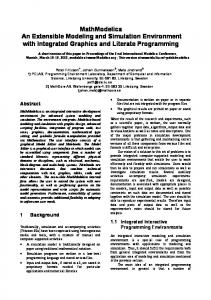
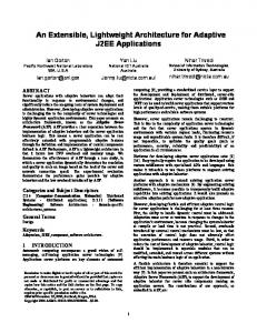
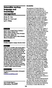
Our challenge in the design of Tedeso is then to implement and ship a novel model-based testing methodology in a way that maximizes its interoperation with existing tool chains, and allows customizing the tool to different customer needs. Our answer is the adoption of the following set of principles in the design of successful platforms in heterogeneous organizations. Design for extensibility. The design of the tool must support its adaptation to the needs of different stakeholders. Mechanisms such as extension points and public APIs must be supported. In other words, the tool must be designed as a platform for both innovation and adaptation to individual organization needs. In our approach, we utilize services as the extensibility mechanism. Design for interoperability. Interoperability requires special attention to the reuse of existing standards, and to the definition of strategic extension points in the platform for interacting with other tools, in particular along its data representation; thus our platform supports the use of adapter and importer services. Adoption of existing standards. The reuse of existing standards and languages contribute to the reduction of the semantic gap between the novel approach and existing tools. It is usually tempting to define one’s own approach, model and languages when implementing novel tools. Too much innovation, however, may backfire and result in incompatible and overly complex approaches that may not be well received in existing organizations. Instead, we propose a more backward compatible approach, one that strives to reuse existing models and standards as much as possible, while introducing innovation in strategic points. In Tedeso, we utilize UML 2.0 language as the common model representation, representing model extensions in a backward-compatible way with this standard, for instance, utilizing profiles, stereotypes and notes. Workflow-driven service-oriented approach. Finally, integrate the extensibility, interoperability and standard data representations in the form of a service-oriented architecture (Haines and Rothenberger, 2010), with the orchestration capability of domain-specific workflows. The workflow captures the domain expertise in the form of abstract decision points and steps, providing optional points where extensibility can be supported, and assuring that the approach steps are followed in the correct order. These points are then extended by customized services, designed to meet the needs of different stakeholders. While existing approaches combining services and workflow have been proposed for web services composition (Piccinelli et al., 2003), business process automation (Yongyi et al., 2009), compiler construction (Ekman and Hedin, 2007) and notification servers (Silva Filho et al., 2003), few have studied the application of such an approach for model-based testing tools, with an emphasis on interoperability and flexibility. Figure 1 illustrates our approach. Workflow steps are depicted as grey boxes. They represent abstract activities that the user can execute within an application domain, for example, a model-based testing approach. Arrows represent dependencies between these steps, generally caused by data and control dependencies. Data elements are represented as black boxes. Data flows from one step to another, being potentially refined and modified within each step. Along this workflow, services represented as white boxes, implement the functionality of each step. Services can be further customized by composing sub-services. For instance, in complex activities such as model-based test generation, the UML activity diagram generator can be implemented by different sub-services, one for each compilation stage as, e.g., path expansion and data binding. Hence, services can explicitly depend on other services, or may have implicit dependencies to other services, for example, the data consumed by service C may be derived from the data produced by service A, requiring both services to be installed in the system at the same time, and be executed in the predetermined order.
Sub-service A1
Sub-service A2
Service B
Output Data Service A
Workflow Step 2.1 Workflow Step 1
External / Input Data
Data’’ Workflow Step 3
Data
Workflow Step 2.2
Data’ Service C
Output Data
Figure 1. General workflow-driven service-oriented approach By expression a domain expertise as a workflow-driven service-oriented architecture, a set of features provided by a complex approach such as model-based testing, can be combined in a more systemic way, allowing users to select among steps, pick individual functions, and ultimately customize the tool to their need. From a usability perspective, this architectural style allows the knowledge of the approach to be embedded in the tool as a workflow, i.e., a set of steps and options to be followed. This eases the UI to provide guidance to end-users, detecting when required steps were not followed, and prompting the user for the right information, at the right time. For example, in model-based testing, the generation of tests must necessarily precede the generation of executable code, while the checking of the model for errors can be optional. By utilizing the information about step dependencies, these rules can be enforced. Optional steps can also be defined, allowing users to freely select services and the order they are applied, as long as the core process dependencies are obeyed. From a developer perspective, the use of such architecture supports the development of customized services that can interoperate with external tools, at each point of the workflow. We illustrate those points in the next section where we describe the Tedeso platform.
4
Tedeso Approach
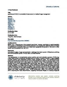
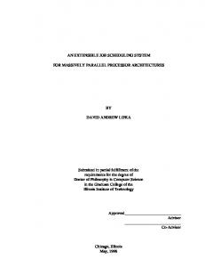
We applied the aforementioned approach in the design of Tedeso, a model-based testing (or MBT) platform that supports the automatic generation of test cases, according to different data and control coverage algorithms. In particular, Tedeso uses the category partition method (Ostrand and Balcer, 1988) to generate abstract and executable tests. The generation process is based on annotated activity and sequence UML diagrams, with control and proprietary data constraints attached to notes and transitions in those diagrams. These diagrams are then parsed to generate abstract test steps that can be converted into all sorts of executable test code or reports. Figure 2 shows an example of an activity diagram for a fictitious digital camera, originating abstract and executable tests for every possible path and data combination in the model. In this example, Tedeso produces different test steps, representing combinations of shooting modes (video or picture) and zoom modes (optical or digital). By automating the process of test generation, Tedeso supports software testers in the process of software quality assurance, and the development of high-assurance systems. Moreover, by relying on automation, it achieves high levels of test coverage with reduced development effort (Vieira et al., 2008).
Modeling
Test Generation
selectVideoMode(); selectZoomMode(optical) shootVideo() verifyVideo(); ... selectVideoMode(); setZoomMode(digital); shootVideo() verifyVideo(); ... selectPicMode(); selectZoomMode(optical); takePicture() verifyPicture();
Code Generation Figure 2. Typical sequence of steps: from modeling, to tests and code Under the hood, Tedeso is designed as a workflow-driven service-oriented architecture as discussed in section 3, where services (also called plug-ins in Tedeso) are installed at different points along a generalized model-based testing workflow. In particular, we support the design principles previously discussed as follows. Design for extensibility and adaptability along a common workflow. Tedeso prescribes a set of high-level MBT steps from data import, data modeling, test generation, code generation, report generation. For each one of these steps, users can select among existing services, or can contribute with their own service implementations. These services are then automatically called, for the currently selected UML model, producing tests, reports and code. Design for interoperability. From the beginning, Tedeso supports the notion of importers and exporters of content. This allows the system to produce reports and executable tests based on specification models allowing the system to import UML models from third party tools. For example, models can be imported from Sparx Systems Enterprise Architect; executable tests can be produced to different existing test execution engines as Junit, NI TestStand, HP Quick Test Pro; or more elaborate test plans can be produced to HP Quality Center. Representation of tool-specific concerns in a non-intrusive, backward compatible way. In the design of the tool, we chose to represent models in a standard way, based on UML, while providing mechanisms that allow tool-specific concerns to be expressed as notes, thus supporting interoperability with other UML tools. This allows, for example, the models to be developed in third party tools as Sparx Enterprise Architect or IBM Rational Rose by using provided Tedeso profiles. Use of a workflow-driven user interface. We utilize the domain-specific workflow of the system to develop a user interface that allows users to better navigate through the different steps and options of the approach. In this approach, the user interface changes according to the installed components, and provide a wizard mechanism that allows users to navigate through the different test generation options and steps of the system according to Figure 1.
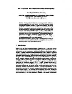
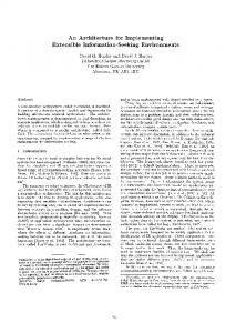
4.1 Tedeso Architecture Tedeso is designed as a workflow-driven service-oriented architecture, where its major concerns in modeling and generation are extensible by means of services. As shown in Figure 3, grey boxes represent the main MBT workflow steps supported by Tedeso. These workflow steps are inherent extension points where specialized services are installed. Services manipulate data represented as
black boxes. In Tedeso, services are integrated in the production of abstract and executable tests and reports based on UML models, according to a high-level workflow. Services may extend other services, as exemplified by data, path and test suite modifiers.
Test and report generation
Model design and checking
Custom model report generators
Custom adapters
Model Import/ Export
Custom model check rules
Model Editor
Model Rule Verification
Custom model editors
Model Parts & Figures
Model Views
Model Report Generation
Custom test report generators
Reports
Test Report Generation
UML Model
Language-specific generators
Test Generation
Test Suite
Test Code
Diagram generator
Editor commands
Data modifiers
Test Code Generation
Path modifiers
Test suite modifiers
Figure 3. Tedeso model-based architecture overview UML Model: Tedeso test models include package, use case, activity, sequence, and class diagrams as defined in UML 2.0. Other diagrams can optionally be provided. Extra information used for test generation and other features are represented in the models by means of custom stereotypes, element properties and OCL-like annotations (Richters and Gogolla, 1998). Note that this extended notation does not break backward compatibility with existing UML tools, as they are all contained in regular UML elements. In particular, we rely on UML support for stereotypes and notes. Model Import/Export: The model import step supports the development of adapter services for different tools. For example, an importer may be developed to read Sparx Systems Enterprise Architect UML models or other standard UML file formats. Once imported, the model is loaded into the system, in our own model tree representation, and becomes available for every step in Tedeso workflow. On the same token, model exporters allow the saving of Tedeso models to different formats, including our own XML representation. Model Editor: Different UML diagrams can be supported. For each diagram, custom model editors can be defined. In particular, the current version of Tedeso utilizes a GEF-based UML editor that supports the creation of different models including: activity, sequence, component, deployment, use case and class diagrams. Model Rule Verification: During model design, it is common for models to have syntactic and semantic mistakes. In order to catch these mistakes, models are frequently checked for errors. In particular, Tedeso supports syntax and semantic checking of its own constraint language defined within notes in the model. Since model checks are services, custom checks can be developed as necessary. Model Report Generation: Provides support for the generation of documents describing different aspects of models. For example, HTML, XML and rich text format reports of existing models. Model reports are important for offline verification and archival. Test Generation: During the test generation, the annotated UML model is parsed and processed, producing an abstract set of test cases and procedures represented as a Test Suite. This process is configurable and extensible through the use of: data, path and test suite modifiers, which imple-
ment coverage algorithms. For example: happy path (user-defined critical path) path modifier, full data coverage modifier, and test suite filtering and prioritization. These modifiers are organized in a pipe-and-filter fashion, with implications further discussed later in this paper. Test Suite: Is a data structure representing a list of test procedures derived from UML models. Test procedures are the basic product of test generation. They describe a list of test steps, operating over specific data bindings. Hence, test suites are used as abstract test descriptions that are input for executable code generators and reports. Test Code Generation: The code generation is based on the abstract test model described in Test Suites. Based on that information which is combined with code-level annotations of the model, generators are used to produce executable test procedures. An important feature of test suites is its use of backward links to model elements, which improves the flexibility of generators, that can utilize model information to improve their output, for example, supporting regression testing as described at (Silva Filho et al., 2010). Test Report Generation: Test Suites can also be used as a basis for generating more detailed test reports, example.g., summarizing test coverage information, or producing a list of manual steps to be followed by User Interface (or UI) testers.
4.2 Example: Using Tedeso to Test a Digital Camera The modeling and generation of tests with Tedeso presumes three major steps. First, the specification of the system in terms of UML diagrams (use cases refined by activity or sequence diagrams); followed by the generation of abstract tests based on this model specification; and finally, the generation of executable tests and reports.
4.2.1
System Modeling
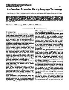
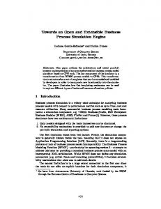
The first step in the use of Tedeso is the definition of a system specification based on use cases as shown in Figure 4.
Figure 4. Example of a digital camera picture shooting use case Each use case is further refined by an activity or sequence diagram as the one shown in Figure 5. These diagrams can include other use cases as repressed by type of activities.
Figure 5. Digital camera activity diagram, illustrating the use of categories In the example of Figure 5, we see the description of single use case called “take a picture”. This use case has different variations, based on camera settings and user decisions. For example, when the camera is first turned on, one can select between taking a picture or a video. These procedures are further defined in other use cases thus the stereotyped activities in Figure 4. After the execution of either activity, the camera saves the data in its own media, which can include the PC, the memory card, or in case of not having any storage the data is kept in the camera RAM. After taking a picture or a video, the media can be manually or automatically visualized. Note that the decision points of this simple use case are based on variables defined in terms of different categories. A category is a class of behavioral equivalent data elements, or choices. Such choices can be either data values, references to other categories or a combination of both. An example of categories is shown in the diagram of Figure 6. Note that in Tedeso, categories are represented as classes, a UML 2.0 compatible way.
Figure 6 Categories diagram, integrating different choices
4.2.2
Test generation
The test generation process consists in traversing the graph defined by the activity diagram according to different path and data coverage algorithms provided by Tedeso services. Currently, we support the following path coverage algorithms: all paths, all activities and happy path. The happy path is formed by a common set of activities in the system, marked by the “happy-path: yes” property, representing a common use case that one can execute in order to quickly validate a system. Likewise, different data coverage options are provided: exhaustive, that uses all choices from all diagram categories; choice-per-path, that randomly picks a single choice per path; and choice-pervariable that picks a single choice per variable, as well as happy-data, that selects the preferential choices defined for each variable through the expression: “[happydata=choice]”. The simple model of Figure 5 can originate different test procedures, defined as combinations of activity sequence paths and data choices. For example, based on different test generator settings Tedeso can produce different sets of test cases, achieving different levels of coverage. Table 1 illustrates the effect of different path and data algorithms in the number of test procedures generated by Tedeso using the digital camera example. It also reports the time it takes to generate the test suite, and activity diagram coverage obtained by each test strategy. All tests were executed in a Windows XP PC running on an Intel M620 i7 processor at 2.66 GHZ, and with 4GB of RAM. In Table 1 we exemplify the results of applying different test coverage options, and the correlation between model coverage thoroughness and the number of tests it takes to achieve these levels. It also shows the effect of different algorithms in optimizing these trade-offs. For example, one can achieve a good balance between the amount of test that needs to be performed, and the data and activity coverage by picking the “choice-per-path” algorithm.
Table 1. Variations in choice and path and their effect on the number of tests produced
4.2.3
Path coverage algorithm
Data coverage algorithm
number of test procedures
Use case activity coverage
Use case data coverage
TestSuite generation time (ms)
all-paths
exhaustive
4320
100%
100%
8248
all-paths
choice-perpath
346
100%
77.8%
2437
all-paths
choice-pervariable
90
100%
44.45%
609
all-activities
choice-perpath
26
100%
77.8%
226
happy-path
happy-data
1
33%
26%
125
User interface: supporting service selection along the MBT workflow
One important challenge induced by Tedeso’s extensible architecture is the need to support endusers in navigating through its model-based testing workflow, supporting the selection of appropriate services to apply at each step of this process. Another important problem that arises in the use of this approach is debugging, i.e., how to support users in understanding the impact of their MBT algorithmic choices in the generated test suite. In order to address those issues, Tedeso test generation UI currently supports two modes, an expert mode where every service option is presented to the user at once, or an interactive wizard mode, where test generation options are presented to the user in an incremental interactive fashion, allowing users to gauge the intermediate test generation results, based on their algorithm choices. In this section, we illustrate the test generation process using the interactive wizard mode. In the interactive wizard mode, the user initiates the test generation process by selecting a use case in a diagram, in our example: the Shooting use case in Figure 4, and by picking the code generation command in its right click context menu.
Figure 7. Use case selector and workflow steps configuration A test generation wizard is then started that guides the user through the different path, data and test suite generation options, implemented by the different services of Tedeso. This wizard is interactive, allowing the user to visualize the intermediate test results (i.e. the current state of the test procedure suite), and to navigate back and forth to change their test generation options.
In the first screen, shown in Figure 7, allows the use to select a saved set of test configuration options. The user can also opt to include the model checks and/or generation of test steps. In the next step, shown in Figure 8, different model checkers are executed in the system. They verify that the model syntax is correct and that the notes are defined according to Tedeso’s test specification language. The result is presented in a tabular way in the form of warnings and errors, allowing users to go back to the model by clicking on the check violation.
Figure 8. Model checker After the model is checked for errors, the user can select among existing path coverage algorithms as shown in Figure 9. A picture illustrates the effect of a choice in the set of test procedures.
Figure 9. Path coverage options selection By clicking next, the result are 89 test cases, with one test procedure each, representing all possible path combinations derived from the diagram of Figure 5. Note that this number includes the activi-
ties within the “Take a picture” and “Shoot a video” which are included use cases that have 4 and 6 alternative path variations each. Those paths can be visualized at Figure 10.
Figure 10. Path coverage expansion result The next step is the selection of the data coverage algorithm to be applied to the existing paths. This algorithm creates a new path for each new data combination, further multiplying the number of test procedures. In particular, we selected the pair wise choice combination algorithm as shown in Figure 11.
Figure 11. Data coverage option selection The result of the data expansion is shown in Figure 12, where an average of 8 new test procedures is created for each test case. These procedures share the same path, but differ in the data they utilize.
Figure 12 data coverage results Finally, the resulting test suite can be filtered, sorted and modified based on different algorithms. For example, as shown in Figure 13, we support the filtering of tests that originate in model changes within an time interval. We also allow filtering by requirement that a test procedure covers.
Figure 13. test suite modifiers options After the application of filters, we have the resulting 685 different test procedures as shown in Figure 14.
Figure 14. Final suite of test procedures
4.2.4
Code Generation
With these abstract test cases, one can select to generate reports or code with the help of custom generators. These generators are shown in the advanced options generator panel, as will be further illustrated in Figure 18. Custom generators interpret the abstract test cases, producing code for target test execution engines. Tedeso currently provides different code generators for existing test execution and management tools including JUnit, National Instruments TestStand, HP Quick Test Pro, and external reports in XML, CSV format, RTF and others. For example, a code generator would utilize the abstract test suite produced by the test generator to create test scripts for a target system. In the example of the camera, the code generator translates every test procedure step to a method call in a test harnessing infrastructure, used to test the system. For every method call, a verification step is also produced. For example: selectCameraModel(“powerShot660”); verifyCameraModel(“powerShot660”); selectPictureMode(“single”); verifyPictureMode(“single”); switchMode(“optical”); saveToPC(); verifyPCMemory(); showPictureAutomatically(); vefifyDisplayMode(“automatic”);
After executing these automatically generated scripts, a pass/fail report is produced by the execution engine, for example JUnit or NUnit.
5
Tedeso Implementation
Figure 15 illustrates a static view of Tedeso’s main extension points (grey boxes) with its plug-ins (dotted line boxes), and reused platforms and libraries (white boxes).
Path, Data & Test suite modifiers
Custom adapters
Custom models
Custom code generators
Custom test generators
Custom model verification rules
Services Model Import/ export
Code Generation
Custom reports
Tedeso UI
.
Test Generation
UML Model Verifier
Model & Test Report Generation
Model UML Model
Custom model editors
GEF Model Editor Command Line
Eclipse GEF
Test Model
core API and Service Registry
JAXP, Xerces and third party APIs
Eclipse SWT + JFace + Workbench UI
Java SE Figure 15. Tedeso architecture overview Tedeso is implemented in Java, for the Eclipse RCP (Rich Client Platform). Eclipse provides a common user interface framework (SWT), and different user interface facilities. In particular, Tedeso uses GEF (Graphical Edition Framework) in the implementation of different UML diagram editors. Instead of relying on Eclipse’s plug-in model, we created our own service model, discussed in the next section, this model is simpler than Eclipse’s and allows the organization of services into customized pipelines, for example, the test generation modifiers pipeline. It also allow tedeso to be used through the command line, in applications that do not require graphical user interfaces, or as test a generator engine from other tools. Tedeso currently has over 160 thousand lines of Java Code, with an average McCabe’s cyclomatic complexity of 3. Tedeso extensibility supports both internal developers, that customize, evolve and maintain the software, and third party developers that can use the system public API themselves to develop their own report and code generators.
5.1
Tedeso Services
At the core of Tedeso, is its service model, which describes the different types of services supported by the platform. Services are central to the approach and support the implementation of virtually all the features within Tedeso. They are combined in the implementation of complex features and support our workflow-driven architectural style, where data elements are passed from service to service, being transformed from models into test code and reports. The Tedeso service model is simple. As shown in Figure 16, it has a registry that allows the runtime location of installed services. Services must implement one or more different types of interfaces such as: simple services (singletons started at load time), cancelable services (singletons that can be deactivated after some time), and cacheable services, that may have many instances at a time. Since these are interfaces, services can be, at the same time, configurable, cancellable and cacheable, for example. Some services can also be organized in a pipe-and-filter fashion, supporting, for example, the stepwise refinement of data structures as TestSuites. These composeable services include: path, data and test suite modifiers. Based on this simple taxonomy of services, different services can be further defined for each step (extension points) of the Tedeso’s MBT workflow.
Figure 16. Tedeso service interfaces Services are typically declared as part of the Tedeso configuration file. With that information, at load time, they are instantiated, initialized and registered with the ServiceRegistry. Tedeso default configuration file also includes information where in the abstract MBT workflow a service will be installed. In particular, a configurable service requires user-defined configuration input to operate. Most services in Tedeso are derived from this type of service. For example, code generators require the location where tests will be produced, the test algorithms to use, and the data selection approach to employ. Inputs for configurable services can be generated programmatically, or can be provided by end-users with the help of Tedeso workflow-driven user interface (or UI).
5.2
Data Model
Tedeso supports two major data models: the diagram model, where standard UML 2.0 diagrams are represented as standardized XML representations, being loaded in memory as POJO (Plain Old Java Objects); and the test model, that provides an abstract representation of test cases and procedures generated based on the UML specification. The test model, illustrated in Figure 17 is a collection of test procedures, organized into a test suite, test use cases and test cases. A test use case is a group of tests originated in the same use case, a test case is a collection of test procedures with the same path, but different data bindings, and a test procedure is a sequence of steps. The steps point back to the UML model, in particular, their corresponding element, usually an activity within the activity diagram. Steps have variable-choice bindings and may contain constraints on those variables.
Figure 17. TestSuite data model The test model provides the basic information utilized by platform-specific executable test generators, for example, the JUnit and Quick Test Pro generators.
5.3
Workflow-driven UI
Tedeso’s UI is implemented using Eclipse RCP framework and GEF editor. The GEF editor is utilized to create UML models in the internal XML representation used in Tedeso; whereas Eclipse RCP UI toolkit, Eclipse Wizard API are used to create the interactive workflow-driven UI of Tedeso. In Tedeso, the approach workflow is encoded as a general process with fixed steps, where services are called. Due to the relative simplicity of the process, we currently do not utilize a fully qualified workflow engine to orchestrate the process. Nevertheless, the user interface follows and enforces the main steps of the approach, allowing users to select and navigate through the different test generation steps, select different options, and include/exclude steps obeying the dependencies of Tedeso’s workflow process. For example, executable test generation is dependent on test generation step. Errors are produced if the user tries to generate code without producing test cases first. Model checks are usually required before test generation; whereas model reports are independent of tests, and can be produced at any time. The approach also supports batch processing multiple generators can also be called, one after another, streamlining the test generation process. Tedeso’s advanced UI mimics the internal platform structure. As such, the UI supports the configuration of services that will be executed at each workflow step. The configuration of a step consists on selecting the appropriate service(s) to use, and the configuration of parameters for each step. For example, on the left hand side of Figure 18, one can see the set of workflow steps, arranged in a logical order. Note that many of these steps are optional and can be temporarily deactivated, and at many points, the user can choose whether to proceed to test execution generation, or produce test reports, for example. At each step, one can also see a list of available services. For example, in Figure 18, the HTML, Word and Excel model report services will be utilized during report generation; whereas during code generation, the HP Quality Center, Word path report and IEEE generators, producing code and test reports will be used. In particular, code generation can only occur after test generation, since it depends on the abstract test steps produced by that step. This is enforced by the UI. All other steps can be called in different orders by the users. A typical scenario involves the creation or importing of a model, the run of model checks, the generation of tests and the production of code or reports out of those tests.
5.4
Advanced Service-aware User Interface
The Tedeso advanced UI was designed to allow the fine-grained selection of services to be executed in each MBT step. As previously described in section 4.2, the test generation wizard supports
an interactive step-by-step guided process of test generation, whereas the advanced mode allows a direct and fast generation of tests. The Tedeso advanced UI is automatically populated with the list of all available services at each MBT step (as shown in Figure 18), as well as the individual configuration of each service within a step (shown in Figure 19). For example, in Figure 18, users can select among the available code generators to be used during the code generation step.
Figure 18. Available services are shown in the UI, for each workflow step. They can be activated/deactivated as needed Before the execution of each step, users can also configure individual parameters for each service. This is illustrated in Figure 19, where the parameters for the activity diagram test generator can be selected. Figure 19 shows the parameters required by the activity diagram generator its data and path modifiers. Advanced options are shown in grey, whereas standard options are shown in white background. Only the parameters required by the selected services are presented to the user. This workflow and service-oriented UI also allows users to turn on or off individual services and skip directly to the MBT step they are interested. The system automatically computes the required steps and executes them as necessary. For example, by clicking directly on code generation the required steps of model checking and test generation are executed, followed by the appropriate code generators.
Figure 19. Test generation parameters published by currently installed plug-ins
6
The Costs of Flexibility and Tedeso Governance
Tedeso was first developed in 2003 and, ever since, has been enhanced and updated with new features by dozens of software engineers. In this dynamic software development environment, it is important to define best practices in order to preserve the overall quality of the tool. In particular, two major issues must be managed when a workflow-driven service-oriented architecture is used: the need for adequate management of service configurations, and the need for documentation of software constraints. The extensibility of Tedeso comes at some costs, in particular, the use of a workflow-driven architecture requires attention to problems as feature interaction and incompatibilities that this architecture induces (Silva Filho and Redmiles, David F., 2007). In Tedeso, individual features can be implemented by single or a bundle of inter-dependent services. When services are combined into bundles or configurations, they usually have implicit dependencies on data provided by other services upstream the workflow. They may also have control dependencies, requiring services to be installed in the proper order, in particular, during code generation where data, path and test suite modifiers are utilized. For example, the services used to perform prioritization of test cases in Tedeso (further described in section 7), depend on a service that searches the model for modified elements within a time interval. Hence, control and data dependencies exist between these services since both must be installed together, and in the proper order of the test modification pipeline, for the change impact analysis feature to work properly. Dependencies may also exist between services in different workflow steps. For example, code generators are dependent on specific diagram UML models, which can only be edited by particular UML editor components. Model checks are dependent on the type of diagram as well. Hence, approaches to manage the correct configuration of the system are required. Another common problem induced by our approach, and extensible architectures in general, is the need to adequately document and enforce the processes and rules required in their extension. A problem that if, overlooked, can lead to the degradation of the original software design properties, a phenomena Perry and Wolf define as architectural drift and erosion (Perry and Wolf, 1992), and Parnas calls software aging (Parnas, 1994).
For example, the development of UML diagram editors using Eclipse GEF must obey the ModelView-Controller rules defined in that framework. A rule violation that sometimes occurs during development is the direct modification of model elements without the use of commands; another is the development of model elements that do not produce notifications. As an additional example, in the pipe-and-filter model used to combine TestSuite modifiers in Tedeso, developers need to remember to commit changes made in the TestSuite in order to save the changes they made. The failure to invoke these methods at the end of a modification step is a common source of errors for novice developers. Therefore, as Tedeso evolved, and with it its complexity, a set of governance approaches were put in place to ensure the system architectural integrity. These include: 1.
Separation of concerns via IDE projects. Major system components were modularized into different Eclipse projects. This forces dependencies between projects to be explicitly declared in each project configuration, easing the detection of layering violations.
2.
Integration of configuration management system and issue tracking system. Every check-in to the configuration management system (Subversion) must be associated to an issue tracker number (posted as part of the check-in description field). With that information, the issue tracking system produces e-mail notifications to all developers, which review the new code modifications. Every change is also associated to the list of modified artifacts, supporting traceability of changes over time.
3.
Monitoring of changes in designated “public interfaces”. Public interfaces are those Java classes and interfaces utilized by customers to write their own extensions (typically code generators). In order to keep the system backward compatible, any change to those public interfaces must first be approved by a Tedeso architecture committee, thus guaranteeing the stability of these elements.
4.
Extensive use of unit and regression testing. Regression testing is automatically triggered, after each check-in, to assure that new features do not break existing ones. At every check-in all unit tests of the project are re-executed. Broken tests result in e-mail notifications to all developers. The system is periodically changed for test coverage through the use of Cobertura (http://cobertura.sourceforge.net/), an open source tool that generates reports on test coverage.
5.
Use of automated code style checkers. The project code style is supported by Eclipse IDE and the use of tools that enforce good coding practices such as CheckStyle (http://checkstyle.sourceforge.net/).
6.
Continuous feature documentation. In an effort to document the main system API and architecture, important feature changes must be documented and updated by the developers. This rule is enforced by the chief architect and senior members of the development team that constantly monitor the changes in the checked in documentation files.
In spite of these practices, the enforcement of software constraints was not always achieved. And the manual nature of some of these tasks (i.e code reviews) is very time consuming. Another common problem was the steep learning curve faced by new developers. Even though many of the architectural rules and best code practices are documented in the developers’ manual, these rules are rather abstract, i.e. disconnected from source code artifacts. Moreover, they were not automatically enforced. As a consequence, new developers often learn about the different project constraints and rules when their modifications break the build process and regression testing, or when senior developers and architects detected violations through code reviews. 7.
7
Enforcement of software constraints using Aspects The manual nature of architectural rules enforcement lead us to seek more formal, and preferably automated, techniques to capture, document, and enforce these constraints. In particular, we utilized aspects to express many software constraints in the Tedeso project. Aspects are used with unit tests to detect misconfiguration, to enforce required method calls, and to enforce code style rules. The details of this approach are further discussed at (Silva Filho et al., 2011), and an example of use of aspects for enforcing service invocation order is shown in Table 3.
Case Studies
In this section, we evaluate Tedeso approach with respect to its ability replace the manual generation of tests cases; its ability to interoperate to existing tool chains; and its extensibility, to accommodate new features.
7.1
The Benefits of Tedeso MBT Approach over Manual Testing
In this section, we compare the benefits of Tedeso MBT approach to the manual development of test cases. Since its inception, Tedeso has been used within SIEMENS on numerous projects from different domains. In this section, we discuss two use cases that were properly anonymized. Those use cases were in two different domains: Siemens Healthcare Sector (Project A) and Siemens Industry Sector (Project B). Table 2 summarizes the result of these two test cases, comparing the gains in test case generation throughput, measured in test cases / hour (or TC/h) with the manual development of test cases for two different projects. In these projects, the data of two different test development teams are compared, one using Tedeso, and another performing manual development. In project A, which had 209 requirements, 319 test cases were produced manually to verify those requirements, at a total effort of 2151 man hours. The same project was also tested using Tedeso, for the same amount of requirements, producing a total of 6578 test cases, at a cost of 947 man hours. Compared to manual testing, the use of Tedeso requires the modeling of the system use cases, before tests can be automatically generated. If compared to manual development team, Tedeso increased the test case development throughput from 0,18 TC/h to 6.65 TC/h. A similar, but more modest benefit was also observed in a smaller project (Project B), with 30 requirements. In this case study, each requirement was modeled as a separate use case. Test cases were then developed both manually and automatically, using Tedeso. In this case study, the increase in test case / hour was not as expressive as in the larger project, as the costs of specifying the system must be considered during automatic test generation. However, even in this relatively small project, MBT can benefit testers by achieving higher degrees of path and data coverage, as made evident by the larger amount of test cases that can be produced. Table 2. Summary of gains in coverage and test case development throughput in two different projects within SIEMENS Project
Functional Use Cases/Requirements
Manual Testing
MBT/Tedeso Testing
Savings
Project A
209 Requirements
391 TC 2151 h
6578 TC 947 h
+ 6.15 TC/h
Project B
30 Requirements/Use Cases
12 TC 48 h
224 TC 120 h
+ 1.62 TC/h
The more complex the system is, and therewith also the models, the more cost can be saved in using an MBT approach compared to manual test design.
7.2
Tesdeso Extensibility and Interoperability
In this section we demonstrate the flexibility and interoperability of Tedeso, showing how it has been extended to support new features and how it has been used to automatically generate tests in different projects, utilizing different test execution engines. The first case study combines different services in support of model-based regression testing, and shows how Tedeso’s extensibility can be leveraged for the development of new features. The second and third scenarios show how Tedeso’s MBT approach have been integrated into existing software development environments within SIEMENS, without the need to modify the existing third party test execution engines, and processes. While some case studies discussed in this section have been individually presented elsewhere (Silva Filho et al., 2010, 2011; Crelier et al., 2011; Silva Filho and Budnik, 2012), in this paper we focus on how these case studies exercise Tedeso extensibility and interoperability, presenting the benefits and challenges of the use of a workflow-driven, service-oriented architecture. In particular, we evaluate those case studies by describing the development effort in terms of number of lines of code and complexity of each developed component. We also evaluate Tedeso’s interoperability, showing how its service-oriented architecture can be leveraged to integrate its approach with existing tools.
7.2.1
Extending Tedeso in Support of Model-Based Regression Testing
The goal of regression testing is to minimize the amount of test cases that need to be executed when a software change occurs, without jeopardizing the detection of faults that may have been
introduced. In MBT tools, regression testing seeks to minimize the generation of new code and the amount of retest needed in response to changes in system specification. We extended Tedeso to support model-based regression testing, supporting the generation of tests for model elements that changed within certain time interval. The algorithm we utilized required the model changes to be tracked by timestamps, which supported change detection without differentiating models. The algorithm them taps into the existing test generation pipeline, adding new test suite modifiers that filter and prioritize tests based on those timestamps. As a result, only executable tests, originated in modified models need to be (re-)generated and executed. While the details of the approach are further described at (Silva Filho et al., 2010), in this section, we focus on the role of Tedeso architecture in supporting the implementation of this feature. As illustrated in Figure 20, the regression testing feature exercised three different types of services in Tedeso’s architecture. First, the model editor was modified to collect timestamps, stored in a new timestamp field of the model. As the model is being edited, model elements receive timestamps. This allows changes to be recorded without the need for pair wise model comparison. The extension required the modification of the Eclipse GEF editor commands to store time stamps as part of the model elements. The ability to attach arbitrary properties to model elements was also exercised. The process of selecting test cases for retest was implemented by test suite modifiers, utilized during the test generation step of Tedeso’s MBT workflow. These modifiers inspect the generated TestSuite for tests originated in modified model elements. Existing traceability links between test steps and model elements were used to check the model timestamp properties. The test suite modifiers than pick test cases originated in model elements, changed within the user-defined time frame, and reorder them based on number of changes. All other test procedures are discarded. During test generation, the user defines a time frame by setting the begin-timestamp and endtimestamp options the test generation properties editor of Figure 19 or the Wizard of Figure 13. This is facilitated by the Tedeso service-aware UI, which automatically collects properties utilized in each service currently installed in the system. During test code generation, a custom Java executable code generator was implemented. It identifies the source code elements that must be regenerated, marking tests for re-execution.
Model design and checking
Model Editor
Model Rule Verification
Test and report generation Timestamp field
UML Model
Test Generation
Model editors
Timestampable commands
Java generator with embedded links to model elements
Traceability links
Activity Diagram generator
Time-based filter
Test Suite
Test Code Generation
Traceability links
Test Code
Propertybased sorter
Figure 20. Change impact analysis for regression testing Once selected, the services of Figure 20 are automatically called, following Tedeso’s workflow. As the feature requires the installation of services in different points of the system, rules were implemented to check for the correct order of modifiers and the presence of all extensions in the service registry using runtime aspects. These aspects run together with unit tests. They monitor the workflow execution for inconsistencies, during unit test scenarios developed for the regression testing feature.
Table 3. Example use of aspects to check for service use order public aspect PrioritizationPluginsControlDependencies { private boolean calledChangeImpactPluginInOrder, calledFilterPluginInOrder, calledSortPluginInOrder = false; pointcut withinTestModification() : withincode (void com.siemens.scr.tde.generator.testsuite.TdeTestSuiteGenerator.applyTestSuiteModifi ers(..)); pointcut callFilterPlugin() : withinTestModification() && call (void com.siemens.scr.tde.generator.testsuite.modifiers.suite.TdeFilterOutTestsBasedOnTi meFrame.extendTestSuite(..)); pointcut callSortPlugin() : withinTestModification() && call (void com.siemens.scr.tde.generator.testsuite.modifiers.suite.TdeOrderTestsBasedOnNumber OfChanges.extendTestSuite(..)); pointcut callToAllTestSuiteModifiers() : call(void com.siemens.scr.tde.generator.testsuite.TdeTestSuiteGenerator.applyTestSuiteModifi ers(..)); // check if the methods were called in the exact order before() : callFilterPlugin() { if (calledChangeImpactPluginInOrder) calledFilterPluginInOrder = true; } before() : callSortPlugin() { if (calledFilterPluginInOrder) calledSortPluginInOrder = true; } after() : callToAllTestSuiteModifiers() { if ( !(calledFilterPluginInOrder && calledSortPluginInOrder) ) { System.out.println("Warning: Change impact analysis plug-ins order not correct");} // reset sequence detector flags for next run calledFilterPluginInOrder = calledSortPluginInOrder = false; } }
In the example of Table 3, during test generation, i.e. within the applyTestSuiteModifiers() method of a test generator, the PrioritizationPluginsControlDependencies Aspect monitors the execution of two services: TdeFilterOutTestsBasedOnTimeFrame and TdeOrderTestsBasedOnNumberOfChanges. These must be executed in the selected order otherwise an error message is thrown. 7.2.1.1 Case study evaluation In this section, we analyze the costs of extending Tedeso in support of the use case, in terms of the number of lines of code, and its McCabe’s Cyclomatic Complexity (or CC). This use case shows that by extending different steps of Tedeso workflow with simple services, one can implement complex features as model-based regression testing. In particular, the whole feature took less than 1000 LOC. In particular, the costs of the individual components that needed to be developed are shown in Table 4. Table 4. Change impact analysis size and complexity Component
Size (LOC)
CC
Timestampable commands
164
2.6
Time-based filter
84
3.8
Property-based sorter
142
3
Change Impact analyzer
69
3.7
Executable Test generator
450
2.5
Model changes
15
1
Aspect-based configuration rules
30
1.5
In terms of performance, the collection of timestamps during edit time saves extra time required to perform model diffing. The filter algorithms have execution time proportional to the total number of steps in the test suite. In the camera use case, for example, the impact is in the test generation
time is not significant. The Aspect rules are only used during testing, not being deployed to the production system. This use case also shows the reuse of existing activity diagram generators. These components did not have to be modified, and were reused as they are. The only component that required a more deep modification was the editor, in particular, the model edit commands were modified to call an additional timestamp command for every model element they modify. This change, however, was relatively small, less than 200LOC, and did not impact the existing generators and services.
7.2.2
Integrating Tedeso with EA (Sparx Systems Enterprise Architect)
EA is a fairly popular UML. One main challenge in the adoption of Tedeso model-based testing approach is the reuse of existing UML models. Users that are familiar with tools such as EA would prefer to generate models in that tool, instead of re-creating them in Tedeso. Moreover, a significant amount of work may have been devoted to model the system under test, making it very important to reuse these models. In order to address this issue, and facilitate the adoption of the Tedeso MBT approach in many SIEMENS business units, we have developed an EA importer, as shown in Figure 21, that allows the Tedeso approach to be used side-by-side with Enterprise Architect. The details of the approach are described at (Crelier et al., 2011).
Test and report generation
Model design and checking EA model
Model Import/ export Model Editor
Enterprise Architect persistence service
Model Rule Verification
Teseso language model checks
Model Report Generation
Reports
Test Report Generation
UML Model Test Generation
Test Suite
Test Code Generation
Test Code
Figure 21 Enterprise Architect importer By creating a custom EA model adapter as described in Figure 21, we are able to reuse all existing MBT services from our approach, provided that some rules are observed. In this particular case study, two important Tedeso design decisions come into play: first, the use of standard UML models, and second the design for interoperability through the definition of the model import step. Since the Tedeso model definition is compatible with UML, users can develop test models using EA as long as they follow Tedeso’s annotation language and utilize notes declared with stereotype as exemplified in Figure 5. In particular, the use of UML notes to implement Tedeso’s MBT specification language makes its approach compatible with most UML editors. In order to facilitate this transition, we also developed a TDE/UML profile within EA. The profile creates a convenience toolbar allowing Tedeso notes to be directly created. Finally, since Tedeso’s constraint language is not native of EA, we create a safe net of model checks within Tedeso. These model checks are executed before any test and code generation, allowing users to catch any typos or semantic errors coming from EA models.
Enterprise Architect Tedeso UML Model Profile
Package Diagram
Use Case Diagram
Activity Diagram
Sequence Diagram
Class Diagram
State Machine Diagram
Deployment Diagram
Timing Diagram
Tedeso
EA persistence service extension
. . .
JDBC Periodic pull EA Data Model
Figure 22. Data integration using EA profiles and Tedeso persistence plug-ins. Extracted from (Crelier et al., 2011) By using an EA import service as illustrated in Figure 22, Tedeso can open models in read-only mode. The model is then periodically polled for changes, in particular, it checks for the latest model before any code generation. This keeps Tedeso synchronized with changes made in EA. Users can then utilize EA as their main editor, while Tedeso is used only for test, code and report generation. In a typical scenario, both tools are used side-by-side. After some time, users can opt to save EA models into Tedeso internal format, and perform their changes using Tedeso editor. 7.2.2.1 Case study evaluation The total effort required to implement this feature is summarized in Table 5. Table 5 Enterprise architect integration analysis size and complexity Component
Size (LOC)
CC
EA Model Importer
547
6.2
Tedeso model checks
332
2.9
EA UML profile for Tedeso XML file
110
n/a
In this case study, the whole test generation approach of Tedeso is reused. The only extension needed was the development of a Model Importer, as well as custom model checks. The model checks themselves are now reused by all Tedeso projects as they verify the common syntax of Tedeso’s annotation language.
7.2.3
Automatic generation of test cases and configurations
A scenario that most benefits from the MBT approach of Tedeso is the automation of test case generation. In these types of situations, automatic test generation replaces manual testing practices. This automation requires Tedeso to be integrated with different test execution engines, for example: JUnit, NUnit, NI TestStand, HP Quick Test Pro and Quality Center, to cite a few. Depending on the complexity and requirement of the tasks performed in the organization, different UML models can be utilized. The most common UML model utilized in our approach are Activity Diagrams. The semantic utilized in these diagrams may vary. For example, in a typical scenario, every step in an activity diagram is mapped to a procedure call in an abstract system under test (or SUT) keyword API (as illustrated in 4.2.4). In other cases, users can use UML notes, attached to diagram elements, to directly input code that will be utilized to test each step, for example, Java or C# code. The former, keyword-based approach has been the most common strategy utilized in Tedeso test automations. The details of this test case are discussed at (Silva Filho and Budnik, 2012).
A typical scenario involves the replacement of an existing manual test environment (shown in Figure 23) with an automatic test generation approach as illustrated in Figure 24. Tester
manually sets up
manually generates
runs scripts on Test Scripts / Code
Test Execution Engine (e.g. Junit, NI TestStand) execute tests System Under Test
Figure 23. Manual test environment In a typical manual testing environment, the development of test scripts is performed in an ad-hoc and manual fashion. Test scripts are written in a language compatible with one of many test execution engines. These tests are then periodically executed using those engines. The problem with this approach is first, the manual and labor intensive process of writing tests; and second, the lack of systematic ways to guarantee the proper coverage of the system. The result is, in general, unbalanced test coverage of the system, with some critical areas well tested at the expense of not so critical ones. Moreover, while test execution is usually supported by execution engines such as Junit, Nunit, NI TestStand and others, configuration of test environment is usually performed manually. For example, in the testing of complex system deployments, it is common to spend hours setting up the system for the execution of a single batch of tests. Configuration & behavior models
tedeso
TestStand Script Generator
models system & testing environment
Configuration Generator
Tester
Automatically generates
Automatically generates Test Scripts
operates
Test Execution Engine System Configuration
execute tests System Under Test Abstraction Layer System Under Test
System Configur ator
used to configure
test environment
Figure 24 Automated testing environment using Tedeso approach In a fully automated environment, Tedeso is used to generate test scripts that cover the different paths, decisions and data of a system specification. The process is fully automated, supporting the generation of a large amount of tests in a very short period of time, provided the system specification is properly defined and annotated with data information. In these scenarios, Tedeso can be used to generate not only test scripts, but also test environment configurations. A key to this approach is the abstraction of system features in the form of a keyword API for the system behavior perspective, and the abstraction of system configurations using component and deployment models from UML. The approach illustrated in Figure 24 also utilizes an ATI (automated testing infrastructure) to help with its configuration (Masticola and Subramanyan, 2009).
From Tedeso point of view, different services are developed for that level of automation. Figure 25 illustrates these services. A UML component diagram is used to represent the system under different configurations; whereas activity diagrams represent the system behavior. Model checks are defined to enforce the correct syntax of component and activity diagrams. Activity and component diagrams are used to produce test scripts and configurations. On the test generation step of the Tedeso MBT workflow, a code generator for the target execution engine is developed, together with a configuration generator. Configurations are used to program the system configurator as shown in Figure 24. Test and report generation
Model design and checking Component diagram check
Model Editor
Model Rule Verification
UML Model
Component diagram
TestStand code generator
TestStand integration
Test Generation
Custom model editors
Activity diagram
Abstract test suite exporter
Activity diagram generator
Test Suite
Component diagram generator
Test Code Generation
Test Code
Test Config
Figure 25 Extensions used for mechatronic systems testing under different configurations The reuse of existing test execution engines combined with the existing configuration automation environments (or ATIs), shown as the test environment in Figure 24, also facilitate the adoption of MBT approaches in organizations. Once users are trained to use the MBT tool instead of programming test cases by hand, the result is an increase in test coverage and automation. In this case study, the existing UML activity and component diagrams were reused to represent behavior and configuration specifications respectively. The existing activity test generator was also reused. A component diagram generator was created to produce a configuration file to initialize the SUT. An executable code generator composed of an abstract test suite exporter and a code generator written in C# were implemented. They work together to interface Tedeso with NI TestStand’s public API written in C#. The Abstract test suite exporter calls a C# program passing to it an XML representation of the generated tests. This program then generates NI TestStand code using the public NI TestStand C# API. 7.2.3.1 Case study Evaluation The development effort for the new components developed for this case study is summarized in Table 6. In particular, the separation of concerns of Tedeso architecture allows the development of these customized components, and the reuse of existing components, with minimum impact on the modeling or generation procedures of the approach. The new components were implemented by one developer over a 4 month period, allowing the MBT approach to be adopted in a business unit within SIEMENS. Table 6. NI TestStand integration analysis size and complexity Component
Size (LOC)
CC
Abstract test suite exporter
469
3.5
Component diagram generator
650
6
TestStand code generator (C#)
730
3
Besides the use cases herein described, Tedeso has been applied to other projects within the organization. In all these situations, the ability to develop services in each one of our MTB approach workflows has been a key factor for the successful adoption of our MBT approach within SIEMENS.
8
Related Work and MBT Tools
Model-Based Testing (or MBT) has been extensively studied over the last decade despite little industry adoption. Many support and test case generation tools have emerged leading to interest on tool surveys. For example, (Hartman and Nagin, 2004) provides a comprehensive survey of academic prototypes and commercial tools; (Utting and Legeard, 2007) provides a classification taxonomy of MBT tools; and (Thomas, 2007) discusses different approaches for deriving test cases from models. In a previous work (Budnik et al., 2008), we also performed a more in detail comparison of MBT tools comparing their characteristics, including their extensibility and interoperability. The existing MBT state of the art tools provide limited or no support for extensibility and interoperability (Utting and Legeard, 2007). To the best of our knowledge, no other MBT tool provides the degree of extensibility and interoperability achieved in Tedeso. For example, consider Leirios TestGenerator™, and Conformiq QTronic™ tools as follows. Leirios TestGenerator (LTG) is a commercial model-based test tool introduced by Leirios Technologies which recently became known as Smartesting (http://www.smartesting.com). LTG allows the generation of abstract test cases from a formal model represented as class and state chart diagrams with OCL constraints as input. Executable test scripts for a specific target platform can be generated from the abstract test cases similar to Tedeso. The similarity between the tools, however, stops there. LTG is based on symbolic execution of the UML models, using cause-effect analysis and boundary computation for test case generation. Although Leirios TestGenerator lacks an open API for tool extension, it comes with integrated support for existing test life cycle tools including with IBM Rational Software Modeler, Sparxs Enterprise Architect, and Telelogic Rhapsody. It relies on adapters to these different commercial systems. For example, the integration to HP Quality Center (or QC) is performed via the QC public API, and Sparx Enterprise Architect is utilized as the UML editor. The lack of extensibility of the tool limits its interoperability to the current list of supported systems. QTroniq is another model-based testing tool provided by Conformiq Software. Like Leirios TestGenerator also QTroniq uses the symbolic execution approach to derive test cases. QTronic does not provide a built-in integration with any other modeling tool. Instead, any text editor can be used for specifying the test model using by its proprietary QML (QTroniq Modeling Language). Additionally, Conformiq Modeler which is part of the QTronic package can be used for creating graphical models in UML, for example, state charts. Both textual (QML) and graphical (UML statecharts) descriptions can be combined to model the system. The tool generates executable test scripts in a target proprietary scripting language. At the time of this comparison, only TTCN-3 and HTML script generators were available. Additional script generators need to be directly ordered to Conformiq Software. The absence of build-in integration with other widely used modeling tools can be considered as a weakness. As a workaround, models can be developed in any other UML modeling environment and then transformed using subsequent transformations into the XMI format supported by QTronic.
9
Conclusions
In this work, we have shown that a service-oriented architecture orchestrated by a domain-specific workflow is able to support the introduction of novel automated MBT software engineering approaches in different organizations. Service-oriented architectures support extensibility by providing standardized, yet generic service interfaces. Workflow orchestration supports the modeling of domain-specific expertise, provides extension points for the creation of custom services and the reuse of existing ones, and supports a data flow architecture where data can be transformed and refined. We illustrate the benefits of this approach by discussing its application in the design and implementation of Tedeso, a model-based testing platform. We showed how the extensibility and configurability of the platform developed according to this style helped in the incorporation of a novel MBT approach into organizations. In particular, by supporting customized importers/exporters, model checks, code and report generators, by relying on standard models, and by extensions with domain-specific concerns in an interoperable way. We also discussed some costs of the approach, such as the need for the management of services inter dependencies, discussing some measures adopted to mitigate this problem.
We validated our approach by showing its applicability in three case studies, measuring the development effort required to customize and adapt the tool to different applications. We also quantitatively analyzed the benefits of MBT automation in two projects within SIEMENS. We find the approach can be adopted not only in the design of model-based testing, but also in the development of automated software engineering tools in different domains, for example, extensible compilers, model checkers, event notification servers and other domains where its expertise can be captured by means of workflows.
Acknowledgements We would like to thank the many developers, and researches that contributed to this project.
References Birsan, D., 2005. On Plug-ins and Extensible Architectures. ACM Queue 3, 41–46. Budnik, C.J., Subramanyan, R., Vieira, M., 2008. Peer-to-Peer Comparison of Model-Based Test Tools., in: Hegering, H.-G., Lehmann, A., Ohlbach, H.J., Scheideler, C. (Eds.), GI Jahrestagung (1), LNI. GI, pp. 223–226. Crelier, O., Silva Filho, R.S., Hasling, W.M., Budnik, C.J., 2011. Design Principles for Integration of ModelDriven Quality Assurance Tools, in: Fifth Brazilian Symposium on Software Components, Architectures and Reuse (SBCARS’2011). IEEE, São Paulo, Brazil, pp. 100–109. Dalal, S.R., Jain, A., Karunanithi, N., Leaton, J.M., Lott, C.M., Patton, G.C., Horowitz, B.M., 1999. Modelbased testing in practice, in: Proceedings of the 21st International Conference on Software Engineering, ICSE ’99. ACM, New York, NY, USA, pp. 285–294. Ekman, T., Hedin, G., 2007. The jastadd extensible java compiler. SIGPLAN Not. 42, 1–18. Haines, M.N., Rothenberger, M.A., 2010. How a service-oriented architecture may change the software development process. Commun. ACM 53, 135–140. Hartman, A., Nagin, K., 2004. The AGEDIS tools for model based testing, in: Proceedings of the 2004 ACM SIGSOFT International Symposium on Software Testing and Analysis, ISSTA ’04. ACM, New York, NY, USA, pp. 129–132. Hasling, B., Goetz, H., Beetz, K., 2008. Model Based Testing of System Requirements using UML Use Case Models. IEEE, pp. 367–376. Hein, C., Ritter, T., Wagner, M., 2006. Model-Driven Tool Integration with ModelBus. Presented at the 1st Workshop on Future Trends of Model-Driven Development, Milan, Italy. Masticola, S.P., Subramanyan, R., 2009. Experience With Developing a High-Productivity Test Framework for Scalable Embedded and Mechatronic Systems. ASME Conference Proceedings 2009, 175–184. Ostrand, T.J., Balcer, M.J., 1988. The category-partition method for specifying and generating fuctional tests. Commun. ACM 31, 676–686. Parnas, D.L., 1994. Software aging, in: Proceedings of the 16th International Conference on Software Engineering, ICSE ’94. IEEE Computer Society Press, Los Alamitos, CA, USA, pp. 279–287. Perry, D.E., Wolf, A.L., 1992. Foundations for the study of software architecture. SIGSOFT Softw. Eng. Notes 17, 40–52. Piccinelli, Finkelstein, Williams, 2003. Service-oriented workflow: the DySCo framework. IEEE, pp. 291– 297. Richters, M., Gogolla, M., 1998. On Formalizing the UML Object Constraint Language OCL, in: Proceedings of the 17th International Conference on Conceptual Modeling, ER ’98. Springer-Verlag, London, UK, UK, pp. 449–464. Silva Filho, R.S., Bronsard, F., Hasling, W.M., 2011. Experiences documenting and preserving software constraints using aspects, in: Proceedings of the Tenth International Conference on Aspect-oriented Software Development Companion, AOSD ’11. ACM, New York, NY, USA, pp. 7–18. Silva Filho, R.S., Budnik, C.J., 2012. An Integrated Model-Driven Approach for Mechatronic Systems Testing, in: Fifth IEEE International Conference on Software Testing, Verification and Validation. p. (do appear). Silva Filho, R.S., Budnik, C.J., Hasling, W.M., McKenna, M., Subramanyan, R., 2010. Supporting ConcernBased Regression Testing and Prioritization in a Model-Driven Environment, in: 2010 IEEE 34th Annual Confernece on Computer Software and Applications Conference Workshops (COMPSACW). IEEE, Seoul, Korea, pp. 323–328. Silva Filho, R.S., de Souza, C.R.B., Redmiles, D.F., 2003. The design of a configurable, extensible and dynamic notification service, in: Proceedings of the 2nd International Workshop on Distributed Eventbased Systems, DEBS ’03. ACM, New York, NY, USA, pp. 1–8. Silva Filho, R.S., Redmiles, David F., 2007. Managing Feature Interaction by Documenting and Enforcing Dependencies in Software Product Lines, in: 9th International Conference on Feature Interactions in Software and Communication Systems (ICFI’07). Grenoble, France, pp. 33–48. Teitelman, W., Masinter, L., 1981. The Interlisp Programming Environment. Computer 14, 25–33. Thomas, I., 2007. Modellbasiertes Testen. Journal OBJEKTspektrum, SIGS DATACOM 3, 39–45. Thomas, I., Nejmeh, B.A., 1992. Definitions of tool integration for environments. IEEE Software 9, 29–35.
Utting, M., Legeard, B., 2007. Practical Model-Based Testing: A Tools Approach. Morgan Kaufmann Publishers Inc., San Francisco, CA, USA. Vieira, M., Song, X., Matos, G., Storck, S., Tanikella, R., Hasling, B., 2008. Applying model-based testing to healthcare products: preliminary experiences, in: Proceedings of the 30th International Conference on Software Engineering, ICSE ’08. ACM, New York, NY, USA, pp. 669–672. Yongyi, Z., Youjie, F., Hui, L., 2009. Research on Service-Oriented Workflow Management System Architecture. IEEE, pp. 369–372.