amongst others for monitoring the state of network resources and provides inter- ... Ubuntu Linux 10.04 equipped with 4-port Gigabit Ethernet network interface.
Experimental Demonstration of Network Virtualization and Resource Flexibility in the COMCON Project? Michael Duelli1 , Sebastian Meier2 , David Wagner2 , Thomas Zinner1 Matthias Schmid3 , Marco Hoffmann4 , Wolfgang Kiess5 1
2
Institute of Computer Science, University of W¨ urzburg Institute of Communication Networks and Computer Engineering, University of Stuttgart 3 Infosim GmbH & Co. KG 4 Nokia Siemens Networks GmbH & Co. KG 5 DOCOMO Communications Laboratories Europe GmbH
Abstract. In the recent past, Network Virtualization (NV) received much attention. Nevertheless, Virtual Networks (VNs) are still not available on the market. The consortium of the COntrol and Management of COexisting Networks (COMCON) project examines the potential interactions in vertically and horizontally divided markets and evaluates the applicability of existing technologies, like Generalized Multi-Protocol Label Switching (GMPLS), for automated virtualization-enabled network management. To promote the manifold research, a selected scenario was demonstrated at the EuroView 2011 comprising a Video on Demand (VoD) service using a Scalable Video Codec (SVC). All necessary components have been implemented and the selected scenario was performed on a real network based on Linux PCs. In this paper, we describe the components, the scenario, and the gained insights in detail. Key words: network virtualization; automated provisioning; GMPLS; VoD; SVC
1 Introduction From a business perspective, there are several reasons for the virtualization of network resources. On the one hand, established network operators and service providers would like to profit from the new opportunities opened by network virtualization, like consolidation of resources and resource flexibility. On the other hand, newcomers get more and easier possibilities to enter vertical and horizontal markets in network and service provisioning. Today, virtualization focuses on computation or storage clouds while the virtualization of fully configurable networks has not yet become reality. This is ?
This work was funded by the Federal Ministry of Education and Research of the Federal Republic of Germany (F¨ orderkennzeichen 01BK0915, 01BK0916, 01BK0917, 01BK0918, 01BK0919, GLab). The authors alone are responsible for the content of the paper.
2
Duelli, Meier, Wagner, Zinner, Schmid, Hoffmann, Kellerer
partly due to the lack of standardized interfaces as well as missing best practices for integrating a complete Network Virtualization (NV) environment [1]. Our consortium of the G-Lab [2] phase 2 project COntrol and Management of COexisting Networks (COMCON) [3] identified key functions in a potential vertical market based on the first definition of a vertical role model of the Architecture and Design for the Future Internet (4WARD) project that gives a framework for intercommunication of physical resource owners, brokers, and renters. Based on these concepts, we revised the role model [4] and investigated how the different players could fill their roles and how the interaction with respect to the provisioning of Virtual Network (VN) is supposed to work. Therefore, we consider the complete control loops of the different players and investigate monitoring mechanisms as well as the role of decision components. On this foundation, we implemented an exemplary scenario of service provisioning on a virtual infrastructure integrating monitoring and dynamic adaptation. The scenario was integrated in a testbed and successfully demonstrated [5]. In this work, we present an elaborated view of the set-up as well as details on the individual steps. The remainder of this work is organized as follows. In Section 2, we describe the background of our work and our goals. In Section 3, we give detailed information on implementations and their capabilities. In Section 4, we describe the scenario we selected and the run of proof-of-concept experimentations with respect to automated network provisioning and service flexibility reacting on dynamically changing demands. In Section 5, we summarize the lessons learned in the course of our implementation and give an outlook on future work. In Section 6, we draw final conclusions.
2 Background and Requirements In this section, we present related work and give details on the background of our implementation as well as an overview of our architecture. 2.1 Related Work The impact of NV on the traditional Internet Service Provider (ISP) role model is described in [6]. The authors propose to split up the ISP role into an infrastructure provider managing the physical resources and a service provider deploying enabler services such as routing, Domain Name System (DNS) as well as end-to-end services. The 4WARD project refined this role model in [7]. Furthermore, 4WARD introduced interfaces for role interaction with the focus on virtual network deployment and end-user attachment. We further refined these approaches to include end-users in the role model and to be less static with regard to the protocols used in the virtual networks, especially non-IP. The latter requires the consideration of arbitrary virtual nodes. In [4], we introduce a business role model, which structures the core functions to be fulfilled by the cooperating players. Furthermore, the interactions and dependencies between these roles are outlined.
Demonstration of Network Virtualization and Resource Flexibility
3
Fig. 1. An overview of the roles and architecture considered in the COMCON project.
For instantiation of virtual networks with Quality of Service (QoS) guarantees, the authors of [8] propose a virtualization architecture based on DiffServ/Multi-Protocol Label Switching (MPLS) enabled transport networks. To translate between different QoS parameters across several roles, a multi-tier architecture for Service Level Agreement (SLA) management is proposed. The Dynamic Resource Allocation by GMPLS Optical Networks (DRAGON) project presents an architecture for inter-domain virtual path provisioning [9]. The mechanisms for path computation and resource reservation are based on Generalized Multi-Protocol Label Switching (GMPLS). However, their implementation of Resource Reservation Protocol with traffic engineering extensions (RSVP-TE) is focused on controlling Ethernet switches while we target arbitrary network technologies. The project on Generalized Architecture for Dynamic Infrastructure Services (GEYSERS) [10, 11] defines an architecture to instantiate virtual networks for interconnecting IT resources that relies on GMPLS. In contrast to our approach where VNs are custom-tailored to meet the requirements of one particular application service, in GEYSERS a VN is set up independently of the services that might be deployed on it later on. We also integrate individual monitoring on each role’s scope as an integral part of our architecture since we consider the ability to verify SLA conformance to be critical for the economic acceptance of VN. Additionally, the approach of service-tailored VNs means that every role has to be able to monitor all relevant information. 2.2 Business Role Model The different roles and their interaction assumed in the COMCON architecture are illustrated in Figure 1. The role model comprises Physical Infras-
4
Duelli, Meier, Wagner, Zinner, Schmid, Hoffmann, Kellerer Control
Decision Component
Monitoring
SP
Control
Decision Component
Monitoring
VNO
Control
Decision Component
Monitoring
VNP
Control
Decision Component
Monitoring
PIP
Fig. 2. The loop of monitoring, decision, and control between the different roles.
tructure Providers (PIPs), Virtual Network Providers (VNPs), Virtual Network Operators (VNOs), and Application Service Providers (ASPs). A PIP is the owner of its physical resources and uses virtualization techniques to rent shares of these physical resources to VNPs. These virtual topologies provided to a VNP include links as well as virtual nodes providing storage and computation resources. The PIP also provides means to configure and control these virtual nodes. A VNP is a broker and an aggregator that typically acquires resources from multiple PIPs while delivering a single contiguous VN to a VNO. A VNO designs the VN, defining its topology and the functionality to be provided by each node. During operation, the VNO configures the functionality of the nodes in a VN using the control means forwarded from the PIPs. Thus, the VNO defines the shape as well as the inner configuration of the VN and, thereby, tailors the network to the needs of the service envisaged by the ASP. The clear definition of these four roles allows to identify potential and necessary interaction and cooperation. Nevertheless, the modeled roles do not need to be actually represented by different players, in real scenarios several roles may also consolidate in one entity. To set up a new VN, the roles interact as follows. The ASP formulates its demands and mandates the VNO that makes the best and most suitable offer to realize the requested service. In turn, the VNO requests a VNP who contacts PIPs. As we consider automation to be a key enabler for future networks, all communication for the set-up as well as the operation of a VN is assumed to use standardized interfaces and corresponding protocols. Due to the layered and multi-party business, trust and monitoring play an even more important role than in today’s networks. Therefore, monitoring is needed in different roles and on different levels to verify compliance with requested criteria such as QoS parameters. In turn, monitoring allows all roles to reconsider and redesign the VN taking into account the monitored internal state. Thus, each role may implement a control loop that comprises monitoring, decision making, and execution. These control loops as well as the relations of the different roles are illustrated in Figure 2.
Demonstration of Network Virtualization and Resource Flexibility
5
2.3 Technical Requirements The considered VNs consist of virtual links as well as virtual nodes. Furthermore, we expect that virtual nodes require additional configuration after initial provisioning. Therefore, our architecture must provide interfaces to hand over configuration and monitoring of virtual resources. Our architecture allows to define QoS parameters such as bandwidth or delay for a virtual link that have to be guaranteed. As several virtual networks may share a common physical infrastructure, virtual networks have to be isolated so that virtual networks cannot influence each other. This requirement primarily influences the underlying technology and implementation for network virtualization. As we aim at tailoring one network to a service, we account for changes in this service or its demands by dynamically adapting the underlying virtual network. This includes simple modifications such as increasing the bandwidth of virtual links as well as more complex adaptations such as changing the virtual network topology at runtime. Today’s transport network technologies like GMPLS and Next Steps in Signaling (NSIS) already support QoS guarantees and isolation for links. Those technologies not only allow dynamic instantiation and tear-down of virtual links, but also support adjustments, e.g., of link capacity, during ongoing operation. Therefore, our approach is reusing existing technologies and enabling them for network virtualization by prototypic extensions. In our implementation presented in the following sections, we show how we use the well-established GMPLS control plane framework, cf. Section 3.3, for link virtualization.
3 Implementation and Integration of Building Blocks In this work, we focus on resource flexibility – a use case purely enabled by NV – that allows networks to “breath”, i.e., dynamically grow or shrink. The resources are assumed to be requested by a Video on Demand (VoD) service whose video content ist to be streamed using the Scalable Video Codec (SVC) format, described below. In the following, we describe the building blocks as well as the split-up of their functions. 3.1 Multi-Path SVC Framework The newly gained resource flexibility can be combined with additional flexibility provided on application layer by SVC streaming to realize a VoD service. Multi-Path Transmission The split-up of a data flow on multiple paths towards a common sink, has recently attracted a lot of attention since it allows to utilize different access networks, e.g., 3G and WLAN available on today’s smart phones, and to enable a virtualization of the transport resource [12], i.e., flexibly use parallel network resources. A multi-path transmission is initiated by
Duelli, Meier, Wagner, Zinner, Schmid, Hoffmann, Kellerer
Spatial Scalability
6
HD
HD15Hz Q0
HD30Hz Q0
HD60Hz Q0
SD
SD15Hz Q0
SD30Hz Q0
SD30Hz Q0
CIF
CIF15Hz Q0
CIF30Hz Q0
15 Hz
30 Hz
QoE per customer
high
service only network only
low
CIF60Hz Q0 60 Hz
network and service
no reaction Temporal Scalability
Fig. 3. Illustration of the possible scalability dimensions for an SVC video
low high Number of customers
Fig. 4. Qualitative comparison of the benefit of different types of adaptation
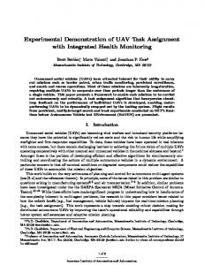
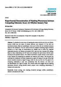
a splitting component that splits up the data on disjoint paths. In contrast to Equal-Cost Multi-Path (ECMP), the splitter is not bound to simple packet-wise load balancing but might be able to make use of knowledge on the structure of the transmitted data, i.e., video streams in our case. Finally, the multiple transmission paths end in an assembling component. Thereby, the assembler not only has to join but also needs to synchronize corresponding data streams by means of buffering and has to prevent reordering of packets [13]. Scalable Video Coding The H.264/SVC is an extension of the widely used H.264/Advanced Video Coding (AVC) codec, which was specified by the ITU-T [14]. SVC provides a way to shift the balance between quality and consumed bandwidth of an encoded video clip by selecting frame rate, resolution, and image quality. These three dimensions are called temporal, spatial, and quality scalabilities. Figure 3 illustrates a video containing all three scalabilities. Therein, the left “sub-cube” at the bottom is the base layer, which is necessary to play the video file at Common Intermediate Format (CIF) resolution, 15 Hz frame rate, and quality Q0. Based on this layer, different additional enhancement layers permit a better video experience with a higher resolution, better Signal-to-Noise Ratio (SNR), or higher frame rate. Enhancement layers can be omitted to reduce the required bandwidth without interrupting the video stream. However, their omission also decreases the video quality. As different layers are separately packeted, they can be sent via multiple paths. Cross-Layer Benefit As mentioned before SVC quality is assembled of different blocks, cf. Figure 3, that increase the quality of the video and also the required bandwidth. By means of NV, the VNO, which is given full control on the video transmission in our case, is able to make use of these SVC properties by splitting different quality layers among multiple paths. Thus, the service is able to make use of changes to the underlying VN. The ability to adapt both, network resources and service, has proven to outperform individual adaptations of either network or service. This is illustrated in Figure 4, which is computed based on the results taken from [15].
Data Plane
GMPLS Control Plane
Demonstration of Network Virtualization and Resource Flexibility Router OSPF-TE LMP
PCE
Agent VNO
multi-path SVC
Agent VNO Request path from PIP
RSVP-TE
Switching Element
7
Monitoring Server
Decision Component
Action
Fig. 5. GMPLS protocol stack and Fig. 6. Interaction of different roles and compocomponents. nents to an integrated architecture.
Investigations on the impact of the SVC scalabilities on the user perceived quality as well as the influence of insufficient network resources on SVC video streaming were published recently. In [16], the authors showed that spatial adaptation should be preferred compared to temporal adaptation. This results from spatial adaptation allowing higher bandwidth savings and lower decrease in video quality than temporal adaptation. Packet loss rates of about 2% already have a severe impact on the user perceived quality, as indicated by [17]. However, it was shown that packet loss on enhancement layers has a lesser impact on Quality of Experience (QoE) than packet loss on the base layer. Thus, we conclude that in case of multi-path video streaming with different path QoS parameters, the enhancement layers should be transmitted via the paths with lower QoS. 3.2 Monitoring To be able to react on increasing load, e.g., to change the topology of a VN and to split the SVC video stream to off-load paths, monitoring is required. In the considered scenario, performing monitoring solely by the VNO is sufficient since we presume trust between the roles and the VNO has full control on the video transmission. As we consider a distributed architecture, we require distributed measurement points. Thereby, data is collected by, so called, agents that send information to a data collection point, a database server. We use the StableNet software [18], which uses Simple Network Management Protocol (SNMP) amongst others for monitoring the state of network resources and provides interfaces to trigger decision making for certain network situations such as high load. Furthermore, StableNet is multi-tenant capable. This opens up the possibilities to use a single monitoring solution to individually monitor different ASPs or VNOs with a single StableNet server. 3.3 Control Plane Framework As presented in Section 2, a PIP has two core tasks. Firstly, a PIP operates and manages a physical network consisting of nodes and links. Secondly, a PIP creates virtual resources on top of the physical resources. In our demonstration, we focus on the virtualization of links. Due to the dynamic nature of virtual networks, we
8
Duelli, Meier, Wagner, Zinner, Schmid, Hoffmann, Kellerer
expect a PIP to rely on a control plane to automate virtual link management. This includes virtual link establishment, modification, and tear-down. Figure 5 depicts the functional blocks and protocols of the GMPLS framework [19] that are involved in virtual link setup. We will shortly introduce those components in the following. To verify whether a virtual link can be embedded into the physical network, a PIP needs an up-to-date view on its physical links, their properties, and their utilization. The Link Management Protocol (LMP) and in particular the Open Shortest Path First protocol with traffic engineering extensions (OSPF-TE) provide this information. Currently, Traffic Engineering (TE) extensions are defined for bandwidth information. Additional metrics such as link delay are currently taken into account by emerging protocol extensions [20]. Relevant information on resource usage is stored in a Traffic Engineering Database (TED). Algorithms for constraint-based path computation can operate on this TED to find possible embeddings of a virtual link into the physical network. Embedding can be a complex task, in particular for large networks and many constraints. Therefore, the GMPLS framework comprises a dedicated Path Computation Element (PCE) for constraint-based path computation. Once an embedding solution is computed, signaling protocols such as RSVPTE are used to instantiate the virtual link accordingly. In case of RSVP-TE, a hop-by-hop signaling is performed to allocate resources on each node that the virtual link traverses. During this setup every node verifies that the requested QoS parameters can be satisfied and reserves resources for the virtual link. 3.4 Integration The starting point for designing software integration in NV environments is the generic role interactions as depicted in Figure 2. Obviously, each role has access to monitoring information but on different levels: the PIP has access to all monitoring based on the physical devices while the VNO only gets information regarding its VN. This monitoring information defines the foundation of the decision making components of each player. These decision making components represent the players’ intelligence, their decisions are based on internal policies and strategies. Therefore, they also cannot be standardized or even predicted, so we decided to define the decisions to be taken beforehand. In the considered scenario, the decisions of the PIP concern where to place paths and Virtual Machines (VMs). The decisions of the VNO are the layout of the VN and the configuration of the VMs. In the selected use case, this includes where to install splitting and assembling functionalities, to configure the routing of the different video layers but also to dimension the links and nodes of this VN. An overview of the control process in the VNO is given in Figure 6.
Demonstration of Network Virtualization and Resource Flexibility
9
4 Demonstration We developed a sophisticated scenario to show the flexibility in service provisioning that can be achieved using the capabilities of an automated Network Virtualization Infrastructure and of a elaborated service provisioning architecture. We demonstrate automated network management and resource control for virtual networks in the use case of a high quality VoD service over virtual networks. This scenario was integrated in a real network and was demonstrated at EuroView 2011 [5]. In the following, the technical realization, the starting situation and the run of events are presented in detail. 4.1 Testbed The scenario has been implemented using seven off-the-shelf PCs running Ubuntu Linux 10.04 equipped with 4-port Gigabit Ethernet network interface cards. These nodes have been configured with distinct IPv4 networks for each link and a manually configured routing table. In order to separate data plane and control plane in the set-up, an additional GRE-tunnel [21, 22] was set up on each GMPLS-controlled physical link and provided with its own IPv4 addresses. Nevertheless, the data plane implementation is not complete: there are no labels added and there is no scheduling enforcing the confirmed bandwidth. Five of the seven nodes represent the PIP’s network infrastructure while the other two represent the neighboring PIPs hosting source and destinations of the video streaming service. Additionally, there is one remote machine hosting the StableNet server process representing the VNO’s service monitoring. Thus, there are seven local hosts in the testbed and one remote host representing three PIP domains and one VNO domain in total. 4.2 Starting Situation As a starting point the PIP in focus is assumed to have its physical components virtualized and offering them via the VNP to VNOs. The PIP already deployed virtual routers without special functionality within the network. An ASP has developed a business plan for a VoD service and requests the VNO to design the required network and to deliver the service. The VNO decides for a SVC solution as it provides the VNO with the most adaptable solution while transmitting the video. Based on this decision and the business plan of the ASP, the VNO plans the network for the assumed customer base. The network provided by the VNP includes a part provided by the PIP in focus. In Figure 7, the PIP’s topology can be seen in the upper right part of the demonstration GUI, which integrates the PIP’s and the VNO’s view for demonstration purposes. The PIP’s network consists of the ring formed by nodes A to E and the links in between. For the sake of clarity, we additionally depict the nodes and links that the PIP uses for peering, i.e., node G connecting to the data center and node F connecting to the users. To guarantee the QoE requested
10
Duelli, Meier, Wagner, Zinner, Schmid, Hoffmann, Kellerer
demo control GUI
topology of the PIPs (weathermap)
measurement of links A-B and A-E Fig. 7. Annotated illustration of the initial set-up of the VN.
by the ASP, the VNO monitors the virtual resources which is indicated in the lower part of Figure 7. The VNO is prepared to trigger actions with regard to the SVC set-up as well as by requesting changes to the VN from the VNP that communicates with the PIP. 4.3 Course of Events The VNP requests the PIP to create a VN consisting of a connection from node G to F with virtual nodes at the domain borders (nodes A and D). For the demo, we use a simple GUI element to trigger the request (visible on the middle left). After receiving the request, the PIP’s network management has to determine how to fulfill the request, which heavily depends on business policies and strategies. We define the path A-B-C-D as the selected solution. Having the request mapped to physical resources, the PIP triggers an RSVP-TE signaling session to set up the virtual link. In the demo, the signaling PATH and RESV messages establish a Label Switched Path (LSP) with the requested bandwidth as can be seen in Figure 7. When the signaling is complete, the VNO takes over control of the VN and sets up the VoD service. This includes setting up the streaming server in the data center, but also deploying monitoring agents in the VN. In this case, that
Demonstration of Network Virtualization and Resource Flexibility
11
Fig. 8. VoD service running and serving an increasing number of clients.
means StableNet agents on nodes B and E. The VNO’s monitoring shows the current usage of the requested virtual link from node A to D as depicted at the bottom of Figure 8. Since the PIP provides virtual resources for other VNs as well, resource usage on the physical infrastructure may change without changes in the selected VN. In our scenario, the remaining bandwidth of the link between nodes B and C is assigned to another VN indicated by a red line as shown in Figure 8. But also the resource consumption within the VN changes and may call for adaptation. In our scenario, more and more customers join the VoD service inducing an increasing bandwidth consumption, which we emulated by a traffic generator on node G. The VNO’s StableNet agents keep track of this as virtual link utilization is monitored constantly. At a predefined link utilization level of 75%, the StableNet monitoring issues a warning to the VNO, shown by the yellow background color in Figure 8. Due to the history of the link utilization the VNO’s network management system reacts. One possible reaction is a request to the VNP and then to the PIP to increase the bandwidth of the existing virtual link. As there is no remaining capacity on the link B-C, the PIP has to decline this request. However, the PIP may set up a second virtual path via node E although this path is known to have a higher packet loss probability than the first one. We therefore assume that these paths cannot be transparently aggregated. Nevertheless, the PIP offers the VNO to
12
Duelli, Meier, Wagner, Zinner, Schmid, Hoffmann, Kellerer
Fig. 9. Enhancement layers successfully transferred to second path.
adopt the VN by adding a second virtual path between nodes A and D with higher packet loss probability. When evaluating this offer the VNO has to consider the SLAs in force for this service. We assume that the VNO cannot simply serve new users using this second path due to the links’ characteristics and its service guarantees with the ASP. Nevertheless, due to the flexible SVC framework the VNO can maintain high QoE for all users despite the lower QoS characteristics of the second virtual path. As described in Section 3.1, packet loss on the base layer result in a higher impact on the perceived quality than on the enhancement layers, which may be separated and routed differently using this enhanced framework. Therefore, the VNO can configure its components to transmit the base layer for all users on the reliable path and the less important ones on the second path. So the VNO accepts the proposal of the PIP and activates a demuxer daemon on node A and a muxer daemon on node D. As a result there is no perceivable quality degradation of the video streams that are delivered to the customers. The resulting changes in traffic on the two paths are illustrated in the lower part of Figure 9.
5 Lessons Learned & Next Steps The process of integrating and setting up the scenario described in Section 4 provided insights on how interaction between different roles and also between functional components controlled by one role have to be designed. Anyway, this
Demonstration of Network Virtualization and Resource Flexibility
13
integration is just an intermediate step to an extended scenario that is to be designed, implemented, and integrated in the coming months. Both, lessons learned and next steps, are presented in the following. 5.1 Lessons Learned This section details the lessons learned during the implementation of the building blocks and their integration into the discussed demonstration scenario. Control Loop Coordination The experimentation provided us a holistic view on several phases of the operation of a selected VN. It revealed challenges as well as promising solutions. The most prominent lesson learned from the scenario is that possessing flexibility in network and service does pay off in certain scenarios. Moreover, it may pay off by various ways: when designing this scenario in order to use all capabilities of the Virtualization Platform and SVC, we found that many simpler scenarios, that would cause serious problems when using today’s network and service architecture, can be alleviated or significantly improved by each of the two actors (PIP and VNO) alone given either the advanced features of NV or SVC. This clearly highlights the challenge how these independently managed control loops can be coordinated in order to avoid redundant or contradicting actions and oscillation. VN Descriptions In order to establish such VN-provisioning relationship as presented in the scenario and to allow for automatic topology changes, description of VNs have to be exchanged in a negotiation process. These descriptions express requests or offers of VNs to be created or changes to existing VNs. The work on this topic is ongoing, some general requirements were identified. – Description methodology: The information model needs to support all needed network elements and has to support embedding of information on control access. – Negotiation protocol : Although a simple take-it-or-leave-it approach could be used, the flexibility often incorporated by complex topologies would be neglected and the solutions are expected to be far from optimal. – Definition of responsibilities. This depends on a solution for challenge described above but since all players do have capabilities to react to external events from the start, it would make sense to include agreements on responsibilities in the VN negotiations from the very beginning. Multi-Path SVC Streaming Multi-path transmission implemented in the network requires additional functional blocks, namely a flow splitter and a flow assembler. We implemented these functionalities and also mechanisms to cope with out-of-order packets and assure a valid byte stream for the video player. We used the capabilities of a SVC stream to split the flow into base and enhancement layers and transmit them via different paths. This extends pure round-robin packet scheduling techniques. However, we had to extend the flow assembler to be able to identify base and enhancement layers in order to reassemble the
14
Duelli, Meier, Wagner, Zinner, Schmid, Hoffmann, Kellerer
complete stream or forward only a part of the stream if parts are missing. Due to SVC dependencies we could not forward the video clip frame by frame but buffered a Group of Pictures (GOP) before we forwarded the best available video quality stream to the destination. Thus, we had to provide a larger buffer at the assembler compared to the case of round-robin packet scheduling. The splitter transmits packets via different paths and the assembler receives the packets and forwards them to the destination. In order to guarantee the original sequence of the packets, this entity has to buffer out-of-order packets and re-sequence the packets if necessary [12]. This introduces additional waiting times in the magnitude of the current round trip time. However, by tailoring multi-path transmission to work together with SVC streaming we had to care on additional issues. First, the splitter has to be able to identify base and enhancement layers and transmit them via different paths. This extends techniques like round-robin based scheduling approaches. In order to exploit the capabilities of SVC, the assembler also is able to identify the different quality layers. We took into account, that switches between resolutions can be performed on a GOP basis. Thus, we first assemble all parts of the current GOP, identify whether a quality switch was performed and then forward the best available video quality stream to the destination. 5.2 Next Steps The scenario presented in Section 4 shows flexibility and dynamic in terms of “breathing” of the VN and the service. Nevertheless, instantiated components remain at their physical host throughout the VN’s life time. But there are incentives for both the PIP and the VNO to relocate virtual resources. Motivations for the PIP to move a VM from one physical host to another range from utilization optimization, maintenance, data center migration, consolidation, or even disaster avoidance [23]. On virtualization level today a VM can be migrated without noticeable service interruption from one physical host to another (live migration) but these mechanisms are Ethernet and IPv4-focused and come with several constraints. The integration of VM-management with a virtualization-enabled network control plane, e.g. based on GMPLS, promises to ease live migration of VMs and to reduce constraints. The VNO itself may have motives to restructure its service provisioning VN by relocating resources, e.g., to cope with changed (technical) requirements that cannot be met at the old location or in order to save money by moving to another VNP. In any case, this approach needs service or application specific knowledge and possibly even built-in support. Therefore, the scenario can be extended by relocation of virtual resources by virtualization or application specific means. Another important topic to be addressed is the control loop coordination, in particular the cooperation of PIP and VNO. There are events that are evident from the infrastructure layer monitoring of the PIP, the network monitoring within the VN performed by the VNO as well as from the application level monitoring performed by the ASP. If such network situation changes happen and PIP and VNO and ASP use simple independent control mechanisms, they
Demonstration of Network Virtualization and Resource Flexibility
15
all might trigger reactions to this condition which might prove to be redundant or even contradicting. E.g., a link failure should normally just trigger the resilience mechanisms provided by the PIP. Anyway, if these mechanisms fail or do not exist, possibly the VNO could improve the situation by changing the VN-internal routing or even the ASP could reduce the currently needed bandwidth by servicespecific means. Thus, it is not only required to define responsibilities between the roles but also to develop means to coordinate them dynamically.
6 Conclusion In this paper, we presented a complete scenario using NV. It is based on a market model comprising PIPs, VNPs, VNOs and ASPs, defining a vertically and horizontally divided market. We presented our implementations namely an SVC framework, a GMPLS control plane, and a monitoring framework. For the selected use case of VoD delivery using a VN, the scenario shows the variety and power of interaction between different roles. In the scenario, the cooperation of the PIP and the VNO, i.e., coordination of virtualization and service layer, guarantee unaffected QoE for the end-users despite of unexpected demand and limited network resources. One prerequisite for successful coordination is an efficient monitoring infrastructure that allows to react on changing conditions as well as to verify SLA accordance of consumed and provided services. The second prerequisite is an ability to handle the dynamic of each player in its own responsibility domain: the PIP has to be able to adapt instantiated VNs as well as a VNO should be able to adapt its service to changing demands. A future challenge is the coordination of these independent but overlapping control loops. In short, we showed that NV is able to bring benefits for all parties but the coordination of the different control loops needs to be further investigated.
References 1. N. Chowdhury and R. Boutaba, “Network virtualization: state of the art and research challenges,” Communications Magazine, IEEE, vol. 47, pp. 20 –26, july 2009. 2. German-Lab (G-Lab), Project Web Page, Dec. 2011. http://www.german-lab.de. 3. COntrol and Management of COexisting Networks (COMCON), Project Web Page, Dec. 2011. http://www.german-lab.de/phase-2/comcon/. 4. S. Meier, M. Barisch, A. Kirst¨ adter, D. Schlosser, M. Duelli, M. Jarschel, T. Hoßfeld, K. Hoffmann, M. Hoffmann, W. Kellerer, A. Khan, D. Jurca, and K. Kozu, “Provisioning and Operation of Virtual Networks,” Electronic Communications of the EASST, Kommunikation in Verteilten Systemen, vol. 37, Mar. 2011. 5. D. Schlosser, M. Duelli, T. Zinner, S. Meier, D. Wagner, M. Barisch, M. Hoffmann, W. Kellerer, and M. Schmid, “Service Component Mobility Enabled by Network Virtualization,” in EuroView 2011, (W¨ urzburg, Germany), Aug. 2011.
16
Duelli, Meier, Wagner, Zinner, Schmid, Hoffmann, Kellerer
6. N. Feamster, L. Gao, and J. Rexford, “How To Lease The Internet In Your Spare Time,” SIGCOMM Comput. Commun. Rev., vol. 37, no. 1, pp. 61–64, 2007. 7. R. Bless and C. Werle, “Network virtualization from a signaling perspective,” IEEE International Conference on Communications Workshops, pp. 1–6, June 2009. 8. Y. Cheng, R. Farha, A. Tizghadam, M. S. Kim, M. Hashemi, A. Leon-Garcia, and J.-K. Hong, “Virtual network approach to scalable ip service deployment and efficient resource management,” Communications Magazine, IEEE, vol. 43, no. 10, pp. 76 – 84, 2005. 9. X. Yang et al., “Policy-based resource management and service provisioning in gmpls networks,” in In First IEEE Workshop on Adaptive Policy-based Management in Network Management and Control, 2006. 10. S. Figuerola, J. A. Garc´ıa-Esp´ın, and J. F. Riera, “An optical network and it infrastructure virtualisation framework from geysers project.” Local event in Catalonia, 2010. 11. Generalized Architecture for Dynamic Infrastructure Services (GEYSERS), Project Web Page, Dec. 2011. http://www.geysers.eu. 12. T. Zinner, K. Tutschku, A. Nakao, and P. Tran-Gia, “Using Concurrent Multipath Transmission for Transport Virtualization: Analyzing Path Selection,” in Proceedings of the 22nd International Teletraffic Congress (ITC), (Amsterdam, Netherlands), Sept. 2010. 13. T. Zinner, D. Klein, K. Tutschku, T. Zseby, P. Tran-Gia, and Y. Shavitt, “Performance of Concurrent Multipath Transmissions - Measurements and Model Validation,” in Proceedings of the 7th Conference on Next Generation Internet Networks (NGI), (Kaiserslautern, Germany), June 2011. 14. ITU-T Recommendation, “H.264 : Advanced video coding for generic audiovisual services.” http://www.itu.int/rec/T-REC-H.264. 15. T. Hoßfeld, M. Fiedler, and T. Zinner, “The QoE Provisioning-Delivery-Hysteresis and Its Importance for Service Provisioning in the Future Internet,” in Proceedings of the 7th Conference on Next Generation Internet Networks (NGI), (Kaiserslautern, Germany), June 2011. 16. T. Zinner, O. Hohlfeld, O. Abboud, and T. Hoßfeld, “Impact of Frame Rate and Resolution on Objective QoE Metrics,” in International Workshop on Quality of Multimedia Experience, (Trondheim), June 2010. 17. K. D. Singh, A. Ksentini, and B. Marienval, “Quality of Experience Measurement Tool for SVC Video Coding,” in IEEE International Conference on Communications (ICC), (Kyoto, Japan), pp. 1–5, June 2011. 18. Infosim, StableNet, Dec. 2011. http://www.infosim.net/index.php/products. 19. E. Mannie, “Generalized Multi-Protocol Label Switching (GMPLS) Architecture.” RFC 3945 (Proposed Standard), Oct. 2004. Updated by RFC 6002. 20. X. Fu, M. Betts, Q. Wang, D. McDysan, and A. Malis, “GMPLS extensions to communicate latency as a traffic engineering performance metric.” draft-wangccamp-latency-te-metric-03 (Proposed Standard), 2011. 21. S. Hanks, T. Li, D. Farinacci, and P. Traina, “Generic Routing Encapsulation (GRE).” RFC 1701 (Informational), Oct. 1994. 22. S. Hanks, T. Li, D. Farinacci, and P. Traina, “Generic Routing Encapsulation over IPv4 networks.” RFC 1702 (Informational), Oct. 1994. 23. Joint whitepaper from VMware and Cisco, Virtual Machine Mobility with VMware VMotion and Cisco Data Center Interconnect Technologies, 2009. http://www.cisco.com/en/US/solutions/collateral/ns340/ns517/ ns224/ns836/white_paper_c11-557822.pdf.