been recognized by the utility companies, computer ... load that can efficiently substitute imported brands of the same rating ... Computer/Laptop 200. 2. 400.
SSRG International Journal of Electrical and Electronics Engineering (SSRG-IJEEE) – volume 2 Issue 7 July 2015
Experimental Design of a 1.5KVA UPS Unit Using Locally Obtainable Materials under Prevailing Academic Laboratory Condition in Nigeria A.I. Arowolo#1, I.O. Animasahun*2, A.O. Melodi#3 #1
Teaching Assistant,#2Assistant Lecturer, #3Associate Professor& Departmentof Electrical / Electronics Engineering & Federal University of Technology Akure. P.M.B.704, Akure, Ondo State, Nigeria.
Abstract—This study is aimed at designing, fabrication and evaluation of an efficient UPS based on locally obtainable material and conditions, for local application in academic environments. From a load survey, a load of 1.2 kW was obtained for Nigeria academics offices, which lead to the design of a 1.5 kVA UPS. A standard oscillating circuit based on CD4047 was adopted and adapted in the design. By loading requirements, 8 units of IRF250 MOSFETs were evaluated for the design. To improve the reliability (increase time to failure of battery) and effectiveness of the design, a battery charging controller and level detector were evaluated for addition to the design. The oscillatory circuit was tested using oscilloscope, and the open circuit and short circuit tests of the designed transformer for the construction was carried to define its efficiency. From the design, a square waveform of output voltage was obtained. The designed transformer efficiency obtained for the designed UPS is approximately 82%. A comparative technical and costs assessment show that the constructed UPS is cheaper but of less efficiency when compared with the imported 1.5 kVA products available in the Nigerian market.
Keywords—UPS, Efficiency, Cost, Local Design, Office Load, Nigeria.
I. INTRODUCTION There are economic, social, technical and environmental challenges in trying to satisfy the demand of electricity by consumers in a developing economy. Alternating current power problems have been recognized by the utility companies, computer manufacturers and end users as a subject that must be addressed. The power problems extend from spikes, noiseand frequency variations to complete black-outs. These problems can be corrected individually using surge suppressors, filters, regulators, and amplifiers, but only Uninterruptible Power System (UPS) can solve all these problems collectively [1]. The UPS is a unitcomposing of a range of solid-state devices, are interconnected based on their respective functional principles to provide required unit function of protection against supply aberrations and failure for the critical. Because these units are composed of solidstate devices they are often described as static UPS units, as opposed to rotary systems which are based on motor/generator technology[2]. An UPS typically does two things[3]: It either provides power to enable the safe shutdown ofequipment and saving data to a non-volatile
ISSN: 2348 – 8379
medium, or it provides power to equipment overthe duration of mains fault/failure, enabling equipment to operate continuously.Continuous operation is primarily a function of loaddrawn and battery type and size.Basically, an UPS unit converts some or all of the AC power from the mains into DC for storage in a battery and thenback into AC power for the load when there is mains failure. This double conversion has many variations; however, all of the existing designs incorporate an inverter to convert DC into AC. It is the inverter operation which definesan UPS as on-line (operates only when needed) or off-line (operates continuously) [3]. The study is motivated by the unbearable discomfort to productivity and cost of power interruption in Nigeria academic environment where the availability of power supply is needed at all times. The local market is fully of numerous imported UPS devices with no local content or brands. Experimental studies for local brands are therefore crucial economically to Nigerian power supply conditions and reduction in dependence on imported brands. The aim of this study is to obtain a locally made UPS system that can cover a 1.5 kVA academic office load that can efficiently substitute imported brands of the same rating within Nigeria. The specific aims are to design and construct the UPS system under prevailing local laboratory conditions for comparative analysis with available imported brands in terms of cost and energy efficiency only.
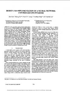
II. OPERATION PRINCIPLE OF AN UNINTERRUPTIBLE POWER SUPPLY SYSTEM The principle of operation uninterruptible power supply system depends on whether the UPS is off-line or on-line. It is off-line when the UPS operates only when needed and then it is on-line, when it operates continuously [4]. The one adopted in the design was the off-line or stand- by mode The Stand by UPS technology is shown in Fig. 1. The utility power in the off-line mode feeds the loadand the disconnect switch (solid state or electro-mechanical) is connected directly to the load. The Charger is on, keeping the battery under charge. During this stage, the Inverter is off and no voltage or frequency regulation for 4 to 10 millisecond transfer time (with break on the output). This is simple and reliable, cost-effective performance
www.internationaljournalssrg.org
Page 1
SSRG International Journal of Electrical and Electronics Engineering (SSRG-IJEEE) – volume 2 Issue 7 July 2015
and suitable for protecting workstations. The major drawbacks are: impractical above 2.2 kVA, unsuitable for industrial or extreme environmentsor where poor voltage regulation is present, and heavy above 500 VA. The block diagram for the UPS components is shown in Fig. 2.
shut down (if continued to be used), while the alarm circuit serves as an sound indicator when power supply is ‘ON’ and ‘OFF’ and also when the battery start its backup [4]. III. METHODOLOGY As earlier discussed, a UPS design is made-up of different stages. The design process of each stage is discussed in this section. A. Selection of the UPS Rating From a load survey of academic offices in a Nigerian Federal University, typical electric appliances (EAs) and quantities (Qty) were obtained for UPS unit sizing as shown in Table 1. The rating of the UPS was based on the chosen area of application, which is an office in an academic environment.
Fig. 1 The Standby/ off-line UPS LOW BATTERY INDICATOR &ALARM STAGES
Table I CONTROL AND OSCILLATION STAGE 12 V BATTERY
INVERTER STAGE
CHANGEOVER STAGE
BATTERY CHARGING STAGE
OUTPUT MAINS
T Y T t t EAs t T
Total Load Specification for the Office
Unit Load(W)
Fig. 2The block diagram of the UPS System
From Figure 1, when the UPS system is on off-line mode of operation, the above block diagram above indicates the flows of operation. The utility main supplies the battery charger stage as well as the load from the output end when the main is on. And when the main is off, the battery supply 12V to the inverting stage which is responsible for the conversion of D.C voltage to A.C voltage. It consists of power switching devices which are as follows: MOSFET, resistors, diodes. This is driven by control circuity of the control stage. The output from each half circuit of the inverter is connected to a center-tap transformer that commutates the output voltage and steps it up to the required mains voltage. The oscillatory stage is responsible for control of the switching’s devices in the inverter stage. It generate out of phase pulse trains to drive the MOSFET switches in the inverter stage. It also determines the frequency of operation i.e. the frequency of the output waveform from the inverter transformer. To ensure the automation of the change in supply from either the main to the battery or vice versa, the changeover stage which is comprises of relays is used with several sets of contact to perform the changeover function. The relay is enabled (energized) by the presence of mains voltage. The Low battery indicator circuit and alarm circuit provide visual indication of low battery level. An LED serves as the indicating devices. It comes ‘ON’ at a predetermined battery voltage level before the UPS
ISSN: 2348 – 8379
EA Television Set Computer/Laptop Printer Fan Florescent Tube Miscellaneous Total
PU 100 200 200 80 60 100 740
Qty of EA NU 1 2 1 2 4 1 11
Total Load(W) PEA 100 400 200 160 240 100 1200
The UPS capacity rating can be obtained from the equation .1 [5]:
Using a power factor of 0.8[6], The miscellaneous rating in the table above caters for additional rating that may be needed. B. Oscillation stage For the oscillation stage, 4047 integrated circuit(IC) was used. It generates a square wave and this determines the frequency of the pulse at the output of the oscillator. This will only be achieved when connected with some external components such as capacitors, resistors, 7812 and 7815 regulators and transistors [7] as shown in fig. 3.
www.internationaljournalssrg.org
Page 2
SSRG International Journal of Electrical and Electronics Engineering (SSRG-IJEEE) – volume 2 Issue 7 July 2015
Each of the MOSFET was mounted on a heat sink in order to keep the temperature of the semi-conductor below 1250C [10]. To calculate the required thermal resistance of the heat sink, equation 4[10] was used. 4 where, TJ is the junction temperature and T C is the case temperature. Tj = 125oC, Tc =25oC [10] D. Battery charging stage and battery level detector
Fig.3 CD4047 Circuit Layout
From CD4047 data sheet [7], the maximum capacitance that can used in the layout is 50pF at 200kΩ, therefore a capacitor (C2) of value 0.1μF was used. A frequency of 50Hz was chosen as the pulse frequency owning to the fact that the expected sine wave frequency will be 50Hz. The relationship between the capacitor and the resistor is given by the equation 2 [7].
The circuit layout of the battery charging is shown in figure 5. Transformer T1steps down the mains voltage from 240V to 12V. The 12V A.C voltage from the transformer is passed through a power bridge rectifier D1-D4to provide full rectification. Power resistor R1 helps to limit the charging current to a safe value and diodes D6 prevents the battery from discharging back into the bridge rectifier and the transformer during mains failure. This also helps to avoid the LED becoming lit.
2 where, T is the period and hence, the resistor value (R1) can now be calculated to be 50kΩ. C. Inverter/Diver stage The driver used for this project is MOSFET based due to the fact that it does not suffer from thermal breakdown and majorly it aids paralleling since it has a positive on-resistance unlike bipolar transistor which will require a current equalising resistor [8]. MOSFET (IRF250) was used for the design, paired in parallel as shown in figure 4 to ensure a maximum power transfer. Equation 3 [9] was used to calculate the number of MOSFET required. 3 where IRF250 maximum power dissipation is 150W , .
Fig.5 Battery Charging Circuit
LTC 4060 which serve as the charger control automatically senses the DC input supply and battery insertion or removal. Heavily discharged batteries are initially charged at C/5(battery capacity per 5hours) rate before a fast charge is applied. Fast charge is terminated using the –∆V detection method[11]. Backup termination consists of a programmable timer and battery overvoltage detector. The battery level detector employs the use of LM324 output comparator IC which compares the battery voltage with a reference voltage at different levels and produces their corresponding output which energizes the Light emitting diode (LED) to show the battery level. It consists of four operation amplifiers which acts as a follower circuit with all the inverting pins gated with 1k and then grounded. In this design, the four voltage levels are indicated by four light LED in a vertical array listed in Table 2. Table II Led Indicators
Fig. 4 MOSFET Paralleling Circuit.
ISSN: 2348 – 8379
VOLTAGE LEVEL HIGH MEDIUM LOW SHUT DOWN
LED INDICATOR RED GREEN YELLOW WHITE
www.internationaljournalssrg.org
Page 3
SSRG International Journal of Electrical and Electronics Engineering (SSRG-IJEEE) – volume 2 Issue 7 July 2015
E. Changeover stage The changeover stage was designed for automatic control of its mechanism with the aid of a relay. The relay used for this design is FANGKE JZC- 23F (4123) with specification given as 10A/28Vdc, 2.8 Ω, dc 12V. In this design, five relays of 12 V were used. F. Transform Design 1) Design Requirement The transformer requirements used to step up the battery voltage from 12V to 220V were calculated based on the UPS rating. These are then summarised in the Table 3. Table III The Transformer Requirements
Transformer Requirement Primary Voltage Secondary Voltage
Calculated Value 12V 220V
Primary current Secondary current
125A 682A
Primary winding wire gauge Secondary winding wire gauge
SWG12 SWG22
Number of secondary turns
504 turns
Number of Primary turns
28turns
The range of theMarket Cost of Imported Cm for a 1.5kVA rated UPS according to [12] is from ₦ 12,000 - ₦ 15,000. The cost of the constructed UPS is ₦ 10,000. The cost comparison factor (β) is given as, 9 where, is the market maximum cost, is the cost of the constructed UPS, is the market minimum cost, and is the minimum and maximum difference in cost between imported and constructed UPS. The obtained values of , and is shown in Table 6. IV. RESULT AND DISCUSSION A. Experimental Results and Discussion
2) Transformer efficiency The total loss in a transformer is given as 5 [5] 5 where is the iron loss, and is the copper loss. The values of and were obtained from open circuit and short circuit tests respectively. The Efficiency ( ) of transformer is obtained as,
where
where, is the market maximum efficiency, is the efficiency of the constructed UPS, is the market minimum efficiency, and is the minimum and maximum difference in efficiencies between imported and constructed UPS. The obtained values of , and is shown in Table 5. 2) Comparison in term of cost
Test was carried out on each stage of the inverter. The oscillator stage and the inverting stage were tested using an oscilloscope and their results are shown in fig. 6.
6 is the input power to the UPS.
7 where and are the input voltage and current to the UPS respectively. The obtained values of are presentedin Table 4. G. Comparative efficiency and cost analysis The constructed UPS was compared with existing UPS of the same rating in Nigeria market. The comparison was carried out in terms of efficiencies and costs of the UPS. 1) Comparison in term of efficiencies The range of the market efficiency (ζm) for a 1.5kVA rated UPS according to [12] is from 95% to 99%. The efficiency of the constructed UPS as shown in table 4 is 82%. The efficiency comparison factor (α) is given as,
(a)
(b)
Fig. 6Results from the oscilloscope
The output from an oscillator, shown in fig. 6a is a square wave which is produced by the astable mode in the oscillator. This is needed in order to get the equivalent sine wave shown in fig. 6b. The conversion of the sine wave was carried out by the inverting stage of the system which consists of four pair of MOSFET. Table 4 presents the result obtained the short circuit test and open circuit test carried out on the constructed transformer. The result shows an efficiency of 82%, obtained from calculation.
8
ISSN: 2348 – 8379
www.internationaljournalssrg.org
Page 4
SSRG International Journal of Electrical and Electronics Engineering (SSRG-IJEEE) – volume 2 Issue 7 July 2015
Table IV Transformer Test and Efficiency Result
( W) 20.8
( W) 200
( W) 220.8
( V) 220
( A) 5.45
( W) 1200
% 8 2
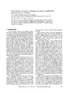
Fig. 7 shows the relationship between the copper loss and the input voltage obtained when the short circuit test setup input voltage was varied. From the graph, it was observed that the minimum loss is at 20V. This then suggests that the input voltage must be above 20V.
be 82%, and from a comparative analysis in terms of cost and efficiencies between imported UPS in Nigeria market and the constructed UPS using the proposed metrics of and , it was observed that the imported UPS is of higher efficiency than the constructed UPS by 14 to 17%, but also costlier than the constructed UPS by 17 to 33%. From the comparison results, it can be implied that the differences in the efficiencies can be compensated for if the laboratory condition of the constructed UPS is improved upon to be of the same or better condition as that of the imported UPS. Acknowledgment I wish to acknowledge the contribution of the laboratory staff of the Department of Electrical/Electronics Engineering, Federal University of Technology Akure, for their support and advice during construction and testing of the design. And also friends and colleague for their critical look at the work. REFERENCES
Fig. 7 The Relationship between the Copper Loss and the Input Voltage Table V Result of comparison in terms of efficiency
(
( %) 95
%) 99
(% ) 82
(
( %) 17
%) 13
0.1 4 to 0.1 7
Table VI Result of comparison in terms of cost
( ₦) 12,000
( ₦) 15,000
(₦ ) 10,00 0
₦) 2,000
(
₦) 5,000
( 0.16 7 to 0.33 3
From Table 5, the value of α obtained implies that the efficiency of imported UPS in Nigeria market is greater than the constructed one by approximately 14 to 17%. Also from table 6, the value of β obtained indicates that the imported UPS are costlier than the locally constructed UPS by approximately 17 to 33%.
[1]A.B.C Training Manual (2002) UPS Theory.[Online]. Available:http://www.batterycare.co.uk/techdocs/Chapter%205%20 UPS%20Theory.pdf [2]O.I.Okoro,‘‘Nigeria Power Sector Reforms in NigeriaOpportunities and Challenges’’, thesis, University of Nigeria, Nsukka, Nigeria, pp. 1-3, 2006. [3] NASA (2006), ‘‘Uninterruptable Power SupplySystems (UPS) ’’, pp. 2, 5. [4] Preferred Practices, ‘‘Uninterruptible Power Supply Systems (UPS)’’, Practice no. GSE3008, pp. 3-4, 2006 [5]M.B.L Theraja andA.K Theraja, Electrical Technology,Scand &company Ltd., India, pp.1145- 1147, p 2408, and pp. 2429-2730, 2005. [6] White paper (2002) Experts speak on UPS Output Watt, VA, and Power Factor ratings. American Power Conversion pp. 1-7 [Online]. Available: hptt//:www.ptsdcs.com/whitepapers,. [7] Fairchild (2002) D4047BC Low Power Monostable and Astable Multivibrator. [Online].available: http//:www.fairchildsemi.com, pp.1-9. [8] S. Abdus and T. Vledimir,(2007), MOSFET Withstand Stress of Linear Mode Operation, Power Electronic Technology, available at www.powerelectronics.com, p.36. [9] IRF250 Data Sheet (1999) IRF250 Power MOSFET. [Online]. Available: http://www.intersil.com,pp. 1-7. [10]P.E Jonathan, Advanced Power Technology, Columbia StreetBend, OR 97702, pp.1-4, 40, 2006. [11] F. Hoffar, ‘‘Linear Charger for Nickel Cadmium or Nickel Metal Hydride Batteries Minimizes Parts Count’’, Linear Technology Magazine, Vol. 15, pp.35-37, 2005. [12] Blessing computes (2014) UPS homepage on Blessing Computers.[Online].Available:hptt//:www.blessingcomputers.com/s /accessories/power/ups/1?
V. CONCLUSION The Uninterruptible Power Supply of 1.5kVA, 1.2kW, 12V was designed for application as a backup power source for a typical load in an academic office using locally available materials and under academic laboratory condition. The design procedure in each stage of the UPS was well presented in detail. The efficiency of the designed transformer was obtained to
ISSN: 2348 – 8379
www.internationaljournalssrg.org
Page 5