International Journal of Computer Applications (0975 – 8887) Volume 128 – No.6, October 2015
Power Efficient Arithmetic Logic Unit Design using Reversible Logic Naman Sharma
Rajat Sachdeva
Upanshu Saraswat
Bharati Vidyapeeth’s College of Engineering, New Delhi-110063
Bharati Vidyapeeth’s College of Engineering, New Delhi-110063
Bharati Vidyapeeth’s College of Engineering, New Delhi-110063
Rajat Yadav
Gunjeet Kaur
Bharati Vidyapeeth’s College of Engineering, New Delhi-110063
Bharati Vidyapeeth’s College of Engineering, New Delhi-110063
ABSTRACT Reversible logic is highly useful in nanotechnology, low power design and quantum computing. The paper proposes a power efficient design of an ALU, using Reversible Logic Gates. With power management becoming a critical component for hardware design developers, Reversible Logic can provide a viable alternative towards creating low power digital circuits.
Keywords Reversible logic, Arithmetic Logic Unit, Low Power Design
General Terms Power Efficient Digital Logic Design
1. INTRODUCTION The recent advancements in the field of Large Scale Integration, especially over the last ten years have enabled engineers to create new, more powerful devices than ever before. The technology has become ever more portable, personalized and has tremendous built-in functionality. This is the era of smartphone and portable computers. With the size of the chip being reduced, power consumption has become the paramount concern during design considerations. Many techniques such as voltage scaling, to reduce the power consumption of circuits are suggested but their use results in incremental improvements only [11]. It is predicted that the Moore‟s law is at an end due to the inability of the designers to keep up with the power requirements of the future chips. [1] One of the solutions to meet the low-power requirement of the future devices is by adopting an entirely new model known as Reversible Logic. Reversible logic finds its origins in the concepts of Quantum Computing [12]. Researchers like Bennett showed that the devices based on reversible computing consume much less power than the traditional irreversible devices [3, 4]. Reversible logic gates use one-toone mapping between input and output vectors, thereby preventing loss of information, which in turn prevents dissipation of energy, as shown by Landauer [5, 6]. Different arithmetic circuits such as Adders, Subtracters, Multipliers, Carry Adders etc. based on reversible are available in literature. Toffoli demonstrated in [14] that reversible logic structures are satisfactory for design and implementation in computing structures and organization when those design rules ensure the logic structure is invertible. Deustch later stated that reversible gates connected to each other by means of unit wires can be sufficiently used for the generation of a
quantum computational network [15, 16]. Quantum (reversible) gates are the generalization of classical logic gates. Deustch defined a source bit of „0‟ or „1‟ as a gate which, once every computational step, produces a value of „0‟ or „1‟ on its output [16]. In this paper, the authors propose an architecture for power efficient Arithmetic Logic Unit circuits using Reversible Gates. The paper first briefly provides an overview of the reversibe logic and few reversible gates in section 2. Thereafter, the architecture to implement the aforementioned ALU is proposed in section 3. The correctness of the proposed architectures is demonstrated through functional verification and performance analysis in Verilog in section 4. Finally section 5 concludes the paper.
2. BASIC REVERSIBLE GATES In 1960, researcher R. Landauer demonstrated that circuits using irreversible hardware results in energy dissipation of kTln2 Joules due to one bit loss of information where k is Boltzmann‟s constant and T the absolute temperature [5, 6]. Bennett showed that this energy loss can be avoided by constructing circuits using reversible logic gates [3, 4]. A reversible logic gate is an n-input, n-output logic function that maintains a one-to-one mapping between the two. Based on this principle, different basic reversible gates such as Feynman [7], Toffoli [8] and Peres [10] have been proposed. A 2*2 Feynman gate with inputs (A,B) produces the output P equal to input A while output Q as the XOR of the inputs [21]. A 3*3 Toffoli gate with inputs (A, B, C) and outputs (P, Q, R). It has outputs P and Q equal to A and B respectively while the output R is complement of the input C if both A and B are at logic 1, otherwise it is input C [21, 22] . A Fredkin gate is a 3*3 gate with inputs A, B and C giving outputs P, Q and R. The outputs are defined as P = A; Q= A‟B + AC; and R= AB + A‟C [23]. A Peres gate is a 3*3 reversible gate with inputs (A, B, C) and outputs (P, Q, R). The output P is equal to A; output Q is the XOR of A and B while R is complement of the input C if both A and B are equal to 1, otherwise it is equal to input C [24]. A URG gate is a 3*3 gate with inputs (A, B, C) and outputs P= (A+B) xor C, Q= B, R = AB xor C [21]. A PFAG gate is also known as a Peres Full Adder Gate. It is a 4*4 gate with inputs (A, B, C, D) and outputs (P, Q, R, S). The outputs take the values P=A; Q= A xor B; R = A xor B xor C and R= ((A xor B) C) + (AB) as described by Islam [17].
36
International Journal of Computer Applications (0975 – 8887) Volume 128 – No.6, October 2015
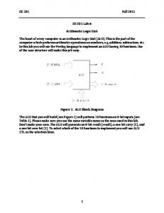
3. ARITHMETIC LOGIC UNIT USING REVERSIBLE GATES 3.1 Arithmetic Unit using Reversible Gates The arithmetic unit is the most fundamental building block of any digital system. It has the ability to perform basic arithmetic manipulation like addition, subtraction, addition with carry and subtraction with borrow on bits of data stored in registers. These manipulations are known as Microoperations [19]. The micro-operations which are used to cause data manipulation can be of four types – Register Transfer, Arithmetic, Logical, and Shift. An ALU primarily implements Arithmetic, Logic and Register Transfer microoperations. Hence the part of a digital circuit that causes arithmetic processing of data stored in registers is called an Arithmetic Unit. An arithmetic unit, in its implantation makes use of the basic full adder circuit. A full adder circuit can be implemented using reversible gates in many ways. Two of the easiest methods however, is by the use of two Peres Gate (PG) or by using a Peres Full Adder Gate (PFAG) as suggested by Islam [17]. The two methods have been shown below.
In the above figure, A = S0‟I0 + S0I1 (1) B = S0‟I2 + S0I3 (2) Y = S1‟S0‟I0 + S1‟S0I1 + S1S0‟I2 + S1S0I3
(3)
Using the above described elements, namely the Full Adder and the Multiplexer, one can fully implement the Arithmetic Unit. The following block diagram shows how this can be accomplished.
Fig 4: Block Diagram Showing the implementation of an Arithmetic Unit
Fig 1: 1-Bit Full Adder using two Peres Gates
The authors have therefore proposed the design of an arithmetic unit for which either of the two Full Adder designs may be used. The most optimized form of the circuit has been discussed later in the paper. The authors would also like to draw the reader‟s attention to the fact that further optimizations may be performed for the adder as well as the multiplexer circuit, which can yield better quantum cost, lower gate count or lesser garbage outputs.
3.2 Logic Unit using Reversible Gates
Fig 2: 1-Bit Full Adder using a single PFAG Gate The above given circuits provide two distinct implementations for one-bit Full Adder circuit. These 1-Bit implementations can be made for additional number of bits, (say 4 Bit) using a Serial Adder. The other crucial component required for the design of an Arithmetic Unit, is a Multiplexer. Here, the authors have used the simplest multiplexer design available in the literature; that is by making use of three Fredkin Gates (FG) [21]. The circuit diagram for a multiplexer has been given below.
The next design, required to implement an ALU is the Logic Unit. It is that part of the ALU which is used to perform bitwise logical micro-operations. The proposed Logic Unit can perform logical AND, OR, NOT and XOR operations. This was proposed using two architectures. The first architecture made use of a single 3X3 Peres Gate (PG) and a single 3X3 Toffoli Gate (TG) used along with a 4X1 Multiplexer circuit. The Multiplexer Circuit used here makes use of the same three Fredkin Gate implementation that has been discussed before. The first proposed architecture is given as.
Fig 5: 1-Bit Logic Unit using a combination of Peres Gate and Toffoli Gate In the next proposed implementation, the authors make use of a 3X3 Universal Reversible Gate (URG) used alongside a basic 2X2 Feynman Gate (FnG) along with the three Fredkin Gate Multiplexer used previously. The proposed architecture for this Logic Unit is given by. Fig 3: 4X1 Multiplexer Design using three Fredkin Gates
37
International Journal of Computer Applications (0975 – 8887) Volume 128 – No.6, October 2015
Fig 6: 1-Bit Logic Unit using URG and Feynman Gates The equation for O in both the circuits is defined as, O = S1‟S0‟I0 + S1‟S0I1 + S1S0‟I2 + S1S0I3 where, I0 = A + B … (4) I1 = A . B … (5) I3 = NOT A … (6) I4 = A B …(7) Hence either of the two implementations can be used to produce a Logic Circuit. With both the Arithmetic and the Logic Unit implemented, onecan now look at the implementation of the ALU.
Fig 7: Block Diagram for any Arithmetic Logic Unit One observes that the given implementation requires the use of a 2X1 Multiplexer. This can be easily implemented by making use of a single 3X3 Fredkin Gate.
3.3 ALU design using Reversible Gates The designs that have been suggested to implement 1-Bit Arithmetic Unit and 1-Bit Logic Unit are utilized to create an ALU. The proposed ALU will perform the following Microoperations. [18] Table 1: Functional Table for Arithmetic Logic Unit Fig 8: Implementation of a 2X1 Multiplexer using a single Fredkin Gate The authors have proposed two architectures for arithmetic logic unit using reversible gates. The first architecture makes use of the Peres Full Adder Gate (PFAG) for its Arithmetic Unit and uses a combination of Universal Reversible Gate (URG) and Feynman Gate (FnG) in the implementation of its Logic Unit. The second architecture uses two Peres Gates (PG) connected together for its Arithmetic Unit and uses a combination of Peres Gate (PG) and Toffoli Gate (TG) to implement the Logic Unit. These designs are shown below.
The interfacing of the Arithmetic Unit and Logic Unit in order to get an ALU can be described from the given block diagram.
38
International Journal of Computer Applications (0975 – 8887) Volume 128 – No.6, October 2015
Fig 9: Proposed Architecture for an Aritmetic Logic Unit (Architecture 1) implemented by using Fredkin, Universal Reversible, Feynman, and Peres Full Adder Gate
Fig 10: Prosposed Architecture for an Arithmetic Logic Unit (Architecture 2) implemented by using Fredkin, Peres and Toffoli Gates
4. SIMULATION SECTION This section first verifies the functionality of the proposed architectures (Arch-1 and Arch-2) to implement an ALU The functionality has been verified through Verilog Simulation. Waveforms for the various micro-operations were generated, and verified. Thereafter, the effectiveness of the proposed architecture is demonstrated through their synthesis on FPGA using Xilinx. The synthesis report generated has also been included by the authors in their findings.
Fig 12: Waveform analysis for the Addition with Carry Operation
4.1 Functional Verification This section includes the functional verification for architecture correctness. Waveforms generated for testing the correctness have been shown below.
Fig 12: Waveform analysis for the Subtraction with Borrow Operation
Fig 11: Waveform analysis for the Addition Operation Fig 12: Waveform analysis for the Subtraction Operation
39
International Journal of Computer Applications (0975 – 8887) Volume 128 – No.6, October 2015
input of the subsequent reversible gates. The quantum cost refers to the cost of the circuit in terms of a primitive gate. It is calculated knowing the number of primitive reversible logic gates (1*1 or 2*2) required to realize the circuit. [20] The comparative analysis is listed Table 2. Fig 12: Waveform analysis for the Increment A Operation
Fig 12: Waveform analysis for the Decrement A Operation
Fig 12: Waveform analysis for the Transfer A Operation
Fig 12: Waveform analysis for the Bitwise AND Operation
Table 2: Comparative Analysis of the Proposed Architectures
5. CONCLUSION The use of reversible logic and reversible logic based technologies is a promising choice for creating computational devices in the future. With quantum computing using Reversible Logic as the building blocks for the future computers, one can safely assume that such technologies will be critical in the near future. These circuits provide effective, power efficient alternatives to the modern day digital computers. They also provide significantly less number of garbage outputs as compared to other digital circuits. These designs can be further optimized to make them more powerful in terms of performance while keeping them energy efficient. The reversible logic based designs for an ALU as proposed by the authors in this paper are for 1Bit Slices. These can be easily scaled up to 4-Bit or 8-Bit implementations by making use of Serial Adders and Multiplexers. Hence such implementations can be considered as rudimentary building blocks for complex computational architectures.
6. REFERENCES Fig 12: Waveform analysis for the Bitwise OR Operation
Fig 12: Waveform analysis for the Bitwise XOR Operation
[1] Laszlo B. Kish, Texas A&M University, Department of Electrical Engineering, College Station, TX 778433128, USA Received 16 July 2002; received in revised form 19 September 2002; accepted 19 September 2002, Communicated by C.R. Doering, “End of Moore‟s law: thermal (noise) death of integration in micro and nano electronics.” [2] Trevor Pering, Tom Burd, and Robert Brodersen University of California Berkeley, Electronics Research Laboratory, “Dynamic Voltage Scaling and the: Design of a Low-Power Microprocessor System” [3] C. H. Bennett, "Notes on the history of reversible computation," IBM J. Research and Development, vol. 32, pp. 16-23, January 1988.
Fig 12: Waveform analysis for the Complement Operation
4.2 Comparative Analysis The following table has been used to compare the design features of the two suggested architectures (Architecture 1 and Architecture 2). The two have been evaluated on the basis of their Gate Count, Quantum Cost and Garbage Outputs Generated. The Gate Count is defined as the number reversible gates required to implement any function. A garbage output is the one which is not connected to any
[4] C. H. Bennett, "Logical reversibility of computation," IBM J. Research and Development, pp. 525-532, November 1973. [5] R. W. Keyes and R. Landauer, "Minimal energy dissipation in logic," IBM J. Research and Development, pp. 152-157, March 1970. [6] R. Landauer, "Irreversibility and heat generation in the computing process," IBM J. Research and Development, vol. 3, pp. 183-191, July 1961.‟ [7] R. Feynman,” Quantum Mechanical Computers”, Optic News, Vol 11, pp 11-20 1985.
40
International Journal of Computer Applications (0975 – 8887) Volume 128 – No.6, October 2015
[8] T.Toffoli, “Reversible Computing”, Tech memoMIT/LCS/TM-151, MIT Lab for Computer Science 1980. [9] Fredkin E. Fredkin and T. Toffoli,, “Conservative Logic”, Int‟l J. Theoretical Physics Vol 21, pp.219-253, 1982 [10] Peres, “Reversible Logic and Quantum Computers”, Physical review A, 32:3266- 3276, 1985. [11] Padmanabhan Pillai and Kang G. Shin, “Real-Time Dynamic Voltage Scaling for Low-Power Embedded Operating Systems”, Real-Time Computing Laboratory Department of Electrical Engineering and Computer Science The University of Michigan Ann Arbor, MI 48109-2122, U.S.A. [12] Asher Pers, “Reversible logic and quantum computers”, The American Physical Society [13] T. Toffoli, "Reversible Computing," Technical Report MIT/LCS/TM-151, 1980. [14] D. Deutsch, "Quantum Theory, the Church-Turing Principle and the Universal Quantum Computer," Proceedings of the Royal Society of London, vol. 400, 1982. [15] D. Deustch, "Quantum Computational Networks," Proceedings of the Royal Society of London. Series A, Mathematical and Physical Sciences , vol. 425, iss. 1868, 1989, pp. 73-90 [16] A Novel Quantum Cost Efficient Reversible Full Adder Gate in Nanotechnology Md. Saiful Islam Institute of
IJCATM : www.ijcaonline.org
Information Technology, University of Dhaka, Dhaka1000, Bangladesh [17] NOVEL DESIGN OF OPTIMIZED MULTIPLEXER CIRCUIT USING REVERSIBLE LOGIC Vandana Shukla1, O. P. Singh1, G. R. Mishra1, R. K. Tiwari2
[email protected],
[email protected],
[email protected],
[email protected], Amity School Of Engineering & Technology, Amity University, Lucknow 2Dr. R. M. L. University, Faizabad [18] “Digital Design” by M. Morris Mano [19] “Computer System Architecture” by M. Morris Mano [20] www.researchgate.net [21] V. Rajmohan, Member IACSIT, V. Renganathan, and M. Rajmohan ―A Novel Reversible Design of Unified Single Digit BCD Adder-Subtractor‖, International Journal of Computer Theory and Engineering, Vol. 3, No. 5, October 2011 [22] Md. Belayet Ali , Md. Mosharof Hossin and Md. Eneyat Ullah, ―Design of Reversible Sequential Circuit UsingReversible Logic Synthesis‖ International Journal of VLSI design & Communication Systems (VLSICS) Vol.2, No.4, December 2011 [23] Fredkin E. Fredkin and T. Toffoli,‖Conservative Logic‖, Int‟l J. Theoretical Physics Vol 21, pp.219-253, 1982. [24] Peres, ―Reversible Logic and Quantum Computers‖, Physical review A, 32:3266- 3276, 1985.
41