EXPERIMENTAL METHODS USED IN SYSTEM IDENTIFICATION OF CIVIL ENGINEERING STRUCTURES Reto Cantieni,
rci dynamics, Structural Dynamics Consultants,
Switzerland
[email protected]
Abstract To experimentally identify the dynamic characteristics of a structure, also referred to as system identification, two methods are available: Forced Vibration Testing (FVT) and Ambient Vibration Testing (AVT). The basic ideas of these methods are shortly presented. The main part of the paper deals with practical problems which are to be overcome when performing such a system identification test. To achieve reliable, good quality results, a number of parameters have to be optimized when planning an experimental system identification investigation. Among others, such parameters may be the means and location of excitation, the density of the measurement point grid, the sampling rate and the length of the time window. As an illustration, several examples of good and worse tests on bridges and other civil engineering structures are discussed.
1 1.1
Forced Vibration Testing Basics
With Forced Vibration Testing (FVT) the structure to be identified is artificially excited with a forcing function in a point i and its response yk(t) to this excitation is measured together with the forcing signal xi(t) (Fig. 1). Transformation of these time signals into the frequency domain and calculation of all Frequency Response Functions (FRF’s) Hik between the response and the forcing function time signals yields the Frequency Response Matrix, also referred to as Transfer Matrix, H(iω) (Figs. 2 and 3).
Figure 1 Forced Vibration Testing Scheme.
Figure 2 Calculation of the Frequency Response Function Hik.
For linear systems, the Frequency Response Matrix is diagonal. This means that it suffices to either determine one row or one column of this matrix (Fig. 3). The choice is to either keep the excitation point constant and rove the response points over the structure or vice versa. Because it is not so easy to move the exciters used in civil engineering investigations, the first method is preferred here. In mechanical engineering, where the structures to be tested are comparatively smaller and easy to excite, e.g. with a hammer, the latter of the procedures mentioned is more common.
The Frequency Response Matrix contains all the information necessary to determine the dynamic natural properties of the structure under investigation (natural frequencies and the associated mode shapes and damping coefficients). Dedicated software packages are available on the market to extract these modal parameters from the results of a Forced Vibration Test. Figure 3 The Frequency Response Matrix. 1.2
Excitation
Generally speaking, the means of excitation has to be chosen such as to • excite all natural frequencies of interest, • be significantly larger in effect than any other “unwanted” excitation (because: the processing procedures are based on the assumption that the measured, artificial excitation is the only source of excitation during the tests). Broad-band vibration generators excite all natural vibrations of the structure in this frequency band at the same time. Examples are impulse hammers and servo-hydraulic or electro-dynamic shakers generating random or swept-sine type forces. Narrow-band vibration generators excite one specific frequency at a time. Mechanical devices using counter-rotating masses can be mentioned here. Of course, hydraulic or electric shakers can also be used as narrow-band exciters. Broad-band exciters are very time effective, but they have to have (relatively) more energy disposable than narrow-band exciters. These devices distribute their energy on many frequencies at a time. Using a narrow-band exciter is very time consuming, but such a device concentrates all the energy available into a specific frequency. To excite civil engineering structures, hydraulic and electric shakers are better suited than hammers: Compared with mechanical structures, the fundamental natural frequency of a civil engineering structure is low. The average value, e.g. for some 200 highway bridges in Switzerland is f ≈ 3 Hz [1]. The frequency resolution to be achieved with an FVT investigation has hence to be high, let's say Δf ≈ 0.01 Hz. This resolution is directly related to the length of a time window to be transformed into the frequency domain: Δf = 1/T. The length of this window has hence to be at least T = 100 s in this case. And: The quality of the FRF's determined also depends on the number of averages which can be performed when transforming the time data into the frequency domain. Something like 10 is a good value here. Considering an overlap of 50%, at least 500 s of stationary structural response has then to be generated to determine a reasonably well averaged FRF when investigating a "standard" bridge with a fundamental natural frequency f ≈ 3 Hz. This is not possible with using a hammer. The equipment shown in the Figures 4 and 5 produces vertical dynamic forces with an amplitude of F = 5 kN for frequencies f > 2.3 Hz. This is well suited to excite e.g. bridges with a total length of up to 100 m. For larger bridges, larger shakers are available (F = 20 kN for f > 1.8 Hz). To excite structures like e.g. concrete floors with f > 5 Hz, electro-dynamic shakers are used. To excite structures like e.g. dams in the horizontal direction, either servo-hydraulic shakers or devices operating with counter-rotating masses can be used.
Figure 4 Servo-hydraulic shaker. 1.3
Figure 5 Hydraulic power pack used to drive the shaker shown in Figure 4.
Response
The type of sensor chosen for the response measurement has to fit the requirements concerning sensitivity and frequency range. Also because they are much easier to apply and rove over a structure, accelerometers are the best choice in most cases. Measuring displacement in many points is a very cumbersome task for civil engineering structures. Velocity transducers are well suited for structures exhibiting a fundamental natural frequency f > 4.5 Hz. (Recent attempts try to take care of the "bad" low frequency amplitude and phase behavior of such sensors with using digital correction procedures. The practical performance of this still has to be looked at in detail.) Most civil engineering structures exhibit lower frequencies. Therefore, highly sensitive accelerometers are mainly chosen to investigate such structures (10 V/g). Piezoelectric sensors are suited for structures with a fundamental natural frequency f > 1 Hz. For structures exhibiting lower frequencies, sensors of the force balance type should be used. As a next point, the measurement direction(s) and the measurement point grid density have to be chosen. The basic rule here is: Information on the mode shapes is available in measured points and directions only. This choice can be made in a much more reliable way when based on the results of a preliminary Finite Element analysis of the structure. In most of the cases discussed later, this FE analysis was anyway the first step of the procedure, because the major goal of the experimental system identification was to update the preliminary FE model based on the experimental results. This updated FE model could subsequently be used as a basis to identify problem solutions performing parameter studies. It can be seen from the examples discussed later that the number of measurement points can be as high as 200 to 300. The number of degrees-of-freedom to be measured is even higher in cases where it is necessary to measure in two or three directions per point. It is therefore standard practice to simultaneously use a limited number of sensors and to rove this set of sensors over the structure until the measurement point grid is completed. A test is therefore separated into several setups. As the forcing signal is always measured too, there is no problem for the processing software to subsequently glue together the information gathered from the different setups.
2 2.1
Ambient Vibration Testing Basics
No artificial exciter is used with Ambient Vibration Testing (AVT), also referred to as output-only modal analysis or natural-input modal analysis. The response of the structure to ambient excitation is measured instead. With civil engineering structures, ambient excitation can be wind, traffic or seismic micro-tremors. The more broad-band the ambient excitation, the better the results. Otherwise, there is some risk that not all natural frequencies of the structure are excited. Generally speaking: The information resulting from the force input signal xi(t) with FVT investigations is replaced with the information resulting from the response signal yR(t) measured in a reference point R (Fig. 6). The first software package to extract modal parameters from AVT investigations has been developed by a civil engineer in the early nineties of the last century. Today, there are several packages on the market making use of the frequency domain procedures shown schematically in Figure 7. One of them offers more sophisticated methods like FDD (Frequency Domain Decomposition) and EFDD (Enhanced FDD), the latter also including estimation of damping values. These methods have been protected by a US patent recently (www.svibs.com). However, the most recent signal processing tools are not based on an analysis in the frequency domain as shown in the figures below. Stochastic Subspace Identification (SSI) is a method working completely in the time domain. Basically, a multi-order model is looked for which synthesizes the measured time signals in a optimum way. This method has especially been developed for AVT investigations. Concerning response measurement requirements, the same basic rules apply as for FVT investigations. In addition, it is wise to use more than one reference point unless the structure to be tested is very simple. The risk of the reference point sitting in a node of one or more modes can thus be reduced significantly. If response measurements are three-dimensional, at least one 3D-point has to be chosen as a reference point. As a rule of thumb, the length of the time windows acquired should be 1'000 to 2'000 times the period of the structure's fundamental natural vibration. This a simple but very important rule of thumb. Experience shows that many investigators do not care about this. But: You cannot harvest feathers from a frog! Therefore: please make sure that your time windows are long enough!
Figure 6 Ambient Vibration Testing Scheme; R is a reference point, k is a roving point.
Figure 7 Calculation of the cross relationship between the reference point R and roving response point k signals.
3
Forced Versus Ambient Testing
The main advantage of FVT is the fact that this method provides "scaled" results. Because the input force is measured, information on the mass and stiffness matrices of the structure is gathered. This allows automated updating of FE models. Model updating using the results of an AVT investigation is possible with manual techniques only. The main advantage of AVT is the fact that no artificial excitation is necessary. This makes such tests comparatively cheap. In addition, AVT investigations can be performed without embarrassing the normal user. This fact is very important e.g. for highway bridges. Ambient excitation is of the so-called multiple-input type. Wind, traffic and micro-tremors are acting on many points of a structure at the same time. In the contrary, a forced vibration is usually of the single-input type. For small structures, this difference is not important. The "largestructure"example "Westend Bridge" is presented here to illustrate the limits of a single-input FVT investigation. For large and complex structures, AVT has hence an advantage on the excitation side. AVT offers multiple-input excitation "free of charge". Ambient excitation being non-controllable usually results in a lack of stationarity. This may lead to problems due to the non-linearity of the structure (no civil engineering structure behaves in a really linear way). In case of the excitation amplitude being significantly different for each of the setups, a certain scatter in the results may occur. This is not the case for FVT where the structural vibrations induced can be kept stationary.
4
Examples of FVT Investigations
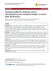
4.1 A Short Bridge: Bridge on the Aare River at Aarburg [2] This single span arch bridge crosses the Aare River at Aarburg. The completely clamped-in arch is a reinforced concrete structure from 1912 (Robert Maillart) whereas the bridge deck has been rebuilt in 1968 as a prestressed structure. The bridge deck is horizontally free at both abutments. This results Figure 8 Aare Bridge Aarburg. in the structure being simple (one span) and exhibiting simple and clearly defined boundary conditions. Therefore, the results of the single-input FVT investigation were of very good quality. Figures 9 and 10 show the comparison between an FE-analysis and the FVT-investigation results. The shaker shown in Figure 4 was located on the downstream (right-hand side in Figure 8) curb 10 m from the abutment. The forcing signal was of the random type with an upper band limit of fc = 36 Hz. The measurement point grid consisted of 105 and 41 3D-acceleration measurement points on the bridge deck and the arch respectively. One 3D-point was always located in the driving point (underneath the shaker). Another five 3D-points were roved over the structure. Figure 9 gives an idea of the resulting grid density. The sampling rate was s = 80 Hz, the length of a time window T = 51.2 s, the number of averages was 8, the total net testing time per cycle was 7 minutes, the total test took four nights between 10 pm and 5 am.
Figure 9 Frequency and shape of the first three bridge modes; FVT results to the right, updated FE model to the left. 4.2
Figure 10 MAC matrix (FVT versus FE model) for the first seven bridge modes. (scaling of the vertical axis: 0 to 1.).
A Long Bridge: Westend Bridge in Berlin [3]
This eight-span continuous beam bridge is part of the heavily trafficked Berlin city belt. The relatively short single columns are all clamped into a flat foundation. With the exception of one column in the middle of the bridge, which is also clamped into the bridge deck, the columns are pinned at their top end. There are several problems with this bridge from the point of view of a single-input FVT investigation. The bridge is too long and has too many spans. Especially bad is the short 31m-span in the middle of the bridge which cuts the structure into two dynamically almost "decoupled" parts (at least what vertical bending modes is concerned).
Figure 11 Westend Bridge Berlin. The view is opposite to the one used in Figure 12: Measurement points #1 to #5 are on the right-hand side of the photo shown here.
Figure 12 Measurement point grid for the Westend Bridge. #75 is the driving point (shaker position); the length of the individual spans is indicated in m.
The reason for this somehow strange span arrangement is the fact that the spans in the left-hand part of the photo (and in the right-hand part of the drawing shown in Fig. 12) are crossing several railway lines. The columns had to respect the position of the rail tracks. It was not possible to install a second shaker in this part of the bridge because access to the area underneath these spans was, a) not allowed and, b) not possible with vehicles. Due to the heavy traffic on the bridge, the time window for the tests was 10 pm to 4 am only. Outside of this window, nothing could be left on the bridge. There was hardly enough time to install/remove one shaker at position #75 (Fig. 12) with the infrastructure (hydraulic power pack, power generator) being located just underneath this point on the ground. The main results of the test are discussed in Figure 13. Here, the view is the same as used in Figure 12. Figure 13 Frequencies and shapes of the first five (out of nine [3]) modes of the Westend Bridge as derived from the FVT investigation and an updated FE-model. (MAC for the modes shown is in the MAC = 0.74…0.83 range.) It can be seen that: a) the frequency of f1 is too low to properly be excited, b) the second torsional mode f2 is not properly excited at the right-hand side of the bridge, c) the bending modes are well excited in the area of the shaker but not at the right-hand side of the bridge, d) the natural vibration dictated by the 31 m middle span is properly excited (f5).
4.3
A Dam: Norsjö Dam in Sweden [4]
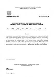
Norsjö Dam is a cylindrically shaped reinforced concrete structure with a length at the crest of 170 m and a maximum height of roughly 46 m (Fig. 14). The radius of curvature of the dam upstream face is r = 110 m. The dam width is 2.5 m at the crest and 5.5 m at the bottom (Fig. 15). The results of an FVT investigation of this dam using a servo-hydraulic shaker producing a horizontal force amplitude f = 32 kN for f < 1.5 Hz were of extraordinary good quality. Considering the results of a prelimiFigure 14 Norsjö Dam. nary FE analysis, the shaker was located some 60 m from the abutment at the first spillway wall (left-hand side on the photo). The forcing signal was of the random type with a band-limit at fc = 20 Hz. The tests could only be performed when the powerhouse was out of operation. The measurement point grid consisted of 270 3D-acceleration measurement points distributed over the dam crest and eight further levels between crest and foundation (it can be seen from Figure 15 that the whole downstream face of the dam is accessible), spillway walls and powerhouse. Four 3D-points were roved over the structure. The sampling rate was s = 100 Hz, the length of a time window T = 41 s, the number of averages was 8, the total testing time per cycle was about 6 minutes, the total test took two days (of a weekend) and four nights. Twelve modes with f = 3.0…13.5 Hz could be identified. Updating of an FE model was possible with very good results [4].
Figure 15 Norsjö Dam cross section.
Figure 16 Results for mode No. 5 (FEM and FVT shapes overlaid!).
5
Examples of AVT Investigations
5.1
A long Bridge: Ganter Bridge [5], [6]
This two-lane highway bridge with a total length of 678 m has eight spans with a length between 35 m and 174 m. The height of the tallest pylon is 176 m. Figure 18 shows the measurement point grid chosen for an AVT investigation. Including 192 points, this covered the bridge deck on its entire length plus the two tallest piers. At the bridge deck, the upstream sensors were of the 3D-, the downstream sensors of the vertical 1D-force balance type. As traffic remained open during the tests the accelerometers were placed inside the box girder. 3D sensors were fixed to the piers through professional climbers rappelling from the pier top (see Fig. 17). The two reference points chosen were equipped with a 3D and a 1D sensor respectively. Three 3D and three 1D sensors were roved in pairs along the structure. The big challenge of this test was to organize the cable management. The cable length available was 300 m per 3D and 1D sensor and the bridge deck was not Figure 17 The Ganter Bridge accessible for any piece of equipment (no curbs). It was therefore necessary to break down the test into four phases. Phase 1: The measurement center was located close to pier 2 on the ground (Station 1 in Fig. 18). Measurement of the bridge deck between the north abutment and the reference points. Phase 2: The measurement center was located between piers 4 and 5 (Station 2). Measurement of the bridge deck between the south abutment and the reference points. Phases 3 and 4: Measurement of piers 4 and 3 with the measurement center being located at stations 2 and 1 respectively.
Figure 18 Ganter Bridge: The measurement point grid.
Figure 19 The first eight modes.
The sampling rate chosen was s = 20 Hz, the length of a time window 53 minutes for the bridge deck and 27 minutes for the piers. The test took ten working days. A total of 25 modes could be identified in the frequency band f = 0.40…3.88 Hz. AVT proved to be a very good method to identify the dynamic parameters of such a large structure exhibiting very low natural frequencies.
Figure 20 Shapes of the Modes No. 1, 3 and 5 (elevation looking upstream and plan view). 5.2
A Short Bridge: Regensdorf Bridge Zurich [5]
The Regensdorf Bridge is a 30 m long and 14 m wide, skew steel-concrete composite structure. It consists of six riveted main girders and a concrete deck. The bridge undersight being inaccessible (railway lines), the challenge of the AVT investigation was to organize the measurements without disturbing the (heavy down-town Zurich) traffic too much. The existence of sidewalks is very helpful in such a case.
Figure 21 The measurement point grid.
Figure 21 shows the the measurement point grid. The two reference points are indicated with solid squares. Seven sensors were roved over the bridge deck. In a first phase, the curbs and the bridge centerline were measured without any interference to the traffic. Based on the intermediate (on-line) results it was decided to measure two additional lines. For this, the traffic flow was restricted to the remaining part of the bridge deck. The sampling rate was s = 80 Hz, the length of a time window 7 minutes. The test was accomplished in one day.
Figure 22 The first five bridge modes
The results are summarized in Figure 22. A total of 7 modes could be identified in the frequency band f = 4.80…18.55 Hz . Extraction of the mode shapes was based on vertically oriented measurements only, although some of the sensors were of the 3D-type. 5.3
A Bell Tower: St. Peter and Paul Church, Zurich
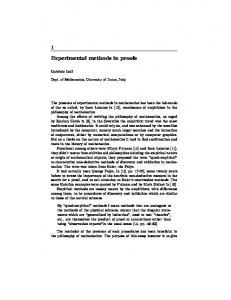
The tower of St. Peter and Paul Church is a 52 m high stone structure built in 1895. The measurement point grid used for an AVT investigation consisted of three horizontal degrees of freedom (accelerations) measured on the levels 2 to 6 as shown in Figure 23. Three sensors remained as reference points at level 6 while three further sensors were roved over the levels 2 to 5 in four setups.
Figure 23 Measurement point grid. Three sensors per measurement level.
Figure 24 The measurement center located at level 5.
To define the instrumentation necessary to determine the mode shapes of a structure like a tower or a tall building, several assumptions can be made: a) the vertical components can be neglected, b) the rectangular shape of the structure's cross section for a certain level above ground remains unchanged, and, c) the movements of the structure in the horizontal plane are small. It then suffices to measure three of the eight possible degrees of freedom of a rectangular cross section: x and y in one corner and y in a neighboring corner (Fig. 23). Advanced software packages allow to determine the remaining DOF's using so-called "slave node equations". The sampling rate was s = 25 Hz, the length of a time window 30 minutes. The test was accomplished in one afternoon. Nine modes with frequencies f = 2.30…8.9 Hz could be identified (Fig. 25).
Figure 25 St. Peter and Paul bell tower: Modal parameters for modes No. 1, 4, 5 and 8
6
References [1]
Cantieni, R. "Dynamic Load Tests on Highway Bridges in Switzerland - 60 Years Experience of EMPA". EMPA Report No. 211, (1983).
[2]
Cantieni, R., Deger, Y., Pietrzko, S., "Modal Analysis of an Arch Bridge: Experiment, Finite Element Analysis and Link". Proc. 12th International Modal Analysis Conference (IMAC), (1994) 425-432.
[3]
Deger, Y., Cantieni, R., Pietrzko, S.J., Rücker, W., Rohrmann, R., "Modal Analysis of a Highway Bridge: Experiment, Finite Element Analysis and Link". Proc. 13th International Modal Analysis Conference (IMAC), (1995) 1141-1149.
[4]
Cantieni, R. Assessing a Dam's Structural Properties Using Forced Vibration Testing, Proc. IABSE International Conference on Safety, Risk and Reliability - Trends in Engineering, Malta, March 21-23 (2001).
[5]
Felber, A.J. Cantieni, R., Introduction of a new Ambient Vibration System - Description of the System and Seven Bridge Tests, EMPA Report No. 156'521, (1996).
[6]
Felber, A.J., Cantieni, R., Advances in Ambient Vibration Testing: Ganter Bridge, Switzerland, Structural Engineering International (6), Number 3, (1996) 187-190.