Exploiting Temporal Coherence in Ray Casted Walkthroughs Vlastimil Havran∗ MPI Informatik
Jiˇr´ı Bittner† Vienna University of Technology
Abstract We present a technique that aims at exploiting temporal coherence of ray casted walkthroughs. Our goal is to reuse ray/object intersections computed in the last frame of the walkthrough for acceleration of ray casting in the current frame. In particular we aim at eliminating the ray traversal and computing only a single ray/object intersection per pixel. If our technique does not succeed in determining visibility, it falls back to the classical ray traversal. Visible point samples from the last frame are reprojected to the current frame. To identify whether these samples can be reused we apply splatting and epipolar geometry constraints. We discuss two additional techniques that handle correct appearance of small objects. We conducted a series of tests on walkthroughs of building interiors. Our method succeeded in determining visibility of more than 78% of pixels. For these pixels only a single ray/object intersection is executed. The frame rate is increased by up to 47%. Finally, we argue that the achieved speedup is relatively significant by comparing the performance of our algorithm to the “ideal” ray shooting algorithm. CR Categories: I.3.7 [COMPUTER GRAPHICS]: ThreeDimensional Graphics and Realism—Visible line/surface algorithms, Ray Tracing Keywords: hidden surface removal, temporal coherence, ray casting, ray shooting, reprojection, walkthroughs
1
Introduction
Ray casting was introduced by Appel [Appel 1968] to solve the problem of hidden surface removal already in the late 1960’s. Ray casting solves visibility by shooting rays through each pixel in the synthesized image and computing the closest ray/object intersection. This elementary visibility query is also called ray shooting [Arvo 1989]. Ray shooting has been thoroughly researched for more than three decades and it has been applied to solve various visibility problems [Durand 1999]. Currently the most common application of ray shooting are global illumination algorithms, such as ray tracing or path tracing [Arvo 1989]. The original application of ray shooting, the hidden surface removal, is nowadays typically resolved by the z-buffer algorithm [Catmull 1975] that is commonly implemented in graphics hardware. ∗ email:
[email protected] † email:
[email protected] ‡ email:
[email protected]
Hans-Peter Seidel‡ MPI Informatik
Z-buffer is a powerful algorithm for hidden surface removal, but it can be very inefficient for large scenes with a high depthcomplexity. In that case the algorithm needs to rasterize many scene objects even if they are invisible and the algorithm performs significant overdraw. The overdraw problem is commonly addressed by visibility culling methods [Hey and Purgathofer 2001] that aim to detect invisible parts of the scene and exclude them from rendering. The goal of these methods is to achieve output-sensitivity, i.e. a running time proportional to the number of visible objects. In contrast to the z-buffer algorithm, an efficient implementation of ray casting performs inherent visibility culling. Visibility at the pixel is resolved as soon as the closest ray/object intersection is found. Thus for large densely occluded scenes a software implementation of ray casting can outperform hardware accelerated zbuffered rendering even on the latest graphics hardware [Wald et al. 2001]. It has even been forecast that ray casting is likely to surpass z-buffer in the future for rendering highly complex scenes [Teller and Allex 1998; Wald et al. 2001]. Another advantage of ray casting over z-buffer is its versatility with respect to the type of primitives it handles. Ray casting can be applied easily for polygons, parametric surfaces such as NURBS, implicit surfaces, procedural objects, or CSG models. The common drawback of ray casting compared to most other hidden surface removal algorithms is that it does not exploit coherence of nearby rays. In this paper we exploit temporal coherence between rays shot in subsequent frames of walkthrough of a static scene. In our model we assume that the ray/object intersection and shading should be computed for each pixel and each viewing position. The goal of the proposed technique is to reduce the overhead of ray casting to computing a single ray/object intersection per pixel. We also discuss an extension of the method for ray tracing, namely the handling of the point light sources. We use a reprojection of visible points from the previous frame to the new frame to eliminate ray traversal. The reprojected points are used to determine the object that intersect the corresponding ray in the current frame. We identify problems that occur due to reprojection and propose techniques that handle them. If the reprojection does not succeed in determining visibility, we invoke the ordinary ray traversal algorithm.
2
Previous Work
Ray casting was introduced by Appel [Appel 1968] to address the hidden surface removal problem. Since then many techniques have been proposed to accelerate the elementary query that is often called ray shooting [Arvo 1989]. A naive implementation of ray shooting that tests all scene objects for an intersection with the given ray exhibits Θ(n) time complexity. Szirmay-Kalos [SzirmayKalos and M´arton 1998] has shown that the worst case lower bound of the ray shooting is Ω(logn). Havran [Havran 2001] shows experimentally that ray shooting based on kd-trees exhibits such a logarithmic behavior in average case. Ray shooting acceleration techniques typically use a spatial data structure to accelerate the ray traversal and to reduce the number of ray object intersections [Arvo 1989]. Temporal coherence between frames of an animation can be used to further improve the ray tracing performance. Sudarsky [Sudarsky 1993] surveyed ren-
dering techniques that exploit temporal coherence, more recent paper is by Demers et al. [Demers 1998]. Temporal coherence to accelerate rendering has been studied in the context of volume rendering [Gudmundsson and Randen 1990; Yagel and Shi 1993; Lin et al. 2000], visibility culling [Coorg and Teller 1996(b); Greene 1993; Bittner and Havran 2001], and global illumination [Walter 1999; Simmons 2000; Simmons and S´equin 2000; Martin et al. 2001; Reinhard et al. 2001]. The reprojection techniques are also commonly used in the context of point-based rendering [Pfister et al. 2000; Rusinkiewicz and Levoy 2000]. Our method is closely related to work of Badt [Badt 1988] who was the first to use reprojection for ray tracing acceleration. Our method is also similar to the reprojection technique of Adelson and Hodges [Adelson 1995] which approximates visibility and shading by reprojecting already shaded points and rechecking the visibility of primary rays explicitly. In contrast to the approaches mentioned above we aim at computing correct visibility and perform view-dependent shading. We eliminate artifacts introduced by the reprojection and introduce heuristics that handle the undersampling problem.
Figure 1: Dilatation of the object by 3 × 3 kernel. points from 3D space from the same object were reprojected to the pixel (ix, iy). If a point from another object has already been reprojected to pixel (ix, iy) and if its signed distance is bigger than t for the currently reprojected point, we overwrite the attributes at AIPi (ix, iy) by the attributes of the reprojected point. In the case of reprojecting a single object the splatting leads to a dilatation of the object illustrated in Fig. 1.
3.3
3
The New Algorithm
The proposed technique can be subdivided into the reprojection phase and the rendering phase. In the first frame we only invoke the rendering phase by using an ordinary ray shooting algorithm (ORSA). For computation of subsequent frames we first apply the reprojection phase followed by the rendering phase. We first discuss elementary data structures used in our algorithm followed by the discussion of the reprojection and the rendering phases.
3.1
Data Structures
For the further discussion we use a common perspective camera model. We assume that for the i-th frame of a walkthrough we generate an image on a viewing plane V Pi with respect to the center of projection Ci . The algorithm uses two auxiliary arrays of the same dimension as the image. All ray/object intersection points computed in the i-th frame are stored in an array denoted POSi (Points in Object Space). Each entry of POSi is a triple (P, O,t) addressable by pixel coordinates (x, y). P represents coordinates of a point in 3D space, O is a reference to the intersected object, and t is the signed distance along the ray to the object from center of projection Ci . Another 2D array AIPi (Auxiliary Image Plane) is used to maintain reprojected points for the i-th frame. Each entry of AIPi contains a triple (O,t, cnt). O is the reference to an object that is reprojected from the object space to the pixel, t is the smallest signed distance from the camera center to the object reprojected to the pixel, and cnt is the number of points reprojected to the pixel (x, y) of AIPi .
3.2
Reprojection
The reprojection constructs the AIPi array by reprojecting points of the POSi−1 array to the current viewing plane V Pi . For each entry of POSi−1 we reproject the corresponding 3D point by computing coordinates of corresponding pixel (x, y) in AIPi and the signed distance t from current camera position Ci . For each projected point we overestimate the influence of its projection by splatting using a 3 × 3 kernel: We examine the 3 × 3 neighborhood of a pixel (x, y). If no object has been reprojected to a pixel (ix, iy) (ix = x − 1, x, x + 1, iy = y − 1, y, y + 1), we store the attributes of the reprojected point to AIPi at (ix, iy). If the same object has already been reprojected to the AIPi at (ix, iy), we increment the counter AIP(ix, iy).cnt. In this way we count how many
Rendering
In the rendering phase we use the results of the reprojection to decide if it is sufficient to test the ray for intersection with a single object associated with the corresponding entry of AIPi , or if we have to apply the ORSA that considers all scene objects. For each pixel, the AIPi contains an information about the number of points from the closest object that are reprojected to the 3 × 3 neighborhood of the pixel. We compare this number with a constant (mcnt ) to decide if ORSA can be avoided. If the number of reprojected points is greater than mcnt , we compute an intersection of the given ray and the object associated with the corresponding entry of AIPi . Otherwise we invoke the ORSA. We found out experimentally that setting mcnt = 5 (as a majority from 9) the reprojection did not introduce any error at this step. The following two pseudocodes outline the reprojection and the rendering phases of the proposed method.
4
Reprojection Errors
Reprojecting points from 3D space onto the image plane does not guarantee the correctness of results for ray casting. There are two cases when the reprojection can fail: the view frustum error and the occlusion error. Similar sources of error in the context of image based rendering are called the external and internal exposure errors [McMillan 1997]. We discuss these two errors in the context of our ray casting algorithm and suggest methods to handle them.
4.1
View Frustum Error
The view frustum error is caused by appearance of an object that was previously outside of the current view frustum. Since there is no information about such an object in the POSi−1 array, it cannot be handled by the reprojection. This error can occur when the center of projection Ci is outside the view frustum of the previous frame. Fig. 2 shows an object Y that was not visible from C1, but becomes visible from C2 . The reprojection cannot handle the appearance of Y since the object was not intersected by any ray from C1 . To solve the view frustum error we check if the current camera position is outside the view frustum of the previous camera position. In such a case we skip the reprojection phase and compute visibility of all pixels by the ORSA. However, since in a walkthrough the camera is typically moving forward or rotates, the reprojection is almost always possible. Note that the view frustum error cannot occur for objects that appear in the view frustum due to camera
Algorithm 1 Reprojection Phase. Initialize all AIP items (O=0,t=∞,cnt=0). for each point P in POS do Reproject P to image plane, get coordinates of pixel (x, y) and signed distance t to P from current camera viewpoint. for each (ix, iy) in 3 × 3 neighborhood of pixel (x, y) do if (ix, iy) does not lie outside the image then if AIP(ix, iy).O 6= 0 then if AIP(ix, iy).t ≥ t then AIP(ix, iy).t = t if AIP(ix, iy).O ≡ P.O then Increment(AIP(ix, iy).cnt) else {Rewrite by closer object.} AIP(ix, iy).O = P.O AIP(ix, iy).cnt = 1 end if else if AIP(ix, iy).O ≡ P.O then Increment(AIP(ix, iy).cnt) end if end if else {First assignment to AIP(ix, iy)} AIP(ix, iy).O = P.O AIP(ix, iy).t = t AIP(ix, iy).cnt = 1 end if end if end for end for
Algorithm 2 Rendering Phase. Initialize POS. for each pixel (x, y) on the image plane do Initialize Ray(x, y) if AIP(x, y).cnt ≥ mcnt then if (Ray(x, y) intersects AIP(x, y).O) then {Intersection is found.} end if end if if Intersection has not been found by reprojection then Compute result for Ray(x, y) by ORSA. end if Compute color of pixel (x, y) for O and t. if Ray(x, y) hits an object O at the point P and the signed distance t then Add triple (P, O,t) to POS at (x, y) end if end for
Figure 2: View frustum error. Reprojection cannot handle appearance of an object that was outside of the view frustum.
rotation. Such objects are either behind entries in POSi−1 array (if also translation forward is involved) or there are no entries for the corresponding pixel and thus the ORSA is invoked.
4.2
Occlusion Error
The occlusion error is caused by appearance of previously occluded objects. If an occluded object becomes visible at a pixel (x, y), it is possible that the reprojection suggests that another object is visible at (x, y). This follows from the fact that we have no information about the previously occluded objects or their occluded parts. The occlusion error is illustrated in Fig. 3. For the camera position C1 object Y occludes object X between points c and d. For the camera position C2 the points on X between b and c reproject to the new viewing plane. Thus if there was a previously occluded object in the marked quadrilateral, it is missed by the reprojection phase. The reprojection cannot determine in advance whether there is an occluded object. We apply a method that identifies reprojected points that interfere with previously occluded regions in the reprojection (between b and c in our example).
Figure 3: Reprojection in general can result in incorrect results even if a new camera position lies in the view frustum of the previous camera position. The scene consists of two objects X and Y . If there was an object in the marked quadrilateral (in yellow color), it could be missed due to reprojection of points between b and c. The occlusion problem has been dealt in the context of image based rendering [McMillan 1997; Mark 1999], volumetric rendering [Gudmundsson and Randen 1990], and visibility preprocessing [Liu et al. 2000]. Our solution to the problem is an extension of the method of Gudmundsson [Gudmundsson and Randen 1990]. We apply a verification of a reprojected point with respect to the previously reprojected points that is based on their depths. If the verification fails, we discard the reprojected point.
The verification technique exploits properties of epipolar geometry of two camera positions. We project the current camera position Ci to the previous viewing plane V Pi−1 to obtain the epipole Ei−1. Similarly we project Ci−1 to V Pi to obtain the epipole Ei . The points are reprojected in an order of increasing distance from the epipole Ei−1 on V Pi−1 . We check if the points exhibit increasing distance from the epipole Ei on V Pi . If the distance on V Pi for the reprojected point is smaller, the point is a possible source of occlusion error and we discard it from the reprojection. To determine the correct reprojection order we subdivide the image plane V Pi−1 into four quadrants according to the epipole Ei−1. Within each quadrant we apply a different processing order of the points to guarantee that the reprojected point has a larger distance from the epipole Ei−1 than the previously projected points [Mark 1999][page 62]. The ordering is illustrated at the top of Figure 4.
update min/max for the row and the column and insert the reprojected point to AIPi . Otherwise the point is discarded since it can be a source of the occlusion error. The described processed is illustrated in Figure 4.
4.3
Undersampling Errors
The errors discussed above can occur due to missing information about invisible scene objects either due to view frustum restrictions or due to occlusion. In this section we discuss an additional source of error that can occur due to the discrete character of the method, namely the insufficient sampling density. Ray casting computes visibility of scene objects by sampling and so some small objects (below pixel size) can be missed. As the camera is moving the objects should become visible, but since we have no information about these objects they cannot be handled by the reprojection. As a solution to the problem we suggest to use regular resampling in the spatio-temporal domain. For each N-th frame we compute some pixels of the image using the ORSA. We use disjoint sets of pixels for each of the N subsequent images, which guarantees that after N frames all the pixels in N images were at least once computed “exactly” by the ORSA. We used N = 9, thus in each frame we compute one pixel in a window of 3 × 3 pixels using the ORSA (see Figure 5). The sampling pattern aims to minimize discrepancy in the spatio-temporal domain for straightforward camera motion. The pattern has been found experimentally by computing discrepancy of all possible patterns for 3 × 3 window.
Figure 5: Regular resampling pattern for a 3 × 3 window. In k-th frame, all pixels denoted by (k mod 9) + 1 are computed by the ORSA.
4.3.1
Figure 4: (Top) The order of point reprojection with respect to the V Pi−1. (Bottom) Result of the reprojection to V Pi . The order of reprojection and the min/max representation of the already projected points identifies possible occlusion problems. To check if the distance of a reprojected point from the epipole E2 is increased we keep maximal orthogonal distances of already reprojected points for each column and row of AIPi . For each reprojected point we compute its vertical distance to the row of the epipole and its horizontal distance to the column of the epipole. These distances are compared with the min/max distances (depending on the quadrant) stored at the column and the row the point projects to. If both distances are increased (in absolute values), we
Abrupt Camera Motion
The regular resampling is sufficient for smooth changes in camera position. For abrupt forward camera motion some small objects can still be undersampled and missed. We calculate for each new reprojected point if the forward movement of the camera was small enough to detect this object by regular resampling. Let an object Os at the signed distance t have footprint on the image plane of size S, thus at the signed distance t/2 the footprint of size 2S (the area of the footprint is four times larger). When S is below pixel size, it should be safely detected within N frames by regular reprojection, if we do not move the camera faster than δ = t/2/N distance at each frame. We assume that the object Os that we want to detect is attached to a larger already visible object. Thus we compute δ , taking t as a signed distance of each reprojected point. δ is compared with the size of the camera movement. If the camera movement is larger than δ , the point is approaching the camera “too fast” and it is discarded from the reprojection. Setting N = 9 in this context is theoretically correct but very conservative. In practice, setting N = 4 was sufficient and did not result in any visible artifacts in our test walkthroughs.
5
Implementation
In this section we briefly discuss the implementation issues and two optimization techniques.
5.1
Implementing Reprojection
The reprojection of a point is applied for each entry of the POS array. Therefore an efficient implementation of the reprojection is a key to achieve performance improvement of the proposed method. Unlike reprojection algorithms used in image-based rendering [McMillan 1997; Mark 1999], we need to compute a signed distance of the reprojected point from the camera center (required in Algorithm 1). Our implementation of reprojection based on the principle component of camera forward vector ~N precomputes 7 coefficients that are valid for the whole image. The reprojection of one 3D point requires the following operations: 8 × (+), 3 × (−), √ 12 × (∗), 1 × (/), 1 × ( ), and 2 × (IF). In our implementation the reprojection takes time comparable to computation of an intersection between a ray and a sphere. Thus it is reasonably fast not to become a bottleneck of the method.
5.2
Handling Background
The reprojection technique as described accelerates ray casting only for pixels at which some object is visible. We can extend our method to handle the empty pixels as follows: we represent the scene background by a bounding sphere of the scene centered at the center of the camera. The reprojection then handles the sphere in the same way as the other scene objects.
5.3
RayCasting
Results
As the ORSA we use a ray shooting algorithm using a kd-tree built according to the surface area heuristics with split-clipping [Havran 2001]. The reprojection algorithm was implemented in C++ and compiled using gcc-3.0.3 compiler. The tests were conducted on a PC equipped with AMD Athlon 1.1 GHz, 768 MB RAM, running Linux. We have tested our reprojection algorithm on walkthroughs of three different scenes: “townhouse”, “office”, and “theatre”. The “townhouse” scene contains 85k objects (see snapshot in Fig. 6left). The “office” scene contains 626k objects. The “theatre” scene contains 112k objects. The walkthroughs were rendered in resolution of 512 × 512 pixels. In order to quantify the success of the reprojection we compute the percentage of pixels computed by the single ray/object intersection (cR [%]) and by the ORSA due to failure of the reprojection (cE [%]). The number of pixels computed by the ORSA due to regular resampling was constant for all walkthroughs (cO = 11.1%). The results show the performance of the ORSA, two variants of our reprojection method (REPR1 and REPR2), and an ideal ray shooting algorithm IRSA. The ideal ray shooting algorithm[Havran
Method
TR
FR
ORSA REPR1 REPR2 IRSA
701.1 478.4 478.3 344.3
1.17 1.72 1.72 4.05
Parameters N˜ IT N˜ T S 9.23 3.37 3.35 0.98
52.0 12.2 11.8 0.0
cE [%]
cR [%]
– 10.9 10.5 –
– 78.0 78.4 –
Table 1: Results for the “townhouse” scene (85k objects). The walkthrough consists of 825 frames. TR is the total time of rendering (including Phong shading), FR is the average frame rate. ORSA is the ordinary ray shooting algorithm based on a kd-tree for each pixel. REPR1 is the reprojection algorithm as described in Section 3. REPR2 is REPR1 combined with ”shifting ray origin”. IRSA is an ideal ray shooting algorithm; note that N˜ NIT < 1 since a background is visible.
Shifting Ray Origin
Even if the reprojection fails due to insufficient number of reprojected points (Section 3.3) we know that the ray/object intersection cannot occur within certain signed distance from the viewpoint. We can thus start the ORSA with a shifted ray origin. By shifting a ray origin forward along the ray we avoid the traversal of empty nodes of a spatial data structure used for computing the ray traversal. The ray origin is shifted from the center of projection Ci by t − ε , where t is the computed signed distance and ε is a small positive constant required for numerical robustness of the algorithm.
6
2001] is an abstract concept that uses the results of the ORSA to determine the performance of computing ray/object intersections if the intersected object is already known. The results are summarized in Table 1, 2, and 3. The proposed method achieves the following increase of the average frame rates: 1.17 to 1.72 for the “townhouse” scene, 1.66 to 1.89 for the “office” scene, 1.19 to 1.39 for the “theatre” scene. We note that the ORSA used in our test is an already highly optimized algorithm that is considered one of the most efficient ray shooting techniques [Wald et al. 2001]. The reprojection algorithm would provide a more significant speedup for less efficient ray shooting algorithms.
Method
TR
FR
N˜ IT
N˜ T S
cE [%]
cR [%]
ORSA REPR1 REPR2 IRSA
979.6 837.9 835.9 373.8
1.19 1.39 1.39 3.11
3.79 2.73 2.69 0.999
58.1 26.0 24.6 0.0
– 31.1 31.1 –
– 57.8 57.8 –
Table 2: Results for the “theatre” scene (112k objects). The walkthrough consists of 1165 frames. Method
TR
FR
N˜ IT
N˜ T S
cE [%]
cR [%]
ORSA REPR1 REPR2 IRSA
892.3 789.4 801.5 354.6
1.66 1.89 1.85 4.19
3.02 1.89 1.88 0.71
44.5 21.9 21.7 0.0
– 33.6 33.6 –
– 55.3 55.3 –
Table 3: Results for the “office” scene (626k objects). The walkthrough consists of 1489 frames.
7 7.1
Discussion Visual Quality
Firstly, we verified the visual quality of the generated images. As a reference we used images generated by the ORSA on the same walkthrough sequence. We did not observe any visual artifacts caused by the reprojection for all tested walkthroughs.
7.2
Speedup
We increased the frame rates from 14% to 47% and achieved the performance 1.70 to 2.23 times slower than the ideal ray shooting algorithm IRSA. These numbers include time of shading at the computed ray/object intersection points. If we exclude time for
shading and evaluate speedups for pure visibility computation, we achieve frame rate increases for computing visibility between 18% and 82%. This evaluation is based on code profiling; the profiler reported that about 30% of the total rendering time of the ORSA was spent in the shading routine. The speedup obtained by the reprojection is proportional to the number of pixels the reprojection succeeds on. The utilization of reprojection increases with the resolution of generated images and decreases with the number of visible silhouettes and their length. The length of the silhouettes in the image increases linearly with resolution, but the number of pixels rendered increases quadratically. This suggests that the presented method has a greater potential for a high resolution rendering. Surprisingly we have observed that the acceleration technique that shifts the ray origin (REPR2) did not perform as well as expected. It provided a slight speedup for the “theatre” scene, but for the “office” scene it led to a slight performance loss. We conclude that this is caused by its computational overhead that is simply too high to further improve the already quite efficient ray casting implementation. The technique for handling the background is computationally inexpensive, but since the tested scenes did not contain many empty pixels its impact could not be properly evaluated.
7.3
Limits of Ray Casting Acceleration
We discuss the limits of ray casting acceleration and relate the speedup provided by our technique to these limits. Our discussion is based on the abstract concept of the ideal ray shooting algorithm (IRSA) that knows exactly which object is intersected by the given ray. In other words such an algorithm acts as an ideal predictor for each input ray. The experimental measurements (Tables 1, 2, and 3) show that even the ORSA based on kd-trees is relatively close to the optimal algorithm: it is 1.93 to 2.75 times slower than IRSA for the tested scenes. Also the hardware-independent values such as number of ray/object intersections and the number of traversal steps are very close to ideal state. Thus the space for an improvement is already quite small. The main reason why the performance increase of our method is relatively small (14% to 47%) is the proximity of the achieved running time to the IRSA. Judging from these results we conjecture that further algorithmic acceleration of ray shooting is very complicated. We see a greater potential for acceleration by reducing the number of rays cast [Scheel et al. 2001] (thus obtaining “less precise” images) or by exploiting explicitly parallel computations [Wald et al. 2001].
7.4
Extension for Shadow Rays
We discussed several source of errors due to the reprojection and proposed methods that handle these errors. In particular we used splatting, checking camera position with respect to the view frustum, ordered reprojection, regular resampling, and handling abrupt camera motion. We suggested two optimization techniques to handle the image background and to accelerate ray traversal by shifting the ray origin. We verified our algorithm by a series of tests. On the tested walkthrough sequences the reprojection succeeded in determining of up to 78% pixels. The frame rate was increased approximately by 14 to 47% for moderately sized scenes. We discussed the achieved results in the context of the limits of ray shooting acceleration. We have shown that the proposed technique is relatively close to the “ideal” ray shooting algorithm. In particular it is 1.70 to 2.23 times slower than the ideal state. This observation suggests that a further purely algorithmic acceleration of ray casting with conservative results is very complicated. We see a greater potential for acceleration by reducing the number of rays cast or by explicit parallelization. In the future we plan to investigate properties of our algorithm in context of global illumination methods. We would also like to extend the algorithm for scenes with moving objects.
Acknowledgements Here, we want to thank Philippe Bekaert for providing us the scene models for research purposes and Jaroslav Kˇriv´anek for having comments on previous version of the paper. Further, we would like to thank all anonymous reviewers of the previous version of the paper. This work has been partially supported by the Austrian Science Foundation (FWF) contract no. p-13876-INF and by IST 200134744 funding.
References A DELSON , S.J., H ODGES , L.F. 1995. Generating Exact Ray-Traced Animation Frames by Reprojection. In Journal IEEE-CG&A, 15, 3, 43–52. A PPEL , A. 1968. Some Techniques for Shading Machine Renderings of Solids. In AFIPS 1968 Spring Joint Computer Conf., vol. 32, 37–45. A RVO , J., K IRK , D. 1989. A Survey of Ray Tracing Acceleration Techniques. Academic Press, 201–262. B ADT, J.S. 1988. Two Algorithms for Taking Advantage of Temporal Coherence in Ray Tracing. The Visual Computer, 4, 3, 123–132. B ITTNER , J., H AVRAN , V. 2001. Exploiting Temporal and Spatial Coherence in Hierarchical Visibility Algorithms. In Journal of Visualization & Computer Animation, 12, 5, 277–286.
In the scope of ray tracing it is significantly more difficult to exploit temporal coherence of secondary rays than the coherence of primary rays [Adelson 1995]. For a moving camera the secondary rays have low coherence with respect to directions and origins of the rays in the previous frame. However, the reprojection can be extended to handle direct illumination by point-light sources similarly to method of Adelson [Adelson 1995]. This technique can also be extended to handle area light sources approximately.
C ATMULL , E.E. 1975. Computer Display of Curved Surfaces. In Proceedings of the IEEE Conference on Computer Graphics, Pattern Recognition, and Data Structures, 11–17.
8
D EMERS , J., Y OON , I., K IM , T.-Y., N EUMANN , U. 1998. Accelerating Ray Tracing by Exploiting Frame-To-Frame Coherence. Technical Report 1998/668, Computer Science Department, The University of Southern California, Los Angeles.
Conclusion and Future Work
We presented a novel method for ray casting acceleration that exploits temporal coherence in the scope of walkthroughs of static scenes. The proposed method uses reprojection of the set of visible points from the previous frame to guide ray casting in the current frame. The aim of our technique was to eliminate the ray traversal and to compute only a single ray/object intersection per pixel.
C OORG , S., T ELLER , S. 1996. Temporally Coherent Conservative Visibility. In Proceedings of the Twelfth Annual Symposium On Computational Geometry (ISG ’96), ACM Press, 78–87. C OORG , S., T ELLER , S. 1996. A Spatially and Temporally Coherent Object Space Visibility Algorithm. Technical Report TM-546, Department of Computer Graphics, MIT.
D URAND , F. 1999. 3D Visibility: Analytical Study and Applications. PhD thesis, Universite Joseph Fourier, Grenoble, France. G REENE , N., K ASS , M. 1993. Hierarchical Z-buffer Visibility. In Proceedings of ACM SIGGRAPH’93, ACM Press / ACM SIGGRAPH, 231–240.
(a)
(b)
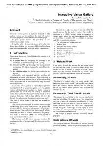
Figure 6: (a) A snapshot from a walkthrough of the “townhouse” scene. (b) Visualization of the reprojection and the rendering phases. Red pixels are computed successfully by a single ray/object intersection, green pixels have been computed exactly by the ORSA due to reprojection failure, white pixels are computed by the ORSA due to regular resampling, and blue pixels are computed by the ORSA due to detection of abrupt camera motion. The profiler reported 14.7% of time spent by reprojection phase, 41.4% spent by computing the normal and Phong shading, 2% spent by the initialization of rays, 25.5% spent by the ORSA, 3.24% spent by computing single ray/object intersection, and the rest (13.2%) spent in the main ray casting function. G UDMUNDSSON , B., R ANDEN , M. 1990. Incremental Generation of Projections of CT-Volumes. In In Proceedings in The First Conference on Visualization in Biomedical Computing, Atlanta.
¨ , J., S EIDEL , H.-P. 2001. EnhanceS CHEEL , A., S TAMMINGER , M., P UTZ ments to Directional Coherence Maps. In Proceedings of WSCG’01, 403–410.
H AVRAN , V. 2001. Heuristic Ray Shooting Algorithms. PhD thesis, Czech Technical University in Prague, Czech Republic.
S IMMONS , M. 2000. A Dynamic Mesh Display Representation for the Holodeck Ray Cache System. Technical Report CSD-00-1090, University of California, Berkeley.
H EY, H., P URGATHOFER , W. 2001. Occlusion Culling Methods. In State of the Art Report, in Proceedings of Eurographics 2001. L IN , Q. D ANIELSON , P.-E., G UDMUNSON , B. 2000. Frame-Coherent Volume Rendering. In Proceedings of the IASTED International Conferent, COMPUTER GRAPHICS AND IMAGING. L IU , X., S UN , H., W U , E. 2000. Visibility Preprocessing with Occluder Fusion for Urban Walkthroughs. Proceedings of VRST2000, 55–60. M ARTIN , W., PARKER , S., S HIRLEY, P., T HOMPSON , W. 2001. Temporally Coherent Interactive Ray Tracing. Technical Report UUCS-01-005, Computer Science Department, University of Utah. M ARK , W.R. 1999. Post-Rendering 3D Image Warping: Visibility, Reconstruction, and Performance for Depth-Image Warping. PhD thesis, Chapel Hill, University of North Carolina. M C M ILLAN , L. 1997. An Image-Based Approach to Three-Dimensional Computer Graphics. PhD thesis, Chapel Hill, University of North Carolina. P FISTER , H., Z WICKER , M., VAN B AAR , J., G ROSS , M. 2000. Surfels: Surface Elements as Rendering Primitives. In Proceedings of ACM SIGGRAPH 2000, ACM Press / ACM SIGGRAPH, 335–342. R EINHARD , E., S HIRLEY, P., H ANSEN , C. 2001. Parallel Point Reprojection. In Proceedings of the 2001 IEEE Symposium on Parallel and Large-Data Visualization and Graphics. R USINKIEWICZ , S., L EVOY, M. 2000. QSplat: A Multiresolution Point Rendering System for Large Meshes. In Proceedings of ACM SIGGRAPH 2000, ACM Press / ACM SIGGRAPH, 343–352.
S IMMONS , M., S E´ QUIN , C.H. 2000. Tapestry: A Dynamic Mesh-based Display Representation for Interactive Rendering. In Rendering Techniques 2000, 329–340. S UDARSKY, O. 1993. Exploiting Temporal Coherence in Animation Rendering. Technical Report CIS9326, Technion - Computer Science Department, Israel. ´ S ZIRMAY-K ALOS , L., M ARTON , G. 1998. Worst-Case Versus Average Case Complexity of Ray-Sshooting. In Journal Computing, 61, 2, 103– 131. T ELLER , S., A LLEX , J. 1998. Frustum Casting for Progressive, Interactive Rendering. Technical Report MIT LCS TR-740, MIT. WALD , I., S LUSALLEK , P., B ENTHIN , C., WAGNER , M. 2001. Interactive Rendering with Coherent Ray Tracing. EG 2001 Proceedings, in journal Computer Graphics Forum, 20, 3, 153–164. WALTER , B., D RETTAKIS , G., PARKER , S. 1999. Interactive Rendering Using Render Cache. In Rendering Techniques ’99, 19–30. YAGEL , R., S HI , Z. 1993. Accelerating Volume Animation by SpaceLeaping. In Proceedings of Visualization’93, 62–69.