Exploring a Low-Cost and Power-Efficient Hybridization Technique for 3D NoC-Bus Hybrid Architecture using LastZBased Routing Algorithms Amir-Mohammad Rahmani1,2*, Pasi Liljeberg1, Juha Plosila1, and Hannu Tenhunen1 1
Embedded Computer and Electronic Systems Laboratory, Department of Information Technology, University of Turku, Turku, Finland {amir.rahmani, pasi.liljeberg, juha.plosila, hannu.tenhunen}@utu.fi 2
Turku Centre for Computer Science (TUCS), Turku, Finland
* corresponding author: Amir-Mohammad Rahmani Address: University of Turku Department of Information Technology Joukahaisenkatu 3-5 B, 5th floor 20520 Turku, Finland Office : (+358) 23338669 Fax
: (+358) 23336950
Email
:
[email protected]
Date of Receiving: to be completed by the Editor Date of Acceptance: to be completed by the Editor
Exploring a Low-Cost and Power-Efficient Hybridization Technique for 3D NoC-Bus Hybrid Architecture using LastZBased Routing Algorithms Amir-Mohammad Rahmani, Pasi Liljeberg, Juha Plosila, and Hannu Tenhunen Abstract — Three-dimensional (3D) integration in which multiple active silicon layers are stacked above each other and vertically interconnected offers shorter interconnection wire for Networks-onChip (NoC). The simple 3D NoC architectures such as Symmetric 3D Mesh NoC could not exploit the beneficial feature of a negligible inter-layer distance in 3D chips. In order to exploit the intrinsic capability of reducing the wire length in 3D ICs, 3D NoC-Bus Hybrid architecture was proposed. This architecture suffers from naive and straightforward hybridization between NoC and bus media. In this paper, an efficient hybridization scheme is presented to enhance system performance, power consumption, and area of 3D NoC-Bus Hybrid architectures. The hybridization mechanism benefiting from a rule called LastZ enables low-cost inter-layer communication architecture. In the proposed architecture, instead of using the conventional 6×6 routers, 5×6 routers were utilized which offers many advantages. To estimate the efficiency of the proposed architecture, the system has been simulated using synthetic (uniform, hotspot 10%, and Negative Exponential Distribution) traffic patterns as well as real benchmarks, including the one with an integrated videoconference application. Compared to a conventional 3D NoC-Bus Hybrid Mesh architecture, our extensive simulations reveal significant area, power, and performance improvements for the proposed LastZbased hybridization scheme. Keywords — Networks-on-Chip; 3D ICs; 3D NoC-Bus Hybrid Architecture; Routing Algorithm; Low-Power Design;
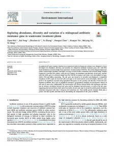
1 INTRODUCTION As technology scales down in today’s many-core chip multiprocessors (CMPs), providing efficient communication in a single die has become one of the critical factors for modern system designs. To get full benefits of parallel processing containing tens to hundreds of processors, a multiprocessor system needs efficient on-chip communication architecture [1]. The Networks-on-Chip (NoCs) paradigm, based on a modular packet-switched mechanism, was proposed as a promising communication platform because of scalability, better throughput and reduced power consumption [2]. However, increasing the number of cores over a 2D plane is not efficient due to long interconnects and distance [3]. Three-dimensional (3D) integration is a viable design paradigm to overcome the existing interconnect bottleneck in integrated systems and enhance system power/performance characteristics. In 3D integration technology, multiple layers of active devices are stacked above each other and vertically interconnected using Through-Silicon Vias (TSVs). The major advantage of this emerging technology compared to 2D designs is the inherent reduction in wire length [4][5]. As a result, 3D integration enhances communication performance and reduces power consumption, compared with 2D NoCs [6]. The 3D Symmetric NoC architecture can be simply created by adding two additional physical ports to each router for interlayer communication [7]. Despite simplicity, this architecture has two major inherent drawbacks. Firstly, it does not exploit the beneficial feature of a negligible inter-wafer distance in 3D chips, because in this architecture, inter-layer and intra-layer hops are indistinguishable. Secondly, a considerably larger crossbar is required as a result of two extra ports [3]. The stacked mesh 3D NoC (Hybrid NoC-Bus 3D mesh) architecture presented in [8] is a hybrid architecture between the packet switched network and the bus architecture to overcome the mentioned 3D Symmetric NoC challenges. It takes advantage of the short inter-layer distances that are characteristics
of 3D ICs [3][9]. It integrates the multiple layers of 2D mesh networks by connecting them with a bus spanning the entire vertical distance of the chip as shown in Fig. 1. By using the stacked mesh architecture, six-port router is required instead of seven ports for typical 3D NoC router. However, the additional input port still imposes considerable extra logic to a NoC router, especially when complex routers with support of Virtual Channels (VCs) and load management schemes are required. In this paper, we propose a novel hybridization scheme for inter-layer communication using an efficient 5-input router to enhance the overall system power, performance, and area characteristics of the existing Hybrid NoC-Bus mesh architecture. By defining a rule for routing algorithms called LastZ, the proposed area-efficient architecture decreases the overall average hop count of a NoC-based system compared to the existing architectures. In addition, an extremely low-cost wrapper is presented to provide the compatibility of the proposed vertical communication scheme with existing network interfaces. The remainder of the paper is organized as follows. Section 2 covers the previous researches and developments in related area and introduction to existing 3D NoC architectures. Section 3 elaborates the demands for LastZ routing policy. Section 4 presents the proposed architecture including hybridization scheme, router architecture, and wrapper design. Our experimental results are discussed in Section 5 while Section 6 highlights the pros and cons of the proposed communication scheme. Finally, Section 7 concludes this paper.
2 RELATED WORK The 3D NoCs are extension to the 2D NoC architecture. For each NoC router of mesh topology, two extra ports are needed resulting a 7×7 crossbar instead of the 5×5 crossbar of the 2D mesh architecture. Since, the crossbar power increases quadratically with number of ports, the power consumption of a 3D router is much higher than a 2D router [9]. The solution to the power
consumption and inefficient utilization of vertical links for a 3D router has been proposed by Li et al. [8]. The proposed architecture is Hybrid NoC-Bus mesh architecture. The dynamic Time-Division Multiple Access (dTDMA) bus was used as a communication pillar as shown in Fig. 2. In this architecture, an interface between the dTDMA pillar (vertical link) and the NoC router must be provided to enable seamless integration of the vertical links with the 2D network within the layers. An extra physical channel is added to the router for the vertical communication. This channel has its own dedicated buffers, and is indistinguishable from the other channels. Bus arbiters should be placed in the middle layer to keep wire lengths as uniform as possible. Due to one hop vertical communication and 6×6 routers, proposed architecture offers better characteristics in terms of power consumption and latency. The issue with this architecture is that it still has a large crossbar and low throughput due to inefficient hybridization of NoC and Bus media. We propose a new hybridization technique to further enhance the throughput, area, and power by utilizing a low-cost router architecture and an efficient bus connectivity using LastZ-based routing algorithms. Kim et al. [3] offered an efficient router structure for 3D NoCs called True NoC architecture. In the architecture, the vertical links are embedded in the crossbar and extend to all layers. Interconnection between the various links in a 3D crossbar would have to be provided by dedicated connection boxes at each layer. The improved architecture of the True 3D NoC router called DimDe has been proposed which reveals the rather enhanced energy-delay product characteristic. Despite their encouraging results, there are some important drawbacks. Adding a large number of vertical links in a 3D crossbar to increase NoC connectivity leads to increased path diversity and means multiple possible paths between source and destination pairs. It actually leads to a dramatic increase in the complexity and power consumption of the central arbiter. In addition, their design can only support dimension-ordered routing (DOR), which is known to suffer from poor worst-case throughput.
Based on the idea of vertical switching, Matsutani et al. [10] proposed an architecture called XNoTs. The architecture is not power-efficient, because it requires large vertical switches. Park et al. [11] proposed MIRA, which is based on implementing a 2D mesh chip-multiprocessor in three dimensions. The major drawback of the architecture is that it assumes the processor cores are designed in 3D. This makes it difficult to reuse existing highly optimized 2D processor core designs. Most of the discussed architectures are either power efficient or high performance. Symmetrical 3D NoC architecture is high-throughput but not power efficient. On the other hand, architectures like True NoC or Hybrid NoC-Bus mesh architecture are power efficient at the expense of reduced throughput. We re-hybridize the Hybrid NoC-Bus mesh architecture not only without adding extra communication resources but also by simplifying the router architecture and enhance network performance, power efficiency, and system cost.
3 LASTZ ROUTING POLICY As discussed in Section 2, a 6×6 router has many disadvantages over its 5×5 counterpart. For instance, based on the reported results in [3] for 90nm CMOS technology, a 6-port router incurs around 36% area and 20% power overheads compared to a 5-port one. On the other hand, the packet delay to cross the router increases because more input channels compete to get access to the target output port. The larger crossbar also increases the router critical path and thereby reduces the router maximum operating frequency. Our investigation shows that a straightforward hybridization of two different communication media (i.e. NoC and Bus) without considering their intrinsical characteristics is not an efficient strategy. Fig. 3 shows the conventional hybridization style of a Hybrid NoC-Bus mesh-based system. In this architecture, stacked routers in different layers are connected to a vertical bus. The routers are able to serve as either a master or a slave depending on the arbitration decision. The bus protocol is based on
the work presented in [8]. The dTDMA policy is used for arbitration and the bus arbiters are placed in the middle layer to keep wire distances as uniform as possible. TSVs are used to implement interlayer control signals. The number of control signals grows with the number of layer. Surprisingly, as will be shown later, just by following one basic rule in routing algorithm policy, it is possible to remove one input port and substitute 6×6 routers with 5×6 ones. 3.1
LastZ rule
In 3D NoC, the packet routing process is classified into two different categories: intra-layer routing and inter-layer routing. For the 3D Hybrid NoC-Bus mesh architecture, the intra-layer packet routing is multi-hop because traditional NoC architecture is utilized for communication. In multi-hop communication, packet routing plays a crucial role because there are many minimal or non-minimal paths to send a packet from a source to a destination. In contrast, for inter-layer communication, the 3D Hybrid NoC-Bus mesh architecture benefits from bus-based one-hop communication. In this work, we define a rule which we call LastZ. Definition 1 (LastZ): In the wormhole packet switching approach messages are sent by means of packets composed of flits (flow control unit) [12]. A 3D routing algorithm is LastZ-based if the intralayer routing process is completed before the inter-layer routing. In other words, in a LastZ-based routing algorithm, when a node Nsource sends a flit to a node Ndestination, the flit will first travel along the X or Y direction (statically or adaptively) in Nsource dimension until the flit reaches the pillar (vertical inter-layer
bus)
having
the
same
x-
and
y-
coordinates
as
the
destination
node
(Flitxy=Destination_Pillarxy). If a TSV sharing technique [13] is used to provide one bus for a group of destination nodes, the condition can be revised as Flitxy =Destination _Pillar_Groupxy. Then the flit will traverse the last hop in the Z direction. As will be shown later, this rule is astonishingly beneficial to improve system characteristics. It is
noteworthy that this rule does not force significant limitations to a routing algorithm owing to the onehop bus-based vertical communication. Many of recently proposed architectures benefit from routing algorithms being by default LastZ-based such as [14][15][16][17][18].
4 PROPOSED HYBRIDIZATION ARCHITECTURE Based on the defined LastZ rule, assume that a packet, after complete intra-layer routing, has reached the destination pillar (vertical bus). In this case, it is obvious that one of the connected routers to the vertical bus is the last router (hop) for delivering the packet to the target processing element (PE). Based on the fact that the destination is already known, it is not wise to send the packet again to the respective router for the routing decision making. Instead, it is more efficient to deliver the packet to the connected PE directly. The explained scenario was the motivation to propose a new hybridization scheme for connecting components to a vertical bus. The proposed architecture is shown in Fig. 4. As can be seen in the figure, it is practical to establish a more efficient inter-layer communication scheme without adding any extra workload and hardware to bus arbiters. Based on the proposed hybridization architecture, routers just serve as masters to initiate the transaction and PEs play the slave role and via the intermediate buffers directly receive their own packets. In the proposed communication scheme, routers do not need any input port for the Up/Down direction, because they are bypassed by intermediate buffers. Fig. 5 shows the high level view of the proposed Hybrid NoC-Bus mesh architecture. As can be seen in the figure, the intermediate input buffer which was used as an interface between a router and a dTDMA bus, in this architecture connects a PE directly to the vertical bus. Bypassing routers enables a 3D NoC to utilize a 5×6 router instead of a larger 6-input port router. As will be demonstrated later, this also offers many astonishing advantages. It should be mentioned that in the proposed architecture, PEs deliver packet from two
different sources: PEs in the same layer or from other layers. If it is desirable to use the existing network interfaces (NI), it will necessitate benefiting from a small wrapper. Later, we will present the implementation of a 2×1 wrapper, however a dual-input-port NI can more efficiently exploit the offered bandwidth. This type of NI has been presented for the number of NoC architectures such as NePA [19] and DMesh [20]. Fig. 6 illustrates the main components of a generic 5×6 router for the proposed 3D Mesh-based architecture. In this case, a router has 5 input ports (four for cardinal directions and one for a local PE) and 6 output ports (one additional channel for vertical communication), supporting V virtualchannels (VCs) per port. Virtual-channel flow control exploits an array of buffers at each input port to improve both throughput and latency by allowing blocked packets to be bypassed. When a flit is ready to be sent, the switch connects an input buffer to an appropriate output channel. The router also comprises of three main modules to control the datapath: a router, a virtual-channel (VC) allocator, and a switch allocator. These components decide the direction of next hop, the next virtual channel, and when a switch is available for each flit. 4.1
Wrapper architecture
In order to utilize the existing single-input-port NIs and also to benefit from the proposed architecture, a simple 2×1 wrapper is required. In such cases that there are two concurrent requests for sending packets to a NI buffer, this wrapper performs the arbitration process. More precisely, the wrapper comprises of a simple finite state machine (FSM) and multiplexers to connect the respective input channel to the output channel based on an arbitration policy such as round-robin, priority-based, etc. The state machine in our wrapper is quite simple and area efficient. To be fair, we choose the roundrobin policy for arbitration. It should be noted that to maintain full compatibility with the existing NI transmission protocols, a packet-based arbitration is used. This means that the arbitration is performed
for each packet, not for each flit. The state machine contains four main states, which are XY-Turn, XYSending, Z-Turn and Z-Sending as shown in Fig. 7. At the initialization time of the whole system, access to the output port is granted to the intra-layer communication (XY-Turn). In this state, if there is a request from an intra-layer router (Req_XY = ‘1’), it will be granted and the current state will be changed to XY-Sending. The current state remains in XY-Sending as long as the packet is being sent. End-of-packet signal (eop_XY = ‘1’) indicates the transmission completion for intra-layer communication. At this time, the current state switches to Z-Turn indicating this is the inter-layer buffer turn to send a packet (Req_XY = ‘0’ and Req_Z = ‘0’). Alternatively, it will directly get the ZSending state, on condition that there is a request from the inter-layer buffer (Req_Z = ‘1’). At the initial stage (XY-Turn), providing that there is no request from the router (Req_XY = ‘0’), the request signal from the inter-layer buffer will be checked. If there is a request from the buffer (Req_Z = ‘1’), the current state will switch to Z-Sending and the packet transmission will be initiated. A similar procedure is followed when the current state is Z-Turn. Our experiments reveal that typically the competition on the wrapper side is not too high even when a network is fully loaded. Based on the fact that bus is not a concurrent medium, it is not common for an intermediate buffer to receive grants from a bus arbiter unceasingly. This fact indicates that the presented wrapper has a negligible impact on network average packet latency.
5 EXPERIMENTAL RESULTS To demonstrate the better performance, power, and area characteristics of the proposed 3D NoC, an in-house cycle-accurate NoC simulation environment was implemented in VHDL. Hybrid Bus-NoC 3D-mesh [21], and the proposed architecture using LastZ-based routing algorithms were analyzed for different traffic patterns. For the typical NoC, the on-chip network considered for experiment is formed by a typical state-of-the-art router structure including buffers, a routing unit, a switch allocator,
VC allocators (for the second and third experiment sets) and a crossbar. For the Hybrid NoC-Bus based System, routers have 6 input/output ports and for the proposed architecture, routers have 5 input and 6 output ports. All routers were designed in RTL and are fully synthesizable. The arbitration schemes for the switch allocator and the wrappers are based on round-robin. 5.1
Synthetic Traffic Analysis
To perform the simulations under synthetic traffic profiles, we used uniform, hotspot 10%, and Negative Exponential Distribution (NED) [22] traffic patterns. In the uniform traffic pattern, a node sends a packet to other nodes with an equal probability while in the hotspot traffic pattern, messages are destined to a specific node with a certain (10% higher than average) probability and are otherwise uniformly distributed. The NED is a synthetic traffic model based on Negative Exponential Distribution where the likelihood that a node sends a packet to another node exponentially decreases with the hop distance between the two cores. This synthetic traffic profile accurately captures key statistical behavior of realistic traces of communication among the nodes. The performance of the network was evaluated using latency curves as a function of the packet injection rate. The packet latency was defined as the time duration from when the first flit is created at the source node to when the last flit is delivered to the destination node. For each simulation, the packet latencies were averaged over 50,000 packets. Latencies were not collected for the first 5,000 cycles to allow the network to stabilize. It was assumed the buffer size of each FIFO was eight flits, and the data width was set to 64 bits. In the first experiment set, 3×3×3 3D meshes and packets with a length of nine-flits were used. For average packet latency analysis, the static XYZ [23] wormhole routing algorithm was used. Owing to the deadlock-free nature of this routing algorithm, we used routers without virtual channel for this experiment set. The packet latencies for different traffic profiles are shown in Fig. 8. For the hotspot 10% traffic pattern, the node at (2, 2, 2) is destined as the hotspot node. It can be observed for all the
traffic patterns, the network with the proposed architecture saturates at higher injection rates and always offers reduced average packet latency compared to the typical Hybrid Bus-NoC 3D mesh. The more important reasons for this performance improvement are the reduced total average hop count, the high-speed router, and the high-throughput network as discussed in Section 4.1. In the second experiment set, we changed some of the NoC parameters considered in the first set of experiments. For the simulations, 3×3×4 (4 layers) 3D meshes and packets with a length of twelve-flits were used. To assess the average packet latency, (DyXY)Z [24] wormhole routing algorithm was utilized. More precisely, firstly packets follow the adaptive DyXY routing algorithm to reach target buses, and then via the inter-layer bus they are delivered to target PEs. In DyXY algorithm, which is based on the static XY algorithm, a packet is sent either to the X or Y direction depending on the congestion condition. It uses local information which is the current queue length of the corresponding input port in the neighboring routers to decide on the direction of next hop. Because this routing algorithm is not deadlock-free, we used routers with two virtual channels per input port. The nodes at (2, 2, 2) and (2, 2, 3) are chosen to receive more packets for the hotspot 10% traffic pattern. The packet latency for different traffic profiles are shown in Fig. 9. For this experiment set, our results also reveal improved average packet latency for varying average packet arrival rates compared to the typical Hybrid Bus-NoC 3D-mesh. In the third experiment set, large 6×6×3 3D meshes were analyzed under uniform traffic profile using XYZ routing without virtual channel and (DyXY)Z routing with 2 virtual channels. Packets length was also changed to six-flits. The average packet latency of the networks using different routing algorithms under the uniform traffic profile are shown in Fig. 10. As can be seen from the figure, in comparison with the typical hybrid architecture, the proposed hybridization architecture reduces the average packet latency also for large networks with more than hundred cores.
5.2
Analysis for a Real Case Study (Videoconference Application)
For realistic traffic analysis, the encoding part of videoconference application with sub-applications of H.264 encoder, MP3 encoder and OFDM transmitter was used. The video stream used for simulation purposes was of size 300×225 pixels and each pixel consists of 24 bits. Thus each video frame is composed of 1.62 Mbits and can be broken into 8400 data packets each of size 7 flits including the header flit. The data width was set to 64 bits. The application graph with 26 nodes is shown in Fig. 11. In this application, the Mem_In_Video component generates 8400 packets for one application cycle equivalent to the one video frame. The frame rate for the video stream was 30 frames/second and the data rate for the video stream was 49336 kbps. The application graph consists of processes and data flows; data is, however, organized in packets. Processes transform input data packets into output ones, whereas packet flows carry data from one process to another. A transaction represents sending one data packet from one source process to another, target process, or towards the system output. A packet flow is a tuple of two values (P, T). The first value P represents the number of successive, same size transactions emitted by the same source, towards the same destination. The second value T is a relative ordering number among the (packet) flows in one given system. For simulation purposes, all possible software procedures are already mapped within the hardware devices. The application that is mapped to 3×3×3 3D-mesh NoC is shown in Fig. 12. The basic parameters to rate the mapping technique are communication cost optimization and reduction in power consumption. To optimize the communication cost, we used task prioritization based on traffic diversity and number of direct links required by the task as explained in one of our previous work [25]. In the videoconference application, 27% of the communication application is inter-layer while rest of the traffic is routed within the layers. The central node (1, 1, 1) was used as a platform agent for monitoring purposes. Assuming that the power supply voltage is 1V, a 200 MHz clock frequency was applied to the system. The buffer sizes were set to eight flits. We
used routers without virtual channel owing to static XYZ wormhole routing. To estimate the power consumption, we extended the high-level NoC power simulator presented in [26] to support the 3D NoC architectures. The power is estimated for the interconnection network including NoC switches, bus arbiters, intermediate buffers, and interconnects. To extend the high-level simulator, we used the vertical interconnect parameters and equations presented in [27]. The pad size for TSVs is assumed to be 5μm square with pitch of around 8μm. The simulation results for power and performance of the videoconference encoding application are shown in Table 1. The proposed LastZbased architecture showed about 24% and 16% drop in power consumption over the Symmetric 3Dmesh NoC and Hybrid NoC-Bus 3D mesh architectures, respectively. Similarly, 16% and 5% reduction in APL over the Symmetric 3D-mesh NoC and Hybrid Bus-NoC 3D-mesh architectures was also observed for our proposed architecture. Note that for the realistic application the simulated 3D architectures do not benefit from VCs. More power and performance improvements could be speculated for the proposed architecture compared to other 3D architectures in case of utilizing VCbased routers. The power consumption of an input port of a router with and without virtual channels was also estimated to emphasize the amount of power savings that can be achieved by removing one input port. Based on our high-level power estimation, an input port of a router with 50% switching activity operating at 200 MHz consumes 9.83mW and 22.65mW for without- and with-VC implementations, respectively. For the many-core 3D NoCs, this can lead to a significant amount of power savings. 5.3
Area Calculation
Finally, the area of the different routers was computed once synthesized on CMOS 65nm LPLVT STMicroelectronics standard cells using Synopsys Design Compiler. The 2×1 32-bit round-robinbased wrapper was also synthesized to illustrate the area overhead of the interface. To observe the
area savings of more complex routers, we synthesized routers supporting virtual channels as well. The area of an input port of a router with and without virtual channels was also calculated to show the significance of removing one input port. For these routers, we set the number of virtual channels to 2. The routing logic for all routers was set to XYZ. The layout area of a conventional 2D NoC router, the proposed LastZ-based NoC router, a conventional 3D NoC-Bus Hybrid router, a 3D Symmetric NoC router and the wrapper are listed in Table 2. For all the routers, the data width and buffer depth were set to 32 bits and 8 slots, respectively. The figures given in the table reveal that compared to a conventional 3D NoC-Bus Hybrid router, the area savings for the proposed LastZ-based router is around 18% and 21% for without- and with-VC implementations, respectively. Additionally, Table 2 shows the area overhead of the proposed wrapper is negligible. For more complex routers supporting a large number of VCs, complex VC management techniques [12][28], and wider data width, it is expected to have more area savings.
6 DISCUSSION The proposed hybridization scheme offers many advantages. Obviously, there are some drawbacks associated with this architecture. As described in Fig. 6, input ports are complex and area-hungry. Hence, removing one of them could be significantly beneficial. In this part, we enumerate the pros and cons of the proposed hybridization scheme: · Low-cost router. The router area and cost in this architecture is reduced because of removing one complex input port.
·
Reduced average hop count. Applications under this architecture have a lower average packet latency due to the fact that the total average hop count of the system is decremented by 1. This solely can significantly reduce the average packet latency.
·
High-speed router. Removing one port from input channel reduces the crossbar size and consequently router critical path. This allows a router to operate at a higher frequency.
·
Fast intra-layer packet transmission. Packet transmission within layers is performed faster as a result of less competition between input ports and no interference from the packets issued from other layers.
·
Fast inter-layer packet transmission. In this architecture, packets reach destination pillars when they are located exactly above or below target PEs. In this case, if the PEs are fast enough to store and consume packets, there will not be any congestion in the slave part of vertical buses. In contrast, in typical Hybrid NoC-Bus 3D mesh architecture, if a router connected to a bus and serving as a slave, is congested, packets will be delayed in the master routers for an undetermined length of time, even if the buses are free to serve.
·
High-throughput network. This architecture enables network interfaces to read from two different channels concurrently. In this situation, a customized dual-input-port NI can exploit the offered bandwidth. This feature could be also advantageous in mixed-technology implementations when prioritization between inter-layer or intra-layer streams are needed due to different packet types. However, we propose a wrapper to preserve the compatibility of our architecture with the existing NIs.
·
Utilization of the existing resources. The proposed hybridization scheme utilizes the available intermediate buffers (see Fig. 2) for connecting PEs to Buses. The only additional hardware is a 2×1 wrapper which is around 30 times smaller than a typical input port.
·
Reduced power consumption and mitigated thermal issues. The proposed smaller routers consume less static and dynamic power consumption. Additionally, the reduced average hop count and average packet latency enable faster packet transmission. Based on this fact, packets stay in intermediate routers for a shorter period of time and further reduce the static power (see Section 5). The overall average power reduction is beneficial to mitigate thermal issues as well.
·
Independency of intra-layer topology and routing algorithm. Since the proposed hybridization scheme only deals with inter-layer communication, it is independent of the intralayer topology. The mesh topology for intra-layer communication is only an example in this paper. In addition, the architecture is independent of intra-layer routing algorithm as well. In other words, there is no limitation to use static/adaptive or minimal/non-minimal routing algorithms for intra-layer communication and load balancing. The algorithm just should follow the LastZ rule.
·
Efficient platform to implement Processor-Memory architectures. In Processor-Memory architectures, one solution to reduce the average data access latency is to divide caches into smaller banks. These caches have different access latencies, from a given processor’s perspective. This type of cache architecture is called a non-uniform access cache architecture (NUCA) [29]. The 3D multi-processor design is a promising approach to NUCA to reduce wire delays [8][21]. It is expectable that since the processors are power-hungry components in a chip, stacking multiple processor layers could be unwise for heat dissipation. A typical way of applying 3D integration for a chip is to partition all the processors to one layer and other components to the other die layer [30]. In consideration of heat dissipation, a processor connected to a bus is placed on the top layer (near heatsink) and its most influential (low-access latency) caches are connected to the same bus in different layers. Our proposed approach
results in significantly reduced latencies between processors and memories, and a corresponding increase in NoC bandwidth due to the low-latency inter-layer communication.
·
Applicable for TSV grouping approaches. In 3D ICs, TSV pads occupy significant chip area and result in routing congestions. Moreover, as the number of TSVs grows the yield of 3D ICs decreases significantly. Based on these facts, when utilizing full layer-layer connection is not affordable for a system, TSV squeezing technique is used [13]. The idea is to share pillars among neighboring routers to improve TSV utilization and cost. The TSV sharing techniques are efficient for regular NoC architectures. Fig. 13 shows such a system in which four nodes share a single TSV bundle. As shown in Fig. 14, the proposed hybridization scheme will be applicable and effective for such 3D architectures as well, if the intra-layer routing process is completed before the inter-layer routing.
·
Capability of amalgamation with faulty channel recovery techniques. A single link failure within inter-layer pillars can obstruct or halt inter-layer communication. Although fault tolerant routing algorithms partly try to tackle this issue, they can usually manage only a very limited amount of faults. Recently, many novel techniques have been presented to handle very large numbers of permanent and transient wire failures that occur either at manufacture-time or at run-time [31][32][33]. Their major contribution is to recover Partially-Faulty Links (PFLs) in order to enable functionally correct transmission of data in the presence of faulty wires. These techniques enable the system to use non-fault tolerant routing algorithms. By forcing the Z plane routing last, we may constrain other available routes to transfer packets in the event of faults on a bus. Amalgamation of these recovery techniques with the proposed architecture enables a system to benefit from LastZ-based routing even in the presence of faults on pillars. It
should be noted that at the presence of a Fully Faulty Vertical Link (FFVL), the LastZ-based routing is not efficient due to lack of inter-layer adaptivity.
·
Inability to support adaptivity for inter-layer communication. Based on the LastZ rule, the vertical hop must be taken as the last hop. This rule leads to a limitation that the routing adaptivity is restricted to the intra-layer routing. Therefore, if a totally adaptive routing algorithm is desired being able to balance the load across all layers, then this architecture is not recommended. However as mentioned in Section 3.1, there are many available and recently proposed 3D NoC systems using LastZ-based routing algorithms.
7 CONCLUSION In this paper an efficient hybridization scheme was proposed to address the naive and straightforward hybridization between NoC and bus media in the 3D NoC-Bus Hybrid Mesh architecture. By utilizing a routing rule, namely LastZ, the proposed hybridization scheme offered many advantages in terms of system performance, power consumption, and area footprint of the system. Moreover, to guarantee the compatibility of the proposed hybridization scheme with the existing network interfaces, a lowcost wrapper was presented. Our extensive simulations with synthetic and real benchmarks, including the one with an integrated videoconference application demonstrated that compared to a typical 3D NoC-Bus Hybrid Mesh architecture, our hybridization scheme achieves significant power, performance, and area improvements.
ACKNOWLEDGMENTS The authors wish to acknowledge the financial support by the Academy of Finland, Ulla Tuomisen Foundation and Nokia Foundation during the course of this project.
REFERENCES [1]
A. Jantsch and H. Tenhunen, Networks on Chip, Kluwer Academic Publishers, 1st Edition (2003).
[2]
L. Benini and G. De Micheli, “Networks on chips: a new SoC paradigm,” IEEE Computer (2002), Vol. 35, N° 1, pp.70–78.
[3]
J. Kim, C. Nicopoulos, D. Park, R. Das, Y. Xie, V. Narayanan, M. S. Yousif, and C. R. Das, “A novel dimensionally-decomposed router for on-chip communication in 3D architectures,” Proceedings of the ACM international symposium on Computer architecture (2007), pp.138– 149.
[4]
B.S. Feero and P.P. Pande, “Networks-on-Chip in a Three-Dimensional Environment: A Performance Evaluation,” IEEE Transactions on Computers (2009), Vol. 58, N° 1, pp.32–45.
[5]
A.-M. Rahmani, K. Latif, P. Liljeberg, J. Plosila, and H. Tenhunen, “Research and practices on 3D networks-on-chip architectures,” Proceedings of the IEEE International NORCHIP Conference (2010), pp.1–6.
[6]
R.S. Patti, “Three-Dimensional Integrated Circuits and the Future of System-on-Chip Designs,” Proceedings of the IEEE (2006), Vol. 94, N° 6, pp.1214–1224.
[7]
Luca P. Carloni, Partha Pande, and Yuan Xie, “Networks-on-chip in emerging interconnect paradigms: Advantages and challenges,” Proceedings of the 3rd ACM/IEEE International Symposium on Networks-on-Chip (2009), pp.93–102.
[8]
F. Li, C. Nicopoulos, T. Richardson, Y. Xie, V. Narayanan, and M. Kandemir, “Design and Management of 3D Chip Multiprocessors Using Network-in-Memory,” Proceedings of the 33rd International Symposium on Computer Architecture (2006), pp.130–141.
[9]
A.-M. Rahmani, K. Latif, V. Kameswar Rao, P. Liljeberg, J. Plosila, and H. Tenhunen, “Congestion Aware, Fault Tolerant, and Thermally Efficient Inter-Layer Communication Scheme for Hybrid NoC-Bus 3D Architectures,” Proceedings of the IEEE/ACM International Symposium on Networks-on-Chip (2011), pp.65–72.
[10] H. Matsutani, M. Koibuchi, and H. Amano, ”Tightly-Coupled Multi-Layer Topologies for 3D NoCs,” Proceedings of the International Conference on Parallel Processing (2007), pp.75–84. [11] Dongkook Park, S. Eachempati, R. Das, A.K. Mishra, Yuan Xie, N. Vijaykrishnan, and C.R. Das, “MIRA: A Multi-layered On-Chip Interconnect Router Architecture,” Proceedings of the 35th International Symposium on Computer Architecture (2008), pp.251–261. [12] A.-M. Rahmani, M. Daneshtalab, A. Afzali-Kusha, and M. Pedram, “Forecasting-Based Dynamic Virtual Channel Management for Power Reduction in Network-on-Chips,” Journal of Low Power Electronics (2009), Vol. 5, N° 3, pp.385–395. [13] C. Liu, L. Zhang, Y. Han, and X. Li, “Vertical interconnects squeezing in symmetric 3D mesh network-on-chip,” Proceedings of the 16th Asia and South Pacific Design Automation Conference (2011), pp.357–362. [14] Yi Xu, Yu Du, Bo Zhao, Xiuyi Zhou, Youtao Zhang, and Jun Yang, “A low-radix and lowdiameter 3D interconnection network design,” Proceedings of the IEEE 15th International Symposium on High Performance Computer Architecture (2009), pp.30–42. [15] T. C. Xu, P. Liljeberg, and H. Tenhunen, “Exploring DRAM Last Level Cache for 3D Network-on-Chip Architecture,” Proceedings of the IEEE International Conference on Embedded System and Microprocessors (2010), pp.39–44.
[16] Yue Qian, Zhonghai Lu, and Wenhua Dou, “From 2D to 3D NoCs: A case study on worst-case communication performance,” Proceedings of the IEEE/ACM International Conference on Computer-Aided Design - Digest of Technical Papers (2009), pp.555–562. [17] Jiajia Jiao, Yuzhuo Fu, Ting Liu, Han Wang, Xing Han, and Jiafang Wang, “Performance analysis and optimization for homogenous multi-core system based on 3D Torus Network on Chip,” Proceedings of the 8th IEEE International NEWCAS Conference (2010), pp.313–316. [18] A.-M. Rahmani, P. Liljeberg, J. Plosila, and H. Tenhunen, “BBVC-3D-NoC: An Efficient 3D NoC Architecture Using Bidirectional Bisynchronous Vertical Channels,” Proceedings of the IEEE Computer Society Annual Symposium on VLSI (2010), pp.452–453. [19] J. H. Bahn, S. E. Lee, Y. S. Yang, J Yang, and N. Bagherzadeh, “On Design and Application Mapping of a Network-on-Chip (NoC) Architecture,” Parallel Processing Letters (2008), Vol. 18, N° 2, pp.239–255. [20] C. Wang, W.-H. Hu, S. E. Lee, and N. Bagherzadeh, “Area and power-efficient innovative congestion-aware Network-on-Chip architecture,” Journal of Systems Architecture (2011), Vol. 57, N° 1, pp.24–38. [21] G. H. Loh, Y. Xie, and B. Black, “Processor Design in 3D Die-Stacking Technologies,” IEEE Micro (2007), Vol. 27, N° 3, pp.31–48. [22] A.-M. Rahmani, A. Afzali-Kusha, and M. Pedram, “NED: A Novel Synthetic Traffic Pattern for Power/Performance Analysis of Network-on-Chips Using Negative Exponential Distribution,” Journal of Low Power Electronics (2009), Vol. 5, N° 3, pp.396–405. [23] R.S. Ramanujam and Bill Lin, “Near-optimal oblivious routing on three-dimensional mesh networks,” Proceedings of the IEEE International Conference on Computer Design (2008), pp.134–141.
[24] Ming Li, Qing-An Zeng, and Wen-Ben Jone, “DyXY: a proximity congestion-aware deadlockfree dynamic routing method for network on chip,” Proceedings of the 43rd annual Design Automation Conference (2006), pp.849–852. [25] K. Latif, A.-M. Rahmani, T. Seceleanu, H. Tenhunen, “Power- and Performance-Aware IP Mapping for NoC-Based MPSoC Platforms,” Proceedings of IEEE International Conference on Electronics Circuits and Systems (2010), pp.760-763. [26] G. Guindani, C. Reinbrecht, T. Raupp, N. Calazans, and F.G. Moraes, “NoC Power Estimation at the RTL Abstraction Level,” Proceedings of the IEEE Computer Society Annual Symposium on VLSI (2008), pp.475–478. [27] V.F. Pavlidis and E.G. Friedman, “3-D topologies for networks-on-chip”, IEEE Transactions on Very Large Scale Integration Systems (2007), Vol. 15, N° 10, pp.1081-1090. [28] C.A. Nicopoulos, Dongkook Park, Jongman Kim, N. Vijaykrishnan, M.S. Yousif, and C.R. Das, “ViChaR: A Dynamic Virtual Channel Regulator for Network-on-Chip Routers,” Proceedings of the 39th Annual IEEE/ACM International Symposium on Microarchitecture (2006), pp.333– 346. [29] Changkyu Kim, Doug Burger, and Stephen W. Keckler, “An adaptive, non-uniform cache structure for wire-delay dominated on-chip caches,” SIGOPS Operating Systems Review (2002), Vol. 36, N° 5, pp.211–222. [30] T.C. Xu, A.W. Yin, P. Liljeberg, and H. Tenhunen, “A study of 3D Network-on-Chip design for data parallel H.264 coding,” Proceedings of the IEEE International NORCHIP Conference (2009), pp.1–6.
[31] A. Vitkovskiy, V. Soteriou, and C. Nicopoulos, “A fine-grained link-level fault-tolerant mechanism for networks-on-chip,” Proceedings of the IEEE International Conference on Computer Design (2010), pp.447–454. [32] M. Palesi, S. Kumar, and V. Catania, “Leveraging partially faulty links usage for enhancing yield and performance in networks-on-chip,” IEEE Transactions on Computer-Aided Design of Integrated Circuits and Systems (2010), Vol. 29, N° 3, pp.426–440. [33] T. Lehtonen, D. Wolpert, P. Liljeberg, J. Plosila, and P. Ampadu, “Self-Adaptive System for Addressing Permanent Errors in On-Chip Interconnects,” IEEE Transactions on Very Large Scale Integration Systems (2010), Vol. 18, N° 4, pp.527–540.
FIGURES AND TABLES
Interconnect
Switch
IP Block
Bus
Bus Node
Figure 1. 3D Hybrid NoC-Bus mesh architecture
Processing Element NIC
b
R
NoC dTDMA bus
In te r N oC
/B us
r fe uf r tB fe pu Buf ut t
u tp In
fa ce
O
b-bit dTDMA Bus (Communication piller) orthogonal to page
Figure 2. High level overview of the Hybrid NoC-Bus mesh router of a pillar node [8]
Processing Element
Bus Arbiter
NoC Router
NoC Router
Processing Element
Processing Element
NoC Router
Figure 3. Side view of the conventional 3D Hybrid NoC-Bus mesh architecture
Slave Slave
Master Master
Slave
NoC Router
Master
On-Chip Vertical Bus
Figure 4. Side view of the proposed 3D Hybrid NoC-Bus mesh architecture
fe uf
fa ce In te r /B us
tB r
N oC
pu ut
Wrapper
O
Figure 5. High level overview of the proposed Hybrid NoC-Bus mesh router of a pillar node
Local Input Port South Input Port North Input Port West Input Port East Input Port VC Identifier
Routing Logic
VC Allocator
Credits In
Switch Allocator East Output Channel West Output Channel North Output Channel
Input Channel
South Output Channel Credits Out Local Output Channel VC Buffers
Crossbar (5x6)
Figure 6. Proposed 5×6 router architecture
Up/Down Output Channel
R eq eo _XY p_ = Z ‘1 = ’& ‘1 & ’
R e eo q_Z p_ = XY ‘1 = ’ && ‘1 ’
Figure 7. Finite state machine for the proposed wrapper controller
(a) Under uniform traffic profile
(b) Under hotspot 10% traffic profile
(c) Under NED traffic profile Figure 8. Latency versus average packet arrival rate on a 3×3×3 mesh using XYZ routing without virtual channel
(a) Under uniform traffic profile
(b) Under hotspot 10% traffic profile
(c) Under NED traffic profile Figure 9. Latency versus average packet arrival rate on a 3×3×4 mesh using (DyXY)Z routing with virtual channels
(a) Using XYZ routing without virtual channel
(b) Using (DyXY)Z routing with virtual channels Figure 10. Latency versus average packet arrival rate on a 6×6×3 mesh under uniform traffic profile
Figure 11. Communication trace of encoder part of a H.264 video conference
Figure 12. Partition and mapping of the video conference encoding application
Figure 13. 3D Mesh NoC with TSV Squeezing [13]
O ut pu tB In uf pu fe tB r uf fe r
r fe uf r B t f fe pu Bu In t pu ut O
r ffe Bu t r pu ffe ut Bu O t pu In
In pu tB O ut uf pu fe r tB uf fe r
Figure 14. Top view of a TSV sharing region using the proposed hybridization scheme
3D NoC Architecture
TABLE I POWER CONSUMPTION AND AVERAGE PACKET LATENCY Power Consumption (W) Average Packet Latency (cycles)
Symmetric NoC 3D Mesh
1.587
186
Hybrid Bus-NoC 3D Mesh
1.439
166
LastZ-based Hybrid Bus-NoC 3D Mesh
1.204
157
TABLE II HARDWARE IMPLEMENTATION DETAILS Component
Area (µm2)
2×1 32-bit Wrapper
203
Input Port of a Router Without VC
6439
Input Port of a Router With VC
14903
5×5 Conventional 2D NoC Router Without VC
33678
5×6 Proposed LastZ-based NoC Router Without VC
35230
6×6 3D NoC-Bus Hybrid Router Without VC
42764
7×7 3D Symmetric NoC Router Without VC
58973
5×5 Conventional 2D NoC Router With VC
70675
5×6 Proposed LastZ-based NoC Router With VC
73013
6×6 3D NoC-Bus Hybrid Router With VC
91951
7×7 3D Symmetric NoC Router With VC
122779
BIOGRAPHIES Amir-Mohammad Rahmani received his Master’s degree in computer architecture from Department of Electrical and Computer Engineering, University of Tehran in 2009. He is currently pursuing his research in Embedded Computer and Electronic Systems Laboratory, University of Turku, Finland and has a Ph.D. position in Turku Center for Computer Science (TUCS). He is expected to receive the Ph.D. degree in 2012. His research interests include low-power design, networks-on-chip, multiprocessor architectures, fault tolerance, thermal management, multi-processor system-on-chip, reconfigurable system design and 3D ICs. Amir has published more than 50 peerreviewed papers in international prestigious books, journals and conferences. Mr. Rahmani is the Assistant Editor-In-Chief of the International Journal of Design, Analysis and Tools for Integrated Circuits and Systems (IJDATICS). He has served as General Chair for PDP-DaRMuS’13 track and DATICS-NPC’12 and DATICS-BCFIC'12 workshops, and Program Committee Member in several conferences, including PDP, ICESS, DATICS-IMECS, NESEA, OCPNBS, HPCS, and DRNoC. Pasi Liljeberg received his M.Sc. and Ph.D. degrees in electronics and communication technology from the University of Turku, Turku, Finland, in 1999 and 2005, respectively. He is an Adjunct Professor in embedded computing architectures at the University of Turku, Embedded Computer Systems laboratory. During the period 2007-2009 he held a fixed-term Academy of Finland researcher position. His current research interests include adaptive energy efficient embedded systems, embedded computing platforms, agent-based system design, intelligent network-on-chip communication architectures, thermal-aware design aspects, and reconfigurable system design. He has established and is leading a research group focusing on reliable and fault tolerant self-timed communication platforms for multiprocessor systems, FastCop project, 2008-2011, Academy of Finland. Juha Plosila is an Associate Professor in Embedded Computing at the University of Turku, Finland.
He received M.Sc. and Ph.D. degrees in Electronics and Communication Technology from the University of Turku in 1993 and 1999, respectively. He is the leader of the Embedded Computer and Electronic Systems (ECES) research unit and a co-leader of Resilient IT Infrastructures (RITES) research program at Turku Centre for Computer Science (TUCS). He is an Associate Editor of International Journal of Embedded and Real-Time Communication Systems (IJERTCS) published by IGI Global. Plosila's research work focuses on adaptive network-on-chip (NoC) based parallel systems at different abstraction levels, with a special focus on emerging 3D stacked multiprocessor systems. Hannu Tenhunen received the Diplomas from Helsinki University of Technology, Finland, 1982 and Ph.D. from Cornell University, NY, 1986. In 1985, he joined Signal Processing Laboratory, Tampere University of Technology, Finland, as Associate Professor and later served as professor and department director. Since 1992, he has been with Professor in Royal Institute of Technology (KTH), Sweden where he also served as dean. Currently he is director of Turku Centre for Computer Science, Finland and at University of Turku. His current research interests are VLSI architectures and systems, especially Network-on-Chip systems. He has over 600 reviewed publications and 16 patents internationally.