Jun 4, 2007 - the pattern of a selected chair or sofa to a blue, pink, or striped material. ..... place beds, chairs, desks, paintings, posters, shelves, sofas, and ... consider the example location-oriented task of a user placing a bed within the IVE.
Exploring and Evaluating Task Sequences for System Control Interfaces in Immersive Virtual Environments Ryan P. McMahan
Thesis submitted to the faculty of the Virginia Polytechnic Institute and State University in partial fulfillment of the requirements for the degree of Master of Science In Computer Science
Dr. Doug A. Bowman, Chair Dr. Chris North, Committee Member Dr. Manuel A. Perez-Quinones, Committee Member
June 4, 2007 Blacksburg, VA Keywords: Immersive virtual environments, 3D user interfaces, system control, system control interfaces, task sequences Copyright 2007, Ryan P. McMahan
Exploring and Evaluating Task Sequences for System Control Interfaces in Immersive Virtual Environments Ryan P. McMahan Abstract System control – the issuing of commands – is a critical, but largely unexplored task in 3D user interfaces (3DUIs) for immersive virtual environments (IVEs). System control techniques are normally encompassed by complex interfaces that define how these interaction techniques fit together, which we call system control interfaces (SCIs). Creating a testbed to evaluate these SCIs would be beneficial to researchers and would lead to guidelines for choosing a SCI for particular application scenarios. Unfortunately, a major problem in creating such a testbed is the lack of a standard task sequence – the order of operations in a system control task. In this research, we identify various task sequences, such as the Action-Object and ObjectAction task sequences, and evaluate the effects that these sequences have on usability, in hopes of establishing a standard task sequence. Two studies were used to estimate the cognitive effort induced by task sequences and, hence, the effects that these sequences have on user performance. We found that sequences similar to the Object-Action task sequence induce less cognitive time than sequences similar to the Action-Object task sequence. A longitudinal study was then used to analyze user preferences for task sequences as novices became experienced users with using an interior design application. We found that novices and experienced users alike prefer sequences like the Object-Action over sequences like the Action-Object task sequence.
Acknowledgements Thanks to my family for always supporting my endeavors and decisions.
To Dr. Bowman for his guidance, inspiration, support, and, most importantly, his friendship.
To Dr. North and Dr. Perez for their ideas and influences on my research.
To the Virginia Tech 3DI group for providing their support and ideas. They are like a family.
To Ron Kriz and Patrick Shinpaugh for all their help with the VT CAVE.
To all the participants. This research would not have been successful without them.
To all my friends for their support … and distractions.
To Christine for being there at the end and making sure I finished.
Ryan P. McMahan
Acknowledgments
iii
Table of Contents Abstract……………………………………………………………………………………. ii Acknowledgments………………………………………………………………………… iii Table of Contents…………………………………………………………………………. iv List of Figures……………………………………………………………………………... viii List of Tables……………………………………………………………………………… x Chapter 1 Introduction…………………………………………………………………... 1 1.1
Introduction to System Control………………………………………………… 1
1.2
Creating a Testbed for System Control Interfaces……………………………... 4
1.3
Task Sequences………………………………………………………………… 6
1.4
Research Questions…………………………………………………………….. 8
1.5
Hypotheses……………………………………………………………………... 9
1.6
Approach……………………………………………………………………….. 10
1.7
Overview……………………………………………………………………….. 13
Chapter 2 Related Work…………………………………………………………………. 15 2.1
2.2
2.3
System Control and 3D User Interfaces………………………………………...15 2.1.1
Conventional Techniques………………………………………...................15
2.1.2
Non-conventional Techniques………………………………………........... 17
2.1.3
Classifying Techniques…………………………………….......................... 20
2.1.4
Design Guidelines…………………………………….................................. 21
Task Sequences in Other Human-Computer Interfaces………………………... 22 2.2.1
Command Line Interfaces (CLIs) ……………………………………......... 22
2.2.2
Graphical User Interfaces (GUIs) ……………………………………......... 23
2.2.3
Explaining the Evolution of Interfaces…………………………………….. 25
Motivation to Examine Task Sequences……………………………………...... 26
Chapter 3 Identifying Task Sequences……………………………………...................... 27 3.1
Identifying Tasks……………………………………......................................... 27
3.2
Simple Task Sequences……………………………………................................28
3.3
Complex Task Sequence…………………………………….............................. 29
3.4
Combination Task Sequences……………………………………...................... 32
Ryan P. McMahan
Table of Contents
iv
3.5
Foci of Task Sequences……………………………………............................... 35
3.6
Summary……………………………………...................................................... 36
Chapter 4 Evaluating Task Sequences……………………………………...................... 38 4.1
Motivation……………………………………................................................... 38
4.2
User Instincts for Task Sequences……………………………………............... 38
4.3
Effects of Task Sequences on User Performance……………………………… 41
4.4
User Preferences for Task Sequences…………………………………….......... 44
4.5
Summary……………………………………...................................................... 45
Chapter 5 VEWL Performance Study……………………………………....................... 46 5.1
Virtual Environment Windowing Library……………………………………... 46
5.2
Goals……………………………………............................................................ 49
5.3
Implementation……………………………………............................................ 51
5.4
Experimental Design and Procedure……………………………………............ 51
5.5
Participants……………………………………................................................... 52
5.6
Window Experiment…………………………………….................................... 52 5.6.1
Procedure……………………………………............................................... 54
5.6.2
Results…………………………………….................................................... 55
5.7
Checkbox Experiment…………………………………….................................. 57 5.7.1
Procedure……………………………………............................................... 58
5.7.2
Results…………………………………….................................................... 59
5.8
Command Button Experiment……………………………………..................... 60 5.8.1
Procedure……………………………………............................................... 61
5.8.2
Results…………………………………….................................................... 62
5.9
Dropdown Menu Experiment……………………………………...................... 63 5.9.1
Procedure……………………………………............................................... 65
5.9.2
Results…………………………………….................................................... 66
5.10
Scrolling List Experiment……………………………………............................ 69
5.10.1 Procedure……………………………………............................................... 70 5.10.2 Results…………………………………….................................................... 71 5.11
Popup Menu Experiment……………………………………............................. 73
5.11.1 Procedure……………………………………............................................... 74
Ryan P. McMahan
Table of Contents
v
5.11.2 Results…………………………………….................................................... 75 5.12
Summary……………………………………...................................................... 77
Chapter 6 Task Sequence Performance Study…………………………………….......... 79 6.1
Goals……………………………………............................................................ 79
6.2
Implementation……………………………………............................................ 80
6.3
Experimental Design and Procedure……………………………………............ 81
6.4
Participants……………………………………................................................... 83
6.5
Results…………………………………….......................................................... 84
6.6
6.5.1
Objective Results……………………………………................................... 85
6.5.2
Subjective Results…………………………………….................................. 87
Discussion…………………………………….................................................... 88
Chapter 7 Task Sequence Preference Study……………………………………............. 91 7.1
Goals……………………………………............................................................ 91
7.2
Implementation……………………………………............................................ 91
7.3
System Control Interface……………………………………............................. 92
7.4
Experimental Design and Procedure……………………………………............ 95
7.5
Participants……………………………………................................................... 97
7.6
Results…………………………………….......................................................... 98
7.7
7.6.1
Participant One…………………………………….......................................98
7.6.2
Participant Two……………………………………...................................... 101
7.6.3
Participant Three…………………………………….................................... 102
7.6.4
Participant Four……………………………………...................................... 104
7.6.5
Participant Five……………………………………...................................... 107
7.6.6
Participant Six……………………………………........................................ 107
7.6.7
Participant Seven……………………………………................................... 110
7.6.8
Participant Eight…………………………………….....................................110
Discussion…………………………………….................................................... 112
Chapter 8 Conclusions and Future Work……………………………………................. 113 8.1
Summary……………………………………...................................................... 113
8.2
Contributions……………………………………............................................... 115 8.2.1
Standard Task Sequences for a SCI Testbed……………………………… 116
Ryan P. McMahan
Table of Contents
vi
8.2.2 8.3
Considerations for Developing SCIs……………………………………..... 117
Future Work……………………………………................................................. 118
References……………………………………..................................................................... 120 Appendix A Task Survey……………………………………............................................ 123 A.1
Task Survey of 3DUI Listserv……………………………………..................... 123
Appendix B VEWL Performance Study Forms……………………………………........ 126 B.1
Background Survey……………………………………...................................... 126
B.2
Instructions……………………………………................................................... 127 B.2.1 Instructions for Windows Experiment……………………………………... 127 B.2.2 Instructions for Checkbox Experiment………………………….................. 128 B.2.3 Instructions for Command Button Experiment…………………………...... 129 B.2.4 Instructions for Dropdown Menu Experiment…………………………....... 129 B.2.5 Instructions for Scrolling List Experiment…………………………............ 130 B.2.6 Instructions for Popup Menu Experiment………………………….............. 131
Appendix C Task Sequence Performance Study Forms………………………….......... 133 C.1
Plan of Procedure………………………….........…………………………........ 133
C.2
Background Survey………………………….........…………………………..... 135
C.3
Instructions………………………….........………………………….................. 136
C.3
Evaluation Tasks………………………….........…………………………......... 139
C.4
Exit Survey………………………….........…………………………..................142
Appendix D Task Sequence Preference Study Forms………………………….............. 144 D.1
Plan of Procedure………………………….........…………………………........ 144
D.2
Background Survey………………………….........…………………………..... 147
D.3
Step Interview………………………….........…………………………............. 148
D.4
Final Interview………………………….........…………………………............ 148
D.5
Exit Survey………………………….........…………………………..................149
Appendix E IRB Approval Forms………………………….............................................. 150 E.1
IRB Approval of VEWL Performance Study…………….........………………. 150
E.2
IRB Approval of Task Sequence Performance Study…………………………..151
E.3
IRB Approval of Task Sequence Preference Study……………………………. 152
Ryan P. McMahan
Table of Contents
vii
List of Figures Figure 1.1 The command and control cube is an example of a system control interface…. 3 Figure 1.2 Examples of A) the Action-Object task sequence and B) the Object-Action task sequence………………………………………………………………………....... 7 Figure 1.3 The Virtual Environment Windowing Library (VEWL)………………………. 12 Figure 2.1 The VEWL popup menu is an example of a view-fixed, adapted 2D menu…... 16 Figure 2.2 A context-sensitive, 3D widget is used for resizing a door in the Home Design application……………………………………………………………………………… 17 Figure 2.3 A double-basket ring menu is used as a non-conventional technique…………. 18 Figure 2.4 TULIP menus use finger pinches to select menu items………………………...19 Figure 2.5 One classification of system control techniques based on metaphors…………. 20 Figure 2.6 An example of a terminal for a CLI…………………………………………… 23 Figure 2.7 An example of a desktop GUI using the WIMP metaphor……………………. 24 Figure 3.1 Implementations of a remove command using A) the Action-Object task sequence and B) the Object-Action task sequence……………………………………. 29 Figure 3.2 Implementations of a rotate command with a 45o parameter using A) the Action-Object-Parameter task sequence, B) the Action-Parameter-Object task sequence, and C) the Object-Action-Parameter task sequence………………………… 31 Figure 3.3 Implementations of a rotate command with a 45o parameter using A) the Action+Object-Parameter task sequence, B) the Action-Object+Parameter task sequence, C) the Action+Parameter-Object task sequence, and D) the Object-Action+Parameter task sequence………………………………………………. 34 Figure 4.1 First experimental design for evaluating task sequence instincts……………… 39 Figure 5.1 A VEWL window enabling no other widgets…………………………………. 46 Figure 5.2 VEWL checkboxes can be unchecked or checked…………………………….. 47 Figure 5.3 VEWL command buttons are used to execute or indicate commands..……….. 47 Figure 5.4 VEWL dropdown menus have A) non-activated states and B) activated states. 48 Figure 5.5 VEWL popup menus are the only widgets that don’t require a VEWL window …………………………………………………………………………………………. 49
Ryan P. McMahan
List of Figures
viii
Figure 6.1 Estimated Means of Cognitive Time (in seconds) for Simple Task Sequences with Standard Error Bars………………………………………………………………. 85 Figure 6.2 Estimated Means of Cognitive Time (in seconds) for Complex Task Sequences with Standard Error Bars………………………………………………………………. 86 Figure 6.3 Estimated Means of Cognitive Time (in seconds) for Combination Task Sequences with Standard Error Bars……………………………………………………86 Figure 6.4 Number of participants reporting that a particular task sequence was difficult to understand or execute……………………………………………………………….. 87 Figure 7.1 The SCI included the action and parameter windows and several popup menus …………………………………………………………………………………………. 94 Figure 7.2 Percentages P1 used task sequences by session……………………………….. 99 Figure 7.3 Percentages P2 used task sequences by session……………………………….. 100 Figure 7.4 Percentage P2 used the Object-Action-Parameter task sequence during Session 3……………………………………………………………………………….. 101 Figure 7.5 Percentages P3 used task sequences by session……………………………….. 103 Figure 7.6 Percentages P4 used task sequences by session……………………………….. 105 Figure 7.7 Percentages P5 used task sequences by session……………………………….. 106 Figure 7.8 Percentages P6 used task sequences by session……………………………….. 108 Figure 7.9 Percentages P7 used task sequences by session……………………………….. 109 Figure 7.10 Percentages P8 used task sequences by session……………………………… 111
Ryan P. McMahan
List of Figures
ix
List of Tables Table 5.1 Experimental Design for Focusing a Window………………………………….. 53 Table 5.2 Experimental Design for Moving a Window…………………………………… 54 Table 5.3 Experimental Design for Closing a Window…………………………………… 54 Table 5.4 Two-Factor ANOVA of Focusing a Window………………………………….. 55 Table 5.5 Expected Time for Focusing a Window…………………………………………55 Table 5.6 One-Factor ANOVA of Moving a Window……………………………………. 56 Table 5.7 Expected Times for Moving a Window………………………………………… 56 Table 5.8 One-Factor ANOVA of Closing a Window…………………………………….. 57 Table 5.9 Expected Time for Closing a Window………………………………………….. 57 Table 5.10 Experimental Design for Changing the State of a Checkbox…………………. 58 Table 5.11 Three-factor ANOVA of Changing the State of a Checkbox…………………. 60 Table 5.12 Expected Times for Changing the State of a Checkbox………………………. 60 Table 5.13 Experimental Design for Clicking a Command Button……………………….. 61 Table 5.14 Three-factor ANOVA of Clicking a Command Button……………………….. 62 Table 5.15 Expected Times for Clicking a Command Button…………………………….. 63 Table 5.16 Experimental Design for Scrolling a Dropdown Menu……………………….. 64 Table 5.17 Experimental Design for Selecting an Item from a Dropdown Menu………… 65 Table 5.18 One-factor ANOVA of Activating a Dropdown Menu………………………...66 Table 5.19 Expected Times for Activating a Dropdown Menu…………………………… 66 Table 5.20 Three-factor ANOVA of Scrolling a Dropdown Menu……………………….. 67 Table 5.21 Expected Times for Scrolling a Dropdown Menu…………………………….. 67 Table 5.22 Three-factor ANOVA of Selecting an Item from a Dropdown Menu………… 68 Table 5.23 Expected Times for Selecting an Item from a Dropdown Menu……………… 68 Table 5.24 Experimental Design for Scrolling a Scrolling List…………………………… 69 Table 5.25 Experimental Design for Selecting an Item from a Scrolling List…………….. 70 Table 5.26 Three-factor ANOVA of Scrolling a Scrolling List…………………………… 71 Table 5.27 Expected Times for Scrolling a Scrolling List………………………………… 72 Table 5.28 Three-factor ANOVA of Selecting an Item from a Scrolling List……………. 72 Table 5.29 Expected Time for Selecting an Item from a Scrolling List…………………... 73
Ryan P. McMahan
List of Tables
x
Table 5.30 Experimental Design for Selecting a Root-Level Popup Menu Item…………. 73 Table 5.31 Experimental Design for Selecting a Secondary-Level Popup Menu Item…… 74 Table 5.32 Three-factor ANOVA of Selecting a Root-Level Popup Menu Item…………. 76 Table 5.33 Expected Times for Selecting a Root-Level Popup Menu Item………………. 76 Table 5.34 Three-factor ANOVA of Selecting a Secondary-Level Popup Menu Item…… 77 Table 5.35 Expected Times for Selecting a Secondary-Level Popup Menu Item………… 77 Table 6.1 Interior Design Scenario – Support of Task Sequences………………………… 79 Table 6.2 Design of SCI for Each Task Sequence IVE…………………………………… 82 Table 6.3 Necessary VEWL Performance Results…………………………………………82 Table 6.4 Results from Series of Selection Trials………………………………………… 84 Table 7.1 Interior Design Scenario – Support of Task Sequences………………………… 92 Table 7.2 Breakdown of Tasks for P3 during Session 1…………………………………... 102
Ryan P. McMahan
List of Tables
xi
Chapter 1 Introduction 1.1 Introduction to System Control In the past few years, there has been much research on the topic of 3D user interfaces (3DUIs) for immersive virtual environments (IVEs). Most of this research has pertained to fundamental user interaction tasks such as selection, manipulation, travel, and wayfinding, but one task that has not been as heavily researched is system control [Bowman et al. 2005]. A system control task is a user task in which a command is issued to perform a particular function, change the mode of interaction, or change the system state, often through commands or menus [Bowman et al. 2005]. While working on a document, a user may want to save the current version before continuing with editing. In a traditional desktop graphical user interface (GUI), this system control task – issuing a command to perform a save function – is usually accomplished by accessing the “Save” command from the “File” menu, clicking on a button resembling a floppy disk, or using a combination of the “Ctrl” and “S” keys. Working with a painting application, another user may want to change from a brush tool to an eraser tool. In this case, the system control task is to change the mode of interaction, which is typically achieved through the use of a tool palette and by clicking on a button resembling an eraser. The third case of system control tasks – changing the system state – can be seen in the example of a standard web browser and the user adjusting the size of the text. This task is normally accomplished by accessing the “Text Size” submenu from the “View” menu or by using a combination of the “Ctrl” key and the “+” or “-” keys. Although VE users perform most of their work through interaction tasks like selection, manipulation, and travel, system control is critical because it is the “glue” that allows the user to control the interaction flow between the other key tasks in an application [Bowman et al. 2005]. Even in IVEs, system control tasks are used very often. Consider an architect using a design and analysis application similar to Virtual-SAP [Bowman et al. 2003] to expand his latest design with a new wing and analyze the weaknesses of the new structure.
Ryan P. McMahan
Chapter 1 Introduction
1
The architect begins by loading in his latest design using a file selection dropdown menu and clicking a “Load” button on a 3D window. The architect uses ray-casting to select the portion of the design to expand and then changes the mode of interaction from selection to expansion by clicking an “Expand” button on the 3D window. In expansion mode, the architect indicates the direction and extent for expanding the new wing. Once he finishes the expansion, the architect wants to analyze the structure for any weaknesses. He focuses back on the 3D window and clicks on a “Simulation” button to have the system simulate an earthquake and show what would happen to the new structure. The new design survives the simulation, and the architect clicks a “Save” button to save the changes to the structure. In this example of the architect using a design and analysis application, there are several instances of system control tasks. The architect used system control to change the state of which file to load, to perform the load function, to change the mode of interaction to expansion, to perform an earthquake simulation, and to perform a save function. Many of these types of small interactions can be found in IVE applications, and the abundant necessity for system control has led to the development of many system control techniques. A system control technique is a specific method for executing a system control task. Most of these techniques draw upon a small number of basic metaphors or their combination, such as adapted 2D menus, 3D widgets, speech recognition, gestures, and virtual tools [Bowman et al. 2005]. An example system control technique is using a stylus to interact with a dropdown menu on a tablet. The pen-and-tablet user interface of the original Virtual-SAP application allowed users to interact with traditional 2D menus and widgets, such as dropdown menus, within a 3D environment [Bowman et al. 2003]. Another system control technique is the use of collocated 3D widgets, in which the functionality of a menu is moved onto an object in the 3D environment, and geometry and functionality are strongly coupled [Bowman et al. 2005]. For instance, in the Home Design application, a user can select and change the position of a handle on a door via ray-casting in order to resize the dimensions of that door [Mackie et al. 2004], thus combining mode selection and manipulation into a single step. Sometimes system control techniques are voice commands, such as in [Zhao and Madhavan 2006]. In this system, the voice commands
Ryan P. McMahan
Chapter 1 Introduction
2
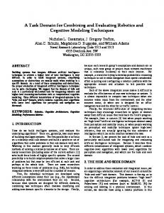
“faster” and “slower” are used to respectively double or half the speed of the current interaction task, changing the state of the system. These low level interaction techniques are normally encompassed by more complex interfaces that define how these system control techniques fit together. These encompassing, complex interfaces are known as system control interfaces (SCIs). The ring menu [Liang and Green 1994, Shaw and Green 1994], the TULIP menu [Bowman and Wingrave 2001], and the command and control cube (C3) [Grosjean et al. 2002] are all examples of SCIs. All of these interfaces define how the user transitions between system control techniques and interaction tasks. For instance, the C3 is a 3 x 3 x 3 cubic grid, where each of the 27 grid cubes is a menu item (Figure 1.1). For the example task of changing the mode of interaction to a pencil tool, the user activates the menu by making a pinch on a Pinch GloveTM worn on the non-dominant hand, and the C3 appears centered at the user’s hand. The user then moves her hand in the direction of the pencil menu item cube relative to the center position, and then releases the pinch to change the mode of interaction to the pencil tool.
Figure 1.1
The command and control cube is an example of a system control interface. (The C3 pictured here is not the original developed by Grosjean et al.)
Ryan P. McMahan
Chapter 1 Introduction
3
System control interfaces are important for controlling the flow of interaction in an application and hence can make or break an application. In [Bowman et al. 2005], several design guidelines for 3D system control are presented: •
Avoid disturbing the flow of action of an interaction task.
•
Prevent unnecessary changes of the focus of attention.
•
Avoid mode errors.
•
Use an appropriate spatial reference frame.
•
Structure the functions in an application.
•
Consider using multimodal input.
These guidelines suggest that SCIs for IVEs should be transparent – these interfaces should induce minimal cognitive effort so that users can focus on what to do instead of how to do it. A transparent SCI would maximize user performance and productivity by minimizing the cognitive effort required to interact with the interface itself and keeping the user focused on his current task. Despite how important these interfaces are, there has unfortunately been a relative lack of empirical evaluations of SCIs [Bowman et al. 2005]. 1.2 Creating a Testbed for System Control Interfaces Techniques for other 3D interaction tasks, such as selection, manipulation, and travel, have been empirically evaluated through testbed evaluations. Testbeds are environments and tasks that involve all of the important aspects of a task, test each component of a technique, consider outside influences on performance, and have multiple performance measures [Bowman et al. 2001]. Testbed evaluations allow multiple interaction techniques for the same type of task to be evaluated equally under several sets of circumstances. There are several benefits of testbed evaluations. One benefit is reusability [Bowman et al. 2001]. If a new technique for a given interaction task is developed, that technique may be run through the testbed for that task and compared against previously tested techniques. This saves time later in comparing new interaction techniques to previously established techniques. Another benefit of testbed evaluations is the complex performance data generated from multiple
Ryan P. McMahan
Chapter 1 Introduction
4
independent and dependent variables [Bowman et al. 2001]. This data allows discoveries to be made of interesting interactions between variables that would not have emerged from standard usability evaluations. Because the benefits of testbed evaluation are so great and there has been a relative lack of empirical evaluations of system control, it would be reasonable and useful to build a testbed for SCIs. Such a testbed would provide an empirical method for evaluating and comparing current SCIs in detail. This would lead to guidelines for choosing a SCI based on a particular application scenario. Additionally, as future SCIs are developed, reusability would allow a new SCI to be compared to the previously established SCIs by running formal experiments solely for the new SCI. Unfortunately there are currently major problems in creating a testbed for SCIs. One problem is that comparing two SCIs is like comparing apples and oranges. SCIs have different styles of interaction which makes their comparison difficult. For instance, some interfaces are based on graphical menus, such as the Virtual-SAP application [Bowman et al. 2003], while others can be based on gestural input for issuing commands, such as Polyshop [Mapes and Moshell 1995]. Comparing visual interfaces, such as menus, to non-visual interfaces, such as gestures, would be extremely complex, and it would be difficult to eliminate confounds for testbed evaluation. For example, the system control task of confirming an action could be accomplished by selecting an “OK” button on an adapted 2D menu or by using a “thumbs-up” posture with the hand. The performance times required to complete these two different confirmations can obviously be compared, but there are hidden confounds in using these two different techniques in a SCI. One obvious confound is feedback. In the example of the “OK” button, the system is obviously awaiting confirmation for an action, but in the example of the “thumbs-up” posture, unless other feedback is provided, the user may be unaware that confirmation is required. Another major problem with creating a SCI testbed is that usually a SCI does not dictate how it is should be used. For example, an adapted 2D menu interface could be used to issue commands in at least two ways. Assume the user wants to remove an object from the environment. The user could select a “Remove” button from the menu and then select the object he wants to remove.
Ryan P. McMahan
Chapter 1 Introduction
5
Alternatively, the user could select the object to remove first and then select the “Remove” button from the menu. Because a SCI doesn’t dictate how it should be used, two developers may create two different flows of interaction for an application despite using the same interface. This causes problems for creating a testbed evaluation for SCIs, as the same SCI could be evaluated in more than one way. Since creating a testbed evaluation for SCIs would be extremely beneficial to 3DUI designers, these major problems need to be addressed. For this research, we address the second major problem mentioned here, which is directly related to task sequences, in hopes of advancing towards a testbed for SCIs. By determining how SCIs should dictate their usage, we can create guidelines for using SCIs and provide standards for a testbed evaluation. 1.3 Task Sequences A task sequence is the order of operations in a system control task [McMahan and Bowman 2007]. For example, if performing a particular function requires the indication of an object within the IVE and the indication of the function itself, then there are two obvious task sequences for performing the function. One task sequence would be the indication of the function followed by the indication of the object. An example of this would be a user selecting a “Remove” button from an adapted 2D menu and then selecting a virtual tree to remove from the environment (Figure 1.2A). We refer to this task sequence as an Action-Object task sequence because the user indicates the action before the object. The second obvious task sequence would be the indication of the object followed by the indication of the function. In the example, the user selects the virtual tree and then selects the “Remove” button from the menu (Figure 1.2B). This is referred to as an Object-Action task sequence because the user indicates the object before the action.
Ryan P. McMahan
Chapter 1 Introduction
6
A
B
Figure 1.2
Examples of A) the Action-Object task sequence and B) the Object-Action task sequence.
As mentioned in Section 1.2, a SCI doesn’t dictate how it should be used. Specifically, a SCI can be used in as many or more ways to complete a task as there are task sequences for that task. If task sequences for 3D tasks were standardized, or if their effects were understood, one confound for comparing SCIs could be eliminated, which would bring us one step closer to creating a testbed for such interfaces. In conventional environments, such task sequence standards have already been adopted. In most command line interfaces (CLIs), a user types a command first followed by a list of parameters. We correlate this standard for CLIs with the Action-Object task sequence since the user first indicates the action (the command) and then objects (the parameters). In most GUIs, a user clicks on a target icon first and then accesses menus to execute commands on the target. We correlate this standard for GUIs with the Object-Action task sequence since the user first indicates the object (the icon) and then the action (the menu command). Both of these
Ryan P. McMahan
Chapter 1 Introduction
7
conventional environments use different standard task sequences, which leads us to question if and which task sequences should be standardized for IVEs. If a single task sequence is optimal for usability, then any SCI would benefit from using that sequence and establishing a standard task sequence would be quite obvious. On the other hand, if different task sequences provide high levels of usability in different situations, understanding the combined effects of task sequence and task would still be beneficial for IVE designers. This research focuses on evaluating task sequences in regard to usability, with the goal of potentially standardizing task sequences for SCIs. By establishing a standard for task sequences, we could eliminate one confound for comparing these interfaces and would be closer to establishing a testbed for SCIs. 1.4 Research Questions In the course of our research we have developed several research questions regarding the design of system control interfaces and the use of task sequences. We directed our research to answer the following questions. 1. How do task sequences affect user performance in immersive virtual environments? One part of determining the usability of an interface is evaluating the effect that that interface has on the user’s performance. Since underlying task sequences can affect the interaction flow of an interface, do different task sequences change the effect that an interface has on user performance? Do different sequences of indications affect how the user thinks about the task and in turn affect the performance of the user? Do some task sequences induce less cognitive effort than others? 2. Which task sequences do users prefer in immersive virtual environments? Another consideration in determining the usability of an interface is assessing user preference. Do most users prefer one task sequence over others and why? Are some task sequences easier to
Ryan P. McMahan
Chapter 1 Introduction
8
understand for users than others? Do novices prefer the same task sequences as experienced users or do task sequence preferences evolve with expertise? 3. Is there a single task sequence that should be utilized by system control interfaces for immersive virtual environments and be accepted as the standard task sequence? As mentioned in Section 1.3, CLIs typically utilize the Action-Object task sequence, and GUIs typically utilize the Object-Action task sequence. As of now, there is not a standard task sequence utilized by SCIs for IVEs. Should SCIs for IVEs utilize the Action-Object task sequence or the Object-Action task sequence? What should determine which task sequence to accept as the standard for SCIs? 1.5 Hypotheses We formed the following hypotheses about system control interfaces and task sequences based on the similarities of immersive virtual environments to graphical user interfaces and our experiences with virtual environment applications. 1. The Object-Action task sequence will induce less cognitive effort than the Action-Object task sequence and will improve user performance. With the Object-Action task sequence, users begin tasks by indicating an object, a concrete representation. With the Action-Object task sequence, users begin by indicating an action, an abstract concept. We hypothesize that task sequences beginning with the indication of a concrete representation will induce less cognitive effort for users than those beginning with the indication of an abstract concept, hence the Object-Action task sequence will induce less cognitive effort than the Action-Object task sequence. Following from this, we also hypothesize that the ObjectAction task sequence will result in higher levels of user performance.
Ryan P. McMahan
Chapter 1 Introduction
9
2. Novices and experienced users will both prefer the Object-Action task sequence for working in an immersive virtual environment. In comparison to CLIs and GUIs, IVEs are more similar to GUIs. In CLIs, strings are used to represent everything, including commands, objects, and parameters. In GUIs, objects are visually represented by icons and commands are contained in graphical menus. In IVEs, objects have their own visual representations, which make IVEs more similar to GUIs than CLIs. Additionally, most people commonly use GUIs over CLIs. Due to the similarities and familiarities that GUIs and IVEs share, we hypothesize that novices will prefer the Object-Action task sequence for working in an IVE. Based on our own experiences with IVEs, we hypothesize that experienced users will also prefer the Object-Action task sequence for working in an IVE. 3. The Object-Action task sequence should be the standard task sequence utilized by system control interfaces for immersive virtual environments. Because both CLIs and GUIs have standard task sequences, we hypothesize that there is a single task sequence that should be the standard for SCIs. Since we hypothesized that the Object-Action task sequence will induce less cognitive effort than the Action-Object task sequence and that the Object-Action task sequence will be preferred by novices and experienced users over the ActionObject task sequence, we hypothesize that the standard task sequence for SCIs should be the Object-Action task sequence. 1.6 Approach We used the following approach to answer our research questions and test our hypotheses.
Ryan P. McMahan
Chapter 1 Introduction
10
1. Develop a method to evaluate the effects of task sequence on user performance. One problem in evaluating the effects of task sequence on user performance is that absolute task performance is dependent on the SCI used to evaluate the task sequence. It is possible that a SCI could bias the absolute task performance of one task sequence over another due to the design and implementation of the SCI. Consider two different 2D adapted menu SCIs. The first SCI uses a window statically located in front of the user at all times. The second SCI uses a window that dynamically moves to the last location the user pointed to within the IVE. The first SCI is biased for the Action-Object task sequence as the user will always start by focusing ahead. Additionally, for the Object-Action task sequence, this first SCI forces the user to return focus to the same location, no matter where the object is. The second SCI is biased for the Object-Action task sequence as the user is able to quickly access the window near the object. For the Action-Object task sequence, this second SCI forces the user to search in the location of the last object before beginning a new task. Since the SCI used to evaluate task sequences could be biased, an alternative method to absolute task performance comparison for evaluating the effects of task sequence on user performance is necessary. One alternative is to compare the cognitive effort induced by each task sequence. This eliminates any effects that a specific implementation of a SCI may have on the evaluation of a task sequence. Unfortunately it is difficult to measure cognitive effort. Because we don’t know exactly what the user is thinking, it is hard to determine how much of the user’s cognitive effort is used to think about the task sequence and how much is used to think about interacting with the SCI. To alleviate this problem, we will develop a model similar to the Keystroke-Level Model (KLM) [Card et al. 1980] and use a cognitive effort operator similar to the mental operator. We can estimate the cognitive effort operator by subtracting all other operators from the total time to complete a task. The other operators include the physical (perceptual and motor) time required for the user to make all of the indications required by the task and the cognitive time required for the user to interact with the SCI.
Ryan P. McMahan
Chapter 1 Introduction
11
Since we need to know the physical and cognitive time required to interact with the SCI for a task, we need a single system control interface for evaluating the effects of task sequence on user performance. We chose to use the Virtual Environment Windowing Library (VEWL) [Larimer and Bowman 2003]. VEWL is an adapted 2D menu SCI (Figure 1.3) developed on top of DIVERSE [Kelso et al. 2002]. Different from most adapted 2D menu interfaces, VEWL utilizes a virtual sphere and maintains all windows tangent to this sphere. This ensures that all windows are equal distance to the user and provides a virtual surface for the users to move the windows along.
Figure 1.3
The Virtual Environment Windowing Library (VEWL).
We ran two experiments to establish the data necessary to complete our new model and evaluate the effects of task sequence on user performance. The first experiment was used to estimate the time required to complete certain system control tasks with the chosen VEWL SCI based solely on atomic-level interactions such as clicking a command button and invoking a popup menu. This helped establish the expected physical and cognitive times required to interact with the SCI for a task. Ryan P. McMahan
Chapter 1 Introduction
12
The second experiment was used to estimate the total time required to complete a task in a chosen IVE and all other operators, such as selecting an object within the virtual environment. This information was then used with the data established in the first experiment to estimate the cognitive effort operator by subtracting all other operators from the total time required to complete a task. Hence, we were able to evaluate the effects of task sequence on user performance by comparing cognitive effort operators. 2. Develop an approach to capture user preferences for task sequences as their expertise increases. Since we are concerned with the user preferences of novices and experienced users for task sequences, we ran a longitudinal study to capture the preferences of users as their expertise with an IVE application increased. We designed an application with a single SCI that supports multiple task sequences so that users would have open preferences and would not be influenced on which task sequence to use. 3. Create guidelines for using task sequences with system control interfaces for immersive virtual environments and establish a standard task sequence. Using the information gathered in approaches #1 and #2, we formed guidelines on which task sequences should be used for designing, evaluating, and comparing SCIs. These guidelines will contribute to the development of a testbed for SCIs. 1.7 Overview In this thesis, we examine questions surrounding task sequences and SCIs, focusing on user performance and preference. In Chapter 2, we cover previous research on 3DUIs and work related to task sequences. In Chapter 3, we identify three different levels of task sequences and two different foci for task sequences. In Chapter 4, we explain different approaches to evaluating task sequences in full detail. In Chapter 5, we describe the first experiment, which was used to gather atomic-level performance data on using VEWL. In Chapter 6, we describe the second
Ryan P. McMahan
Chapter 1 Introduction
13
experiment, which was used to gather the remaining performance data necessary to estimate the cognitive effort operator of various task sequences. In Chapter 7, we describe the final experiment, which was a longitudinal study used to gather user preference data as users progressed from novices to experienced users for using an IVE application. Finally, in Chapter 8, we discuss the implications of these studies and present some guidelines for using task sequences with SCIs for IVEs.
Ryan P. McMahan
Chapter 1 Introduction
14
Chapter 2 Related Work 2.1 System Control and 3D User Interfaces In 2D user interfaces, system control tasks are supported by the use of specific interaction styles, such as the WIMP (Windows, Icons, Menus, and Pointers) metaphor [Preece et al. 2002]. Many of these same interaction styles have also been adapted to 3DUIs, as seen with adapted 2D menus, but because these interaction styles may not be effective in all situations, we have already seen the development of non-conventional system control techniques [Bowman et al. 2005]. In this section, we describe both conventional and non-conventional system control techniques, discuss some possible classifications for these techniques, and provide some basic design guidelines for SCIs. 2.1.1 Conventional Techniques In 2D user interfaces, interaction elements such as dropdown menus, pop-up menus, tool palettes, radio buttons, and checkboxes are everywhere and most users are very familiar with these interaction techniques. These same conventional techniques have also been adapted to 3DUIs in the form of adapted 2D menus and 3D widgets. Adapted 2D menus are simple 3D adaptations of 2D menus and basically function in the same way as they do in desktop GUIs [Bowman et al. 2005]. Dropdown menus, popup menus, floating menus, and toolbars are some of the types of adapted 2D menus that have been developed. Most of these types of adapted 2D menus, including popup menus (Figure 2.1), are encompassed in VEWL, the SCI described for our approach in Section 1.6. Adapted 2D menus can be placed in virtual environments by several different means including world-fixed, view-fixed, object-fixed, and hand-held [Lindeman et al. 1999]. A world-fixed menu has an absolute, fixed position in the VE and will move in and out of the user’s view as the user approaches and leaves that position, respectively. A view-fixed menu has a fixed position relative to the user’s viewpoint and moves along within the VE as the user does. An object-fixed Ryan P. McMahan
Chapter 2 Related Work
15
menu has a fixed position relative to an object within the VE and moves as the object moves. A hand-held menu is a special type of object-fixed menu that is fixed relative to an object held in the user’s non-dominant hand for bimanual interaction techniques.
Figure 2.1 The VEWL popup menu is an example of a view-fixed, adapted 2D menu. The 3D widget is another adaptation of conventional system control techniques. Many 2D user interfaces utilize widgets for manipulations such as resizing windows, rotating selections, and adjusting parameters. The 3D widget takes advantage of the extra degree-of-freedom (DOF) available in a 3D environment to enable more complex interactions and better visual affordances. There are two kinds of 3D widgets: context-sensitive (collocated) and non-context-sensitive [Bowman et al. 2005]. Context-sensitive widgets are typically used for changing geometric parameters because the functionality of the widget is moved onto an object in the 3D environment, strongly coupling functionality and geometry. Figure 2.2 shows an example of a context-sensitive widget used in the Home Design application [Mackie et al. 2004] for resizing a door. Non-context-sensitive widgets are normally used for standard menu item selections, such as the command and control cube (C3) [Grosjean et al. 2002], mentioned in Section 1.1.
Ryan P. McMahan
Chapter 2 Related Work
16
Figure 2.2 A context-sensitive, 3D widget is used for resizing a door in the Home Design application. 2.1.2 Non-conventional Techniques In IVEs, users have to deal with input and output devices that are considerably different from the desktop, such as 6-DOF input devices instead of the standard keyboard and mouse. These differences create both new problems and new possibilities for the development of system control techniques for 3DUIs. Hence, non-conventional techniques have been discussed as appropriate replacements for system control [Bullinger et al. 1997]. The development of a non-conventional system control technique is normally linked to human factors, the input devices used, and the system- and application-level factors involved [Bowman et al. 2005]. Because of these factors, we have seen the development of several different types of non-conventional techniques, including ring menus, TULIP menus, gestural commands, and tools. A ring menu [Liang and Green 1994, Shaw and Green 1994] is normally attached to the user’s hand with menu items arranged in a circular pattern around it. With this non-conventional
Ryan P. McMahan
Chapter 2 Related Work
17
technique, the user rotates his hand until the desired item falls within a “selection basket” and then the user makes the selection [Bowman et al. 2005]. The performance of this type of ring menu depends on the physical movement of the hand and wrist. Hence, system control designers have sought alternatives for rotating such as using a button on an input device to rotate the desired item into position. Figure 2.3 shows an example of a double-basket ring menu with two green selection baskets.
Figure 2.3
A double-basket ring menu is used as a non-conventional technique.
TULIP (Three-Up, Labels In Palm) menus [Bowman and Wingrave 2001] are menus attached to a user’s hand by assigning menu items to different fingers using Pinch GlovesTM (Figure 2.4). With this non-conventional technique, the user creates a pinch between a finger and the thumb of the same hand to select the corresponding menu item. When more than four items are in a menu, the first three items are displayed, attached to the user’s index, middle, and ring fingers. The pinky finger is labeled “More,” and selecting this menu item moves the next three items in the menu onto the user’s fingers and the inactive items are displayed, in groups of three, on the palm of the virtual hand.
Ryan P. McMahan
Chapter 2 Related Work
18
Figure 2.4
TULIP menus use finger pinches to select menu items.
Gestural commands are another type of non-conventional system control techniques and were one of the first system control techniques used for IVEs. Gestural commands can be classified as either postures or gestures [Bowman et al. 2005]. A posture is a static configuration of the hand, whereas a gesture is a dynamic movement. The usability of gestural commands for system control depends on the number and complexity of the gestural commands as more gestures imply more learning for the user [Bowman et al. 2005]. Another type of non-conventional system control techniques are tools, both physical and virtual. The use of familiar (real-world) devices for 3D interaction provides directness of interaction because of the real-world correspondence and familiarity provided by the tool itself [Bowman et al. 2005]. Physical tools are a collection of real physical objects with corresponding virtual representations. A user can access a physical tool by simply picking it up and using it. Virtual tools have no physical instantiations but behave just as physical tools do.
Ryan P. McMahan
Chapter 2 Related Work
19
2.1.3 Classifying Techniques With such a spectrum of conventional and non-conventional system control techniques being developed, 3DUI researchers have attempted to classify system control techniques [Bowman et al. 2005, Lindeman et al. 1999]. We find the classification presented in [Bowman et al. 2005], see Figure 2.5, to be the most useful for understanding the similarities of 3D system control techniques.
Figure 2.5
One classification of system control techniques based on metaphors.
This classification is organized around four main metaphors – graphical menus, voice commands, gestural commands, and tools – influenced by the description of non-conventional control techniques in [McMillan et al. 1997]. For graphical menus, visual feedback is the key connection for system control techniques as users can see what choices there are to choose from. For voice and gestural commands, direct input and memory load are key aspects. Users are Ryan P. McMahan
Chapter 2 Related Work
20
normally required to remember all of the commands and are not presented with choices although access to a command is more direct than that of a hierarchical graphical menu. Tools are an interesting combination of the other metaphors. Tools provide visual feedback in their representations, act as direct input as they are used on other objects, and require users to remember how each tool functions. 2.1.4 Design Guidelines As mentioned in Section 1.1, several design guidelines for 3D system control techniques have been presented in [Bowman et al. 2005]. These guidelines are overall guidelines and in no way should these be considered the only guidelines for designing 3D system control techniques. Avoid disturbing the flow of action of an interaction task. System control is often integrated with another 3D interaction task. Because of this integration, system control techniques should be designed to avoiding disturbing the flow of action of an interaction task. Prevent unnecessary changes of the focus of attention. One of the major interruptions to a flow of action is a change of the focus of attention. This may occur when users have to cognitively or physically switch between the actual working area and a system control technique, or even when they must look away to switch devices. Avoid mode errors. It is important that the user knows which interaction mode is currently active. Providing clear feedback remedies these types of errors. Use an appropriate spatial reference frame. Placing a system control technique in an optimal position can make a big difference in its usability. If a technique is not visible at all, placed far away from the actual work area, or not oriented toward the user, user performance will be negatively affected. Also, system control techniques shouldn’t occlude the user’s view of the actual work area.
Ryan P. McMahan
Chapter 2 Related Work
21
Structure the functions in an application. Using hierarchical menu structures and contextsensitive system control are good techniques for structuring the functionality of an application. In some cases, it may make sense to place some of the system control functionality on another device, such as a PDA. Consider using multimodal input.
System control techniques that combine multiple input
streams can provide more fluid and efficient system control. Unfortunately, these guidelines do not directly address the issue of task sequence – the order of operations in a system control task. Additionally, there has been no evidence of empirical evaluations of task sequences in SCIs for IVEs. For this research, we want to establish guidelines involving task sequences for SCIs, in an attempt to standardize task sequences for a SCI testbed. In order to better understand task sequences for SCIs, it is instructive to consider how task sequences relate to other humancomputer interfaces. 2.2 Task Sequences in Other Human-Computer Interfaces When computers first emerged around the time of World War II, humans first started interacting with them using punch card machines and teletypes [Stephenson 1999]. For decades these already-existing technologies had been used for translating letters into bits and vice versa so it was quite natural for these devices to be grafted to computers as the first human-computer interfaces. These interfaces were initially used to batch process series of commands for programming purposes, but command languages and command line interfaces (CLIs) soon emerged. 2.2.1 Command Line Interfaces (CLIs) When terminals and CLIs (Figure 2.6) emerged, the use of command languages allowed for interactive computing, leaving the batch processing era behind. A command language is defined
Ryan P. McMahan
Chapter 2 Related Work
22
by the range of commands provided and their syntax [Newman and Sproull 1973]. The term – command language – infers that the underlying interface style is focused on commands or actions. For instance, using UNIX, a user would type in the command prompt “rm foo.txt” to remove a file named “foo.txt” from the current directory. This syntax shows that most CLIs force users to specify their actions first, followed by any parameters necessary to complete the actions. Since commands (or actions) are specified first and then parameters (or objects) in order to complete a task, we classify the task sequences underlying CLIs as Action-Object task sequences.
Figure 2.6
An example of a terminal for a CLI.
2.2.2 Graphical User Interfaces (GUIs) The first major advance toward GUIs was Sutherland’s Sketchpad, a graphical design program [Sutherland 1963]. Sutherland’s goal was to create a program that would make it possible for a person and a computer to “converse rapidly through the medium of line drawings.” Sutherland was one of the first to discuss the power of GUIs, the conception of a display as “sheets of paper”, the use of pointing devices, the virtues of constraint representations, and the importance of depicting abstractions graphically [Hutchins et al. 1985].
Ryan P. McMahan
Chapter 2 Related Work
23
As GUIs emerged, the idea of direct manipulation also emerged. The term direct manipulation was originally coined by Shneiderman and refers to systems having the following properties [Shneiderman 1998]: 1. Continuous representation of the objects and actions of interest with meaningful visual metaphors. 2. Physical actions or presses of labeled buttons, instead of complex syntax. 3. Rapid incremental reversible operations whose effect on the object of interest is visible immediately. The influence of these concepts and the idea of direct manipulation can be seen in the WIMP (Windows, Icons, Menus, and Pointers) metaphor [Preece et al. 2002], which was codified by the Xerox PARC team in the 1970s. The WIMP metaphor first appeared commercially in the Xerox 8010 Star system in 1981 and is used in most of the current desktop interfaces of today. Essentially, the WIMP metaphor defines a GUI for a 2D desktop environment (Figure 2.7).
Figure 2.7
An example of a desktop GUI using the WIMP metaphor.
In the WIMP metaphor, most objects have visual representations (icons) and users complete commands by acting upon those representations with pointers. Returning to the previous
Ryan P. McMahan
Chapter 2 Related Work
24
example, to remove a file named “foo.txt” from the current directory, a user would right click with a mouse device on the icon labeled “foo.txt” and then left click on a “Delete” command in a pop-up menu displayed near the icon of interest. Another common alternative for this example is for the user to click and drag the icon labeled “foo.txt” from the current folder (or directory) to the trashcan or recycling bin icon on the desktop. In this alternative example, the trashcan or recycling bin represents a command or action. This interface style of direct manipulation forces users to think about their objects of interest first and then the actions to carry out upon those objects. Since objects are specified first, followed by actions, in order to complete a task, we classify the task sequences underlying the WIMP metaphor as Object-Action task sequences. 2.2.3 Explaining the Evolution of Interfaces To help explain the evolution of GUIs from CLIs, Shneiderman [Shneiderman 1998] presented some of the beneficial points of GUIs: •
Novices can learn basic functionality quickly, usually through a demonstration by a more experienced user.
•
Experts can work rapidly to carry out a wide range of tasks, even defining new functions and features.
•
Knowledgeable intermittent users can retain operational concepts.
•
Error messages are rarely needed.
•
Users can immediately see whether their actions are furthering their goals, and, if the actions are counterproductive, they can simply change the direction of their activity.
•
Users experience less anxiety because the system is comprehensible and because actions can be reversed easily.
•
Users gain confidence and mastery because they are the initiations of action, they feel in control, and they can predict the system responses.
These benefits explain some of the reasons why interfaces have evolved from CLIs to GUIs, but these reasons are closely linked to direct manipulation and not the underlying task sequences of these two different interface styles.
Ryan P. McMahan
Chapter 2 Related Work
25
2.3 Motivation to Examine Task Sequences The evolution of GUIs from CLIs has been examined but the evolution of task sequences and the replacement of the Action-Object task sequence by the Object-Action task sequence have not been examined in the literature. Shneiderman [Shneiderman 1998] presents the example of knowing whether to drag a file to the trashcan or to drag the trashcan to the folder as a syntactic aspect of direct manipulation. Unfortunately, there has been little or no research on these syntactic aspects of direct manipulation and thanks to the WIMP metaphor, the Object-Action task sequence has emerged as the standard for 2D desktop environments, whether this task sequence is superior to the Action-Object task sequence or not. GUIs and 2D desktop environments have already been standardized with the Object-Action task sequence. Even if we could prove that the Action-Object task sequence would be a better syntactic choice for direct manipulation in these 2D desktop environments, it would be impossible to convince millions of users to change their standard conceptions of 2D desktop environments. However, immersive virtual environments have not been standardized with a task sequence. Because virtual reality is still an emerging technology with few everyday users, 3DUIs for IVEs have not been standardized yet. It is still possible to evaluate task sequences to determine if one syntactic approach is better than the other and to apply that evaluation towards setting standards for IVEs. This opportunity may allow us to set proper standards for the underlying task structures involved with interacting with an IVE application. Most importantly, establishing standards for task sequences for SCIs will bring us one step closer to creating a testbed for these interfaces.
Ryan P. McMahan
Chapter 2 Related Work
26
Chapter 3 Identifying Task Sequences 3.1 Identifying Tasks A task sequence is the order of operations in a system control task [McMahan and Bowman 2007]. We have already mentioned two types of task sequences in the previous chapters: the Action-Object task sequence and the Object-Action task sequence. With the Action-Object task sequence, the user identifies the action before identifying the object, and with the Object-Action task sequence, the user identifies the object before identifying the action. For this research, we wanted to identify all of the possible task sequences that may be used in a SCI for an IVE, before attempting to evaluate such sequences. To help identify possible task sequences, we first needed to consider as many different IVE tasks as possible. We surveyed the 3DUI mailing list (http://www.3dui.org), a discussion list with participation by researchers from around the globe, asking for basic user tasks and complex user goals that have been encountered in IVE applications. We specifically asked for lists of basic user tasks and how these encountered tasks were completed in regard to system control. We also asked for lists of complex user goals that require the combination of several basic user tasks and how these goals could be completed in regard to system control. From this survey (see Appendix A), we were able to compile the following list of basic user tasks: •
Place a predefined object within the environment
•
Dynamically create an object within the environment
•
Remove an object from the environment
•
Translate an object
•
Rotate an object
•
Scale an object
•
Change the visual properties of an object
•
Change the abstract properties of an object
•
View the abstract properties of an object
•
Copy an object
Ryan P. McMahan
Chapter 3 Identifying Task Sequences
27
We also gathered much more information on how these basic user tasks could be completed and on complex user goals comprised of these basic components, but we found the list of basic user tasks to be most beneficial to identifying task sequences. Using the list, we identified three levels of complexity for task sequences: simple, complex, and combination. Each level has multiple possible task sequences. Note that the task sequence does not specify how the SCI is designed, but only the sequence of selections the user must perform. We also classified task sequences by two different foci: object-oriented and location-oriented. 3.2 Simple Task Sequences The first level of complexity that we identified was simple task sequences. The majority of the basic user tasks compiled from the survey required the indication of an action and an object. Based on this fact, we determined that a simple task sequence would include only the indication of one action and one object. We restricted simple task sequences to the indication of one action and one object to avoid questions regarding the use of modes and multiple-object selections. We also considered the combination of the indication of the action with the indication of the object, but classified this task sequence in our third level of complexity – combination task sequences (Section 3.4). Therefore, we identified only two simple task sequences – the Action-Object task sequence and the Object-Action task sequence. To explain these task sequences again, consider the example of a user wanting to remove a bookshelf from an IVE. In the Action-Object task sequence, the user would indicate the “Remove” command, using the SCI, and then select the bookshelf to be removed. In the Object-Action task sequence, the user would select the bookshelf and then, using the SCI, indicate the “Remove” command. See Figure 3.1 for examples of SCIs that implement these simple task sequences (NOTE: These are not the only ways to implement SCIs for simple task sequences).
Ryan P. McMahan
Chapter 3 Identifying Task Sequences
28
A
B
Figure 3.1
Implementations of a remove command using A) the Action-Object task sequence and B) the Object-Action task sequence.
3.3 Complex Task Sequences The second level of complexity that we identified was complex task sequences. Some of the basic user tasks compiled from the survey required the indication of an action, an object, and one or more parameters. To simplify the process of identifying task sequences, we decided to assume that if a task required the indication of any number of parameters that all of those indications would be made simultaneously, and no task would require more than one indication for all of the parameters necessary to complete the task. Therefore, we determined that a complex task sequence would include the indication of one action, one object, and one parameter. Using the definition of a complex task sequence, six complex task sequences can be identified: •
Action-Object-Parameter
•
Object-Parameter-Action
•
Action-Parameter-Object
•
Parameter-Action-Object
•
Object-Action-Parameter
•
Parameter-Object-Action
Ryan P. McMahan
Chapter 3 Identifying Task Sequences
29
We decided to not evaluate three of these complex task sequences for our research: ObjectParameter-Action, Parameter-Action-Object, and Parameter-Object-Action. All three of these complex task sequences involve the indication of a parameter before the action that will utilize that parameter. Some applications may experiment with this feature, but for most IVE applications it does not make sense to have the user indicate a parameter before knowing which command the parameter will be used for. This is why we decided to consider only the ActionObject-Parameter, Action-Parameter-Object, and Object-Action-Parameter task sequences. Consider the task of rotating a piece of furniture within the IVE by 45o. In the Action-ObjectParameter task sequence, the user uses the SCI to indicate the “Rotate” command, selects the piece of furniture to rotate, and the uses the SCI again to indicate the “45o” parameter. In the Action-Parameter-Object task sequence, the user uses the SCI to indicate the “Rotate” command, followed by the “45o” parameter, and then selects the piece of furniture to rotate. In the ObjectAction-Parameter task sequence, the user selects the piece of furniture to rotate and then uses the SCI to indicate the “Rotate” command followed by the “45o” parameter. See Figure 3.2 for examples of SCIs that implement complex task sequences (NOTE: These are not the only ways to implement SCIs for complex task sequences).
Ryan P. McMahan
Chapter 3 Identifying Task Sequences
30
A
B
Figure 3.2
C
Implementations of a rotate command with a 45o parameter using A) the Action-
Object-Parameter task sequence, B) the Action-Parameter-Object task sequence, and C) the Object-Action-Parameter task sequence.
Ryan P. McMahan
Chapter 3 Identifying Task Sequences
31
3.4 Combination Task Sequences The third level of complexity that we identified was combination task sequences. Looking back to the tasks compiled from the survey, we decided that some of the indications required could be combined into single indications – creating combination task sequences. Using the same assumptions made with simple task sequences and complex task sequences about using only one of each type of indication, we identified the following combination task sequences (NOTE: “+” indicates a combination of the two adjacent indications into a single required indication): •
Action+Object
•
Object+Action+Parameter
•
Action+Object-Parameter
•
Object+Parameter-Action
•
Action-Object+Parameter
•
Object-Parameter+Action
•
Action+Object+Parameter
•
Object+Parameter+Action
•
Action+Parameter-Object
•
Parameter+Action-Object
•
Action-Parameter+Object
•
Parameter-Action+Object
•
Action+Parameter+Object
•
Parameter+Action+Object
•
Object+Action
•
Parameter+Object-Action
•
Object+Action-Parameter
•
Parameter-Object+Action
•
Object-Action+Parameter
•
Parameter+Object+Action
By eliminating equivalent task sequences, such as Action+Object-Parameter and Object+ActionParameter, we can reduce the list of identified combination task sequences to the following: •
Action+Object
•
Action+Object-Parameter
•
Action-Object+Parameter
•
Action+Object+Parameter
•
Action+Parameter-Object
•
Object-Action+Parameter
•
Object+Parameter-Action
•
Parameter-Action+Object
Ryan P. McMahan
Chapter 3 Identifying Task Sequences
32
We decided to not evaluate four of these complex task sequences for our research: Action+Object,
Action+Object+Parameter,
Object+Parameter-Action,
and
Parameter-
Action+Object. We decided not to evaluate the Action+Object and Action+Object+Parameter task sequences because we felt that these single indication task sequences would be difficult to implement in most SCIs. One possible implementation would be widgets attached to each object representing every possible combination of actions and parameters, but studying single selections is not very interesting research. We decided not to evaluate the Object+Parameter-Action and Parameter-Action+Object task sequences because the parameter is indicated before the action (see Section 3.3). Therefore, for combination task sequences, we only considered the Action+Object-Parameter, Action-Object+Parameter, Action+Parameter-Object, and ObjectAction+Parameter task sequences. To look at these combination task sequences closer, let us revisit the task of rotating a piece of furniture within the IVE by 45o. In the Action+Object-Parameter task sequence, the user would use the SCI to indicate the “Rotate” command and the piece of furniture to rotate at the same time and then use the SCI to indicate the “45o” parameter. For the Action-Object+Parameter task sequence, the user would use the SCI to indicate the “Rotate” command and then would use the SCI to indicate the piece of furniture to rotate and the “45o” parameter at the same time. For the Action+Parameter-Object task sequence, the user would use the SCI to indicate the “Rotate” command and the “45o” parameter at the same time and then would select the piece of furniture to rotate. In the Object-Action+Parameter task sequence, the user selects the piece of furniture to rotate and then uses the SCI to indicate the “Rotate” command and the “45o” parameter at the same time. Figure 3.3 shows examples of SCIs that implement combination task sequences. Note that these examples are not the only ways to implement SCIs for combination task sequences. Additionally, these examples may not be optimal for scalability. For instance, the example SCI for the ObjectAction+Parameter task sequence would be very unusable if an object had several functions and parameters associated with it. In this instance, the many 3D widgets would occlude the environment and each other.
Ryan P. McMahan
Chapter 3 Identifying Task Sequences
33
A
B
C
D
Figure 3.3
Implementations of a rotate command with a 45o parameter using A) the
Action+Object-Parameter task sequence, B) the Action-Object+Parameter task sequence, C) the Action+Parameter-Object task sequence, and D) the Object-Action+Parameter task sequence.
Ryan P. McMahan
Chapter 3 Identifying Task Sequences
34
3.5 Foci of Task Sequences For the previous sections on simple, complex, and combination task sequences, the task sequences discussed address object-oriented tasks. In IVEs, some tasks may not involve an object but instead a location within the environment. This fact caused us to classify task sequences by two different foci: object-oriented and location-oriented. Location-oriented task sequences are the same as their object-oriented counterparts except that the user selects a location within the IVE instead of selecting an object. For example, consider the task of placing a cube within the VE. The location-oriented version of the Action-Parameter-Object task sequence for this task would have the user use the SCI to indicate a place command followed by a cube parameter, and then the user would select the desired location of the cube in the environment. By classifying task sequences as object-oriented or location-oriented, we essentially double the number of task sequences identified. We could re-list all of the task sequences, replacing the term “Object” with “Location”. For example, we could talk about the Action-Location and Location-Action task sequences. To avoid doubling our lists, we simply refer to location-oriented task sequences by their object-oriented counterparts and note the foci, location-oriented. Therefore, a task sequence that involves the indication of an action and then a location would be referred to as a location-oriented Action-Object task sequence. The decision to choose “Object” over “Location” was based on the greater number of object-oriented basic user tasks than location-oriented basic user tasks. Another consideration about the foci of a task sequence is that location-oriented combination task sequences are extremely hard to implement with a SCI. Consider the Action+ObjectParameter combination task sequence. For an object-oriented version of this task sequence, simple 3D widgets solve the design problem of combining the indication of the action and the object into a single indication (see Figure 3.3A). For a location-oriented version of this task sequence, if 3D widgets were used, the entire virtual environment would be cluttered with widgets that would occlude the environment itself and each other. For this reason, we decided to not consider location-oriented combination task sequences for our research, since this is impractical for SCIs to implement.
Ryan P. McMahan
Chapter 3 Identifying Task Sequences
35
3.6 Summary In this chapter, we have identified the following possible task sequences for SCIs: Simple Task Sequences •
Action-Object
•
Object-Action
Complex Task Sequences •
Action-Object-Parameter
•
Action-Parameter-Object
•
Object-Action-Parameter
•
Object-Parameter-Action
•
Parameter-Action-Object
•
Parameter-Object-Action
Combination Task Sequences •
Action+Object
•
Action+Object-Parameter
•
Action-Object+Parameter
•
Action+Object+Parameter
•
Action+Parameter-Object
•
Object-Action+Parameter
•
Object+Parameter-Action
•
Parameter-Action+Object
Additionally, we identified two classifications for task sequences: object-oriented and locationoriented.
Ryan P. McMahan
Chapter 3 Identifying Task Sequences
36
We have also explained our rationale for considering only the following task sequences for our research: Simple Task Sequences •
Action-Object (object- and location-oriented)
•
Object-Action (object- and location-oriented)
Complex Task Sequences •
Action-Object-Parameter (object- and location-oriented)
•
Action-Parameter-Object (object- and location-oriented)
•
Object-Action-Parameter (object- and location-oriented)
Combination Task Sequences •
Action+Object-Parameter (object-oriented only)
•
Action-Object+Parameter (object-oriented only)
•
Action+Parameter-Object (object-oriented only)
•
Object-Action+Parameter (object-oriented only)
Ryan P. McMahan
Chapter 3 Identifying Task Sequences
37
Chapter 4 Evaluating Task Sequences 4.1 Motivation As mentioned in Section 1.3, this research focuses on evaluating task sequences in regard to usability, with the goal of potentially standardizing task sequences for SCIs. By establishing a standard for task sequences, we could eliminate one confound for comparing these interfaces and would be closer to establishing a testbed for SCIs. The first step in evaluating task sequences is to decide what to evaluate and how to accomplish that evaluation. In the course of our research we attempted to evaluate task sequences using three different methods. These three methods focused on user instincts (Section 4.2), user performance (Section 4.3), and user preferences (Section 4.4). We decided to focus upon these user aspects because they all affect and contribute to usability. 4.2 User Instincts for Task Sequences The first method of evaluating task sequences that we considered was focused on user instincts for task sequences. We believe that for certain tasks a user will have inherent ideas of how to achieve these tasks. For instance, for the task of moving a chair across a room, the user might break down the task into the subtasks of picking up the chair, carrying the chair to the desired location, and then setting the chair back down. If this breakdown was an inherent idea for everyone, it could be considered an instinct, specifically a task sequence instinct. The concept of task sequence instincts also contributes to the concept of making 3DUIs more natural, which researchers have been striving for in the past few years. If task sequence instincts exist, then 3DUIs that conform to these inherent ideas of how to complete certain tasks would be more natural. By making more natural 3DUIs, user performance and usability improve as users know what to expect of and how to interact with these interfaces.
Ryan P. McMahan
Chapter 4 Evaluating Task Sequences
38
With the possible benefits of determining task sequence instincts in mind, we set out to design an experiment to evaluate user instincts for task sequences. Specifically, we wanted to determine if users have instincts about completing certain types of tasks. We decided to reuse the list of basic user tasks from Section 3.1 as a list of tasks to evaluate user instincts for, but we still did not know how to evaluate task sequence instincts. Our first experimental design was to present a simple SCI that users would be free to decide how to use for completing a task. Consider the task of removing an object from the environment. We could present the user with an adapted 2D menu with a single button labeled “Remove”, a single object within the environment to be removed, and a verbal directive of the task. If the user had an Action-Object task sequence instinct for this remove task, the user would presumably select the “Remove” button first and then select the object. If the user had an Object-Action task sequence instinct, the user would presumably select the object first and then the “Remove” button.
Figure 4.1
First experimental design for evaluating task sequence instincts.
This initial experimental design for evaluating user instincts for task sequences seemed promising until we began developing the details of the experiment. The major problem we encountered was how to eliminate interface affordances. For instance, people tend to notice large objects before smaller objects. Therefore in the aforementioned interface, if the “Remove” button was larger than the object to be removed, the interface affords an Action-Object task sequence as the user will probably notice the action before the object. On the other hand, if the object to be Ryan P. McMahan
Chapter 4 Evaluating Task Sequences
39
removed was larger than the “Remove” button, then the interface affords an Object-Action task sequence. There are several other types of affordances to consider: people tend to read left to right, people tend to read top to bottom, people notice closer objects before objects farther away, and people notice highly contrasted objects before objects that have little contrast with the background. We attempted to address the major problem of interface affordances but found that stripping away these affordances is a daunting task. Deciding where to place a menu in relation to the object of focus is the most daunting part of this task. If the menu is placed to the left of the object or above the object, the interface affords an Action-Object task sequence. If the menu is placed to the right of the object or below the object, the interface affords an Object-Action task sequence. Regardless of the position of the menu, the interface will afford one task sequence over another. One idea would be to balance other affordances, such as making objects larger or using higher contrasts, with menu position. Unfortunately, it is impossible to determine that balance as some users may be more affected by menu position while others may be more affected by larger objects. Due to the affordances that interfaces provide and our inability to strip away these affordances, we decided to abandon our first experimental design. Instead, we began to pursue an alternative experimental design using “think-aloud” exercises and no SCI at all. The concept behind our second experimental design was to present the user with a verbal description of a situation and a task to complete in that situation, and then have the user explain how they would complete the task. An example of such a think-aloud exercise would be “There is a cube in front of you that you want to paint red. How would you complete this task?” Some possible responses may be “Use a paintbrush and paint it red” or “Pick up the cube and dip it in red paint.” Unfortunately there were problems with this experimental design as well. The most important problem discovered was that how the task is verbally communicated to the user can affect how the user thinks about the task. Telling the user “there is a cube in front of you that you want to paint red” suggests an Object-Action task sequence to the user since the object is mentioned to the user before the action. Alternatively, telling the user “you want to paint a cube in front of you
Ryan P. McMahan
Chapter 4 Evaluating Task Sequences
40
red” suggests an Action-Object task sequence since the action is mentioned to the user before the object. Another problem with this experimental design would have been correlating user responses to task sequences. For example, what task sequence would “use a paintbrush, pick up the cube, and paint it” correlate to? Since our first experimental design failed to strip away interface affordances and our second experimental design failed to provide a non-biased form for presenting tasks, we decided to abandon the entire evaluation of user instincts for task sequences. We still believe that task sequence instincts may exist and would give great insight for designing 3DUIs, but we were unable to successfully evaluate such instincts. 4.3 Effects of Task Sequences on User Performance The second method of evaluating task sequences that we considered was determining the effects of task sequences on user performance. User performance is closely tied to usability and is often considered the most important factor of usability. Often absolute user performance – how long it takes a user to complete a task – is used as a metric for user performance evaluations. Unfortunately, because absolute task performance is dependent on the SCI used to evaluate the task sequence, there is a problem in evaluating the effects of task sequence on absolute task performance. A SCI can bias the absolute task performance of one task sequence over another due to the design and implementation of the SCI as seen in the example from Section 1.6 of the two different 2D adapted menu SCIs. The first SCI – a statically located window – is biased for the Action-Object task sequence since the user will always start by focusing ahead and, for the Object-Action task sequence, the SCI forces the user to return focus to the same location, no matter where the object is. The second SCI – a dynamically located window – is biased for the Object-Action task sequence since the user is able to quickly access the window near the object and, for the Action-Object task sequence, the SCI requires the user to search in the location of the last object before beginning a new task.
Ryan P. McMahan
Chapter 4 Evaluating Task Sequences
41
Since the SCI used to evaluate task sequences could be biased, an alternative method to absolute task performance comparison for evaluating the effects of task sequence on user performance is necessary. An alternative is to compare the cognitive effort induced by each task sequence. This eliminates any effects that a specific implementation of a SCI may have on the evaluation of a task sequence and provides generalized results. Unfortunately it is difficult to measure cognitive effort because we do not know exactly what the user is thinking. It is hard to determine how much of the user’s cognitive effort is used to think about the task sequence and how much is used to think about interacting with the SCI. To alleviate this problem, we developed a model similar to the Keystroke-Level Model (KLM) [Card et al. 1980]. The KLM was proposed as a model for predicting the time it takes an expert user to perform a given task on a given computer system. The model is based on counting keystrokes and other low-level operations, including the system’s responses and the user’s mental preparations. The KLM asserts that executing a task can be described in terms of four different physical-motor operators (keystroking, pointing, homing, and drawing), one mental operator (by the user), and one response operator (by the system). Execution time is simply the sum of the time for each of these operators, as seen in Equation 4.1.
TExecute = TK + TP + TH + TP + TM + TR
(4.1)
Using a similar concept, we created a model which defines the total time to complete a system control task as the sum of the time for the perceptual and motor processes needed to select the necessary components (action, object, and parameter) and the cognitive time induced by the underlying task sequence (Equation 4.2). These times are not necessarily non-overlapping as humans are able to perform actions while thinking about other tasks. For example, a user could think of the next indication to perform in the middle of moving his arm to perform the current indication. Regardless, we are still accounting for the additional time required when the user is forced to think about the current task sequence.
TTotal = TPerceptual-Motor + TCognitive
Ryan P. McMahan
Chapter 4 Evaluating Task Sequences
(4.2)
42
Using our model for user performance, we are able to estimate the cognitive time induced by a task sequence by subtracting the estimated time to make all necessary selections from the total time the user required to complete the task. For example, consider the task of removing a cube from the IVE. If the user takes 1.0 second to perceptually recognize and physically select the SCI component for the remove command and takes 1.0 second to perceptually recognize and physically select the cube, then TPerceptual-Motor is 2.0 seconds. If the user takes a total time, TTotal, of 2.5 seconds to remove the cube from the IVE, then the cognitive time induced by the task sequence, TCognitive, is 0.5 seconds. An important factor in this calculation is the accuracy of estimating TPerceptual-Motor. Specifically we need to know the cognitive and physical time required to interact with the SCI for a task. Therefore a single SCI for evaluating the effects of task sequence on user performance was necessary for our research. As mentioned in Section 1.6, we chose to use the Virtual Environment Windowing Library (VEWL) [Larimer and Bowman 2003]. VEWL is a viewfixed, adapted 2D menu SCI developed on top of DIVERSE [Kelso et al. 2002] that utilizes a virtual sphere to provide a surface for moving windows around. We designed our first experiment (see Chapter 5) to establish estimates for the time required to complete certain system control tasks with the VEWL SCI based solely on atomic-level interactions, such as clicking a command button and moving a window. This experiment established the expected cognitive and physical times required to interact with VEWL for various system control tasks. We then designed a second experiment (see Chapter 6) to obtain an average for the total time required to complete various tasks in an IVE application. By subtracting TPerceptual-Motor, established in the first experiment, from TTotal, established in the second experiment, we estimated TCognitive for different task sequences. By estimating TCognitive of the task sequences we identified in Chapter 3, we were able to compare these values to determine which task sequences should be used for certain tasks. More importantly, we were able to evaluate the effects of task sequences on user performance. Chapter 6 covers these results in detail.
Ryan P. McMahan
Chapter 4 Evaluating Task Sequences
43
4.4 User Preferences for Task Sequences The third method of evaluating task sequences that we considered was determining which task sequences users prefer. User preference is a highly regarded aspect of usability within the human-computer interaction community. Sometimes developers will even design systems that have multiple methods of completing the same task as to provide users the ability to decide which method to use. For example, in most applications there are three standard methods to save a current document – accessing the “Save” command from the “File” menu, clicking on a save icon, or using the “Ctrl + S” keyboard shortcut. Providing different methods to complete the same task increases usability as users chose methods they prefer and understand best. For this research, we were concerned with two aspects of user preferences – which task sequences novices prefer and how those preferences evolve as novices become experienced users. If the majority of novices prefer the same task sequences, then SCIs that utilize those task sequences should be easier for novices to learn than SCIs that utilize other task sequences. Hence, these SCIs would be more usable and more natural for novices. Additionally, if we track the evolution of task sequence preferences as novices become experienced users, we can determine the range of task sequences that SCIs should provide. For instance, if novices prefer the Action-Object task sequence and this preference evolves to the Object-Action task sequence, then SCIs should provide methods for using either task sequence, to accommodate novices and experienced users alike. On the other hand, if novices and experienced users both prefer the Action-Object task sequence then SCIs would be able to utilize a single task sequence without causing much detriment. In order to evaluate which task sequences novices prefer and how those preferences evolve, we designed a longitudinal study of five sessions in which users would have choices of which task sequences to use for completing tasks (see Chapter 7). The SCI for this experiment was designed to support multiple task sequences so that users would have open preferences and would not be influenced on which task sequence to use. Throughout the sessions, we were able to record the preferences of the participants, capturing data on novices and the evolution of their preferences as they became experienced users. Chapter 7 covers the results of this study in detail.
Ryan P. McMahan
Chapter 4 Evaluating Task Sequences
44
4.5 Summary In this chapter, we presented three different methods for evaluating task sequences. Our first method was concerned with task sequence instincts, inherent ideas shared by users about which task sequences should be used for certain tasks. Unfortunately, we were unable to design an experiment to evaluate task sequence instincts due to inabilities to strip away interface affordances and avoid biased directions for think-aloud exercises. Our second method for evaluating task sequences was concerned with user performance. Specifically, to evaluate the effects of task sequence on user performance, we examined the cognitive effort induced by task sequences. We were able to estimate these cognitive effort by building a task model (see Equation 4.2) very similar to the KLM. Our third method for evaluating task sequences was concerned with user preferences. By providing choices for which task sequences to use and capturing data from several sessions of a longitudinal study, we were able to evaluate user preferences for task sequences.
Ryan P. McMahan
Chapter 4 Evaluating Task Sequences
45
Chapter 5 VEWL Performance Study 5.1 Virtual Environment Windowing Library As mentioned in Section 4.3, for evaluating the effects of task sequences on user performance, we decided to use the Virtual Environment Windowing Library (VEWL) [Larimer and Bowman 2003] for the SCI. Different from most adapted 2D menu interfaces, VEWL utilizes a virtual sphere as a surface for content to be maintained tangent to and to be moved along. This ensures that all windows and widgets are equal distance to the user and allows for placement of content anywhere around the user. Users can “click on” these windows and widgets using ray-casting and the VEWL mouse, an adapted 2D mouse that moves along the inside of the virtual sphere. Windows are perhaps the most important widget in VEWL. These widgets are view-fixed, adapted 2D windows that enable all of the other VEWL widgets aside from popup menus. VEWL windows remain tangent to the VEWL virtual sphere at all times, but can be moved along the surface of the virtual sphere by the user. A VEWL window also has a single button in the upper left corner for closing or removing the window. A VEWL window can be seen in Figure 5.1.
Figure 5.1
Ryan P. McMahan
A VEWL window enabling no other widgets.
Chapter 5 VEWL Performance Study
46
Aside from windows, VEWL supports several widgets including checkboxes, command buttons, dropdown menus, and scrolling lists. The VEWL checkbox widget is nearly identical to the checkbox widgets found in most desktop GUIs. The checkbox has two main parts – a box which can appear checked or unchecked and a label which may contain a string to identify the widget (see Figure 5.2). Both the box and the label can be clicked once to change the state of the checkbox from unchecked to checked or vice versa.
Figure 5.2
VEWL checkboxes can be unchecked or checked.
The VEWL command button widget is equivalent to the standard buttons found in most desktop applications. The command button is presented as a raised rectangular box on a VEWL window and may either be textured with a pattern or contain a label to help identify the widget (see Figure 5.3). Command buttons are normally clicked once to execute or indicate a command or system control task.
Figure 5.3 Ryan P. McMahan
VEWL command buttons are used to execute or indicate commands. Chapter 5 VEWL Performance Study
47
The VEWL dropdown menu widget is similar to the dropdown menus found in most desktop applications. The widget has two states and consists of several parts. The first dropdown menu state is non-activated. During this state, the dropdown menu appears as a single widget with a label representing the item selected from the menu and a down arrow indicating that the widget can be activated (see Figure 5.4A). The second dropdown menu state is activated. During this state, the dropdown menu appears as a list of items with several mini-widgets, similar to a scrollbar, located on the right side of the list. There are a total of five mini-widgets that are used to scroll the list (see Figure 5.4B). The first mini-widget is the UpArrow and moves the list up by one single item when clicked. Below the UpArrow is the PageUp, which moves the list up by an entire page when clicked. The middle mini-widget is the CurrentPage, which only indicates the location of the current page within the entire list. The PageDown mini-widget is below the CurrentPage and moves the list down by an entire page when clicked. The last mini-widget is the DownArrow, which moves the list down by a single item when clicked. Once an item in the list has been clicked, the dropdown menu changes state from activated back to non-activated. A
Figure 5.4
B
VEWL dropdown menus have A) non-activated states and B) activated states.
The VEWL scrolling list widget is essentially equivalent to a VEWL dropdown menu in activated state. Like VEWL dropdown menus, scrolling lists have a list of items with the same five mini-widgets – UpArrow, PageUp, CurrentPage, PageDown, and DownArrow (see Figure 5.4B). Once an item in the list has been clicked, the scrolling list keeps that item highlighted until another item is clicked.
Ryan P. McMahan
Chapter 5 VEWL Performance Study
48
The VEWL popup menu widget is the only widget that does not require a VEWL window. VEWL popup menus are similar to the context menus found in most desktop GUIs. The popup menu is presented as a column of buttons that are considered menu items. Some menu items can be secondary popup menus and cause adjacent columns of buttons to appear once clicked (see Figure 5.5). The menu items in popup menus are normally clicked once to execute or indicate a command or system control task and then the popup menu disappears, as a context menu would.
Figure 5.5
VEWL popup menus are the only widgets that don’t require a VEWL window.
5.2 Goals Since we wanted to use the task sequence performance model described by Equation 4.2 for estimating the cognitive effort of different task sequences, the primary goal of the VEWL performance study was to establish expected estimates for TPerceptual-Motor by evaluating the time required to complete certain system control tasks with VEWL. Since we had not designed the second study for evaluating the effects of task sequences on user performance (see Chapter 6), we did not know which atomic-level VEWL interactions would be used in the SCI for the second study. Hence, we decided to establish estimate performance data for all of the possible atomic actions found in VEWL.
Ryan P. McMahan
Chapter 5 VEWL Performance Study
49
To accomplish the goal of establishing estimate performance data on all of the atomic actions in VEWL, we first listed each widget and its corresponding atomic actions: Window •
Focusing on
•
Moving
•
Closing
Checkbox •
Changing the state
Command Button •
Clicking
Dropdown Menu •
Activating
•
Scrolling the list
•
Selecting an item from the list
Scrolling List •
Scrolling the list
•
Selecting an item from the list
Popup Menu •
Selecting an item from the root level
•
Selecting an item from a secondary level
For the VEWL performance study, our goals were to establish expected estimates for completing the atomic actions listed above under different circumstances.
Ryan P. McMahan
Chapter 5 VEWL Performance Study
50
5.3 Implementation For the VEWL performance study, we used a four-screen CAVETM [Cruz-Neira et al. 1993] in our experiments. The CAVE has three sides (10’ x 9’) and a floor (10’ x 10’) and uses projection technology, stereoscopic displays, and head tracking to create an IVE. The CAVE provides a 270-degree horizontal field of regard (FOR) and a 100-degree horizontal field of view (FOV) when viewed through active stereo glasses. Unfortunately, for our study, the floor projector of the CAVE was unavailable and we were forced to avoid using this area of the IVE for our study. In addition to the CAVE, we used an Intersense IS-900 tracking system with a 6-DOF head tracker and a 6-DOF wand device with four buttons and a 2-DOF joystick. We used DIVERSE [Kelso et al. 2002] and VEWL [Larimer and Bowman 2003] to create the software for the study. 5.4 Experimental Design and Procedure Since our goals for the VEWL performance study were to establish expected estimates for completing the atomic actions listed in Section 5.2 under different circumstances, we designed six different experiments for each of the six VEWL widgets – windows (Section 5.6), checkboxes (Section 5.7), command buttons (Section 5.8), dropdown menus (Section 5.9), scrolling lists (Section 5.10), and popup menus (Section 5.11). Each experiment consisted of several tasks to be completed for collecting data on user performance and would take approximately thirty minutes to complete. For each task, participants were asked to stand in the center of the CAVE floor with their hands down by their sides and looking at the center of the front CAVE wall before starting. This was to establish a standard starting body position and eliminate variances in body positions between participants. The participants were also asked to complete each task as effectively and quickly as possible. The software used for each experiment was used to record the total time for each task, indicated by the experimenter entering an identifying number of the task and the user completing the identified task.
Ryan P. McMahan
Chapter 5 VEWL Performance Study
51
Participant sessions began with the administration of a background survey (Appendix B) to collect information about the participants. After completing the background survey, each participant was randomly assigned to attempt two of the six experiments, which would make each session approximately one hour long in time. After completing the two experiments, participants were thanked for their time and were finished with their sessions. 5.5 Participants For the entire VEWL performance study, we recruited 30 unpaid participants (21 male, 9 female) through various Virginia Tech listservs and classes. The age range of the participants was 18 to 31 years old with 22 being the average age. All of the participants used computers daily and all but one used Windows as their operating system of choice. Of the 30 participants, 14 had corrected vision (glasses or contacts). Six of the participants used their left hands for the experiments while the other 24 used their right hands. Twelve of the participants had previous virtual reality experiences with nine having experiences in the CAVE. Unfortunately, we did not keep records of which participants completed which experiments so we were unable to analyze the statistics of participants per experiment. 5.6 Window Experiment For this experiment, we were concerned with the three atomic actions of focusing a window, moving a window, and closing a window. For the atomic action of focusing a window, we evaluated two independent variables – CAVE location and window size – for significant effects on user performance. CAVE location refers to what location within the IVE the widget is located, relative to the CAVE itself. For example, a front wall CAVE location indicates that the widget was located in the IVE such that the widget appears at the center of the front wall of the CAVE. A left seam CAVE location indicates that the widget appears across the seam between the left and front CAVE walls.
Ryan P. McMahan
Chapter 5 VEWL Performance Study
52
We evaluated CAVE location for windows at five levels – left wall, left seam, front wall, right seam, and right wall. We could have evaluated more levels if the floor projector of the CAVE had been available at the time of the VEWL performance study. For window size, we evaluated the three levels of small (250 pixels x 250 pixels), medium (500 pixels x 500 pixels), and large (750 pixels x 750 pixels). Table 5.1 details the evaluation of focusing a window. Table 5.1
Experimental Design for Focusing a Window Task ID 1 2 3 4 5 6 7 8 9 10 11 12 13 14 15
CAVE Location Left Left Seam Front Right Seam Right Left Left Seam Front Right Seam Right Left Left Seam Front Right Seam Right
Window Size Small Small Small Small Small Medium Medium Medium Medium Medium Large Large Large Large Large
For the atomic action of moving a window, we evaluated the independent variable walls spanned for significant effects on user performance. The walls spanned equate the number of CAVE walls that the movement of the window spans. For example, 1 walls spanned is equivalent to moving a window from the front wall to the right wall while 1.5 walls spanned is equivalent to moving a window from the right seam to the left wall. We evaluated walls spanned at the four levels of 0.5, 1.0, 1.5, and 2.0 walls. Table 5.2 details the evaluation of moving a window. For the atomic action of closing a window, we evaluated the independent variable CAVE location. We evaluated CAVE location at five levels – left wall, left seam, front wall, right seam, and right wall. Table 5.3 details the evaluation of closing a window.
Ryan P. McMahan
Chapter 5 VEWL Performance Study
53
Table 5.2
Experimental Design for Moving a Window Task ID 1 2 3 4 5 6 7 8 9 10 11 12 13 14 15
Walls Spanned 1.0 1.0 2.0 0.5 1.5 1.0 1.0 2.0 0.5 1.5 1.0 1.0 2.0 0.5 1.5
. Table 5.3
Experimental Design for Closing a Window Task ID 1 2 3 4 5
CAVE Location Left Left Seam Front Right Seam Right
5.6.1 Procedure The procedure for the window experiment consisted of three parts: focusing a window, moving a window, and closing a window. For focusing a window, participants were told a CAVE location. After being told to start, an unfocused VEWL window would appear at the CAVE location. The participant was then expected to click anywhere on the VEWL window to bring the window to a focused state. Tasks in Table 5.1 were randomized for each participant to avoid the effects of ordering. For moving a window, participants were told two CAVE locations. After being told to start, a VEWL window would appear in the first CAVE location and a red cube would appear in the second CAVE location. The participant was expected to then click and drag on the window to
Ryan P. McMahan
Chapter 5 VEWL Performance Study
54
move it from its starting location to the location of the red cube. Tasks in Table 5.2 were randomized for each participant to avoid the effects of ordering. For closing a window, participants were told a CAVE location. After being told to begin, a VEWL window would appear at the CAVE location. The participant was expected to then click the close button on the window to close it. Tasks in Table 5.3 were randomized for each participant to avoid the effects of ordering. 5.6.2 Results For the atomic action of focusing a VEWL window, we performed a two-factor ANOVA (CAVE location and window size). For this action, neither independent variable had a significant effect on user performance for focusing a VEWL window. There were also no significant interactions between these two variables. Therefore, regardless of these independent variables, the expected time to focus a VEWL window is 0.440 seconds (standard error of 0.016 seconds). Table 5.4
Two-Factor ANOVA of Focusing a Window Type III Sum of Squares .359(a) 28.552 .028 .173
Source Corrected Model Intercept CAVE Location Window Size CAVE Location * Window Size Error Total Corrected Total
14 1 4 2
Mean Square .026 28.552 .007 .087
.659 733.240 .178 2.227
Sig. .811 .000 .949 .112
.157
8
.020
.505
.851
5.179 34.059 5.538
133 148 147
.039
df
F
(a) R Squared = .065 (Adjusted R Squared = -.034)
Table 5.5
Mean .440
Ryan P. McMahan
Expected Time for Focusing a Window Std. Error .016
95% Confidence Interval Lower Upper Bound Bound .407 .472
Chapter 5 VEWL Performance Study
55
For the atomic action of moving a VEWL window from one CAVE location to another, we performed a one-factor ANOVA (walls spanned). For this action, the walls spanned had a significant effect (F=11.420, p