processes Review
Extending Applications of High-Pressure Homogenization by Using Simultaneous Emulsification and Mixing (SEM)—An Overview Vanessa Gall 1, *, Marc Runde 2 and Heike P. Schuchmann 1 1 2
*
Institute of Process Engineering in Life Sciences, Section I: Food Process Engineering, Karlsruhe Insitute of Technology, Kaiserstraße 12, 76131 Karlsruhe, Germany;
[email protected] mixolutions engineering, Oskar-von-Miller-Str. 23, 60314 Frankfurt, Germany;
[email protected] Correspondence:
[email protected]; Tel.: +49-721-608-42196
Academic Editor: Andreas Håkansson Received: 30 September 2016; Accepted: 17 November 2016; Published: 26 November 2016
Abstract: Conventional high-pressure homogenization (HPH) is widely used in the pharmaceutical, chemical, and food industries among others. In general, its aim is to produce micron or sub-micron scale emulsions with excellent product characteristics. However, its energy consumption is still very high. Additionally, several limitations and boundaries impede the usage of high-pressure homogenization for special products such as particle loaded or highly concentrated systems. This article gives an overview of approaches that have been used in order to improve the conventional high-pressure homogenization process. Emphasis is put on the ‘Simultaneous Emulsification and Mixing’ process that has been developed to broaden the application areas of high-pressure homogenization. Keywords: high-pressure homogenization; mixing; process modifications; process intensification; energy efficiency
1. Introduction Emulsions are systems of at least two immiscible liquids in which one of the liquids is dispersed in the other as small droplets. They can be produced by using different emulsification systems such as rotor-stator systems, membrane systems, ultrasonic systems, and high-pressure systems [1–3]. High-pressure homogenizers are widely used in the pharmaceutical, chemical, and food industries [4]. They consist of a high-pressure pump and a disruption unit and enable a continuous homogenization. In general, only high-pressure systems can achieve the energy density needed to produce submicron emulsions [2,5,6] while at the same time providing the high throughputs required in industrial processes. Small droplet sizes lead to retarded creaming or sedimentation and improve product characteristics such as creaminess, texture, viscosity, color, bioavailability of active ingredients, and shelf life stability [4,7–9]. As the industry increasingly demands emulsions with smaller mean droplet diameters and narrower droplet size distributions, the objectives of the current research are:
• • • •
Enhancing the stabilization of the disrupted droplets [2,10,11]. Decreasing the required energy input [2,10,11]. Implementing more durable materials for the construction of the disruption unit which is commonly prone to wear by cavitation and particle abrasion [12]. Enhancing the understanding of the HPH process in order to increase its efficiency [11]. Furthermore, conventional high-pressure homogenizers do have specific limitations and boundaries:
Processes 2016, 4, 46; doi:10.3390/pr4040046
www.mdpi.com/journal/processes
Processes 2016, 4, 46
•
•
•
2 of 15
The composition of an emulsion to be processed is limited. For example, particle-loaded systems such as particle stabilized emulsions (Pickering emulsions) and particle containing nano-carrier systems can cause abrasion in the disruption unit [13,14]. Coalescence and agglomeration can occur at higher volume fractions of the disperse phase (e.g., in dairy homogenization) [10,15]. In general, coalescence is more likely to occur in high-pressure homogenizers compared to rotor-stator-systems because of the high energy input at extremely short residence times [16]. Emulsifiers need to meet specific criteria such as fast adsorption kinetics in order to fulfill their purpose in high-pressure homogenizers [17]. Some of the emulsifiers typically used in the food industry (biopolymers or proteins), for example, are heat- or pressure sensitive [1,7] which complicates the production of emulsions at higher temperatures.
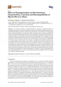
One potential approach for overcoming these limitations and boundaries is the ‘Simultaneous Emulsification and Mixing’ (SEM) process. This process is based on a modified disruption unit which combines the unit operations mixing and emulsification by inserting a micromixer shortly after the disruption unit [4,18,19]. This article will focus on the properties and possible applications of the SEM process, but will also introduce other approaches made in order to improve the conventional homogenization process. It will begin with providing some theoretical background of the topic (Chapter 2). Chapter 3 will focus on the improvements of the high-pressure process that have been developed in the last years including the SEM process. Some applications of the SEM process will be discussed in Chapter 4. Finally, Chapter 5 will provide a short summary and outlook. 2. Theoretical Background This chapter will give an introduction into the process of high-pressure homogenization (HPH). Furthermore, it will summarize the most important characteristics of mixing, since those are important for the operating principle of the SEM process discussed later on. 2.1. High-Pressure Homogenization Usually, HPH is conducted in two steps. First, a coarse emulsion is produced. Then the droplet sizes are reduced in a high-pressure homogenizer [15]. The idea of combining a high-pressure pump with a disruption unit in order to produce small-scale emulsions dates back to 1899 [20]. Piston pumps with pressure ranges between 20 and 4000 bar are most commonly used [3]. The high-pressure pump builds up energy that is then relaxed after the disruption unit and therefore leads to droplet disruption [16]. The energy input during droplet size reduction can be expressed as the energy density Ev that describes the average energy input per emulsion volume [21,22]. In case of high pressure homogenization processes, the energy density equals the pressure drop in the disruption unit. The obtained droplet diameter decreases with increasing pressure difference [21]—or increasing energy density—unless coalescence occurs [23]. The achievable droplet sizes also depend on the disruption unit as they influence the flow pattern which in turn determines droplet breakup. Disruption units can be divided by their flow guidance into radial diffusers, counterjet dispergators, and axial nozzle aggregates [2]. Typical representatives of these types are shown in Figure 1.
Processes 2016, 4, 46 Processes 2016, 4, 46
3 of 15 3 of 15
Figure 1. Disruption units in high-pressure homogenization. (1) radial-diffusers (reproduced with the Figure 1. Disruption units in high-pressure homogenization. (1) radial-diffusers (reproduced with permission from [3]; Behrs Verlag, 2012); (2) examples for counter-jet-dispergator: jet-dispergator the permission from [3]; Behrs Verlag, 2012); (2) examples for counter-jet-dispergator: jet-dispergator adapted from [24], Microfluidizer® adapted from [25]; (3) axial flow nozzle-system. adapted from [24], Microfluidizer® adapted from [25]; (3) axial flow nozzle-system.
Radial diffusers contain an axially mobile valve seat [21,26] which enables the variation of the Radial contain axiallyCounterjet mobile valve seat [21,26] whicha enables variation flow flow rate diffusers by varying the slitanwidth. dispergators include collisionthe area of two of or the more opposed jets of [16,21]. Both the counterjet dispergators axial rate by varying thethe slitemulsion width. Counterjet dispergators include a collision and area the of two or flow-nozzlemore opposed contain no movable parts which makes them suitable for very pressures [2]. Nozzle jetssystems of the emulsion [16,21]. Both the counterjet dispergators and the axial high flow-nozzle-systems contain can bewhich distinguished by their axial flow direction. Simple orifices usually aggregates consist of round noaggregates movable parts makes them suitable for very high pressures [2]. Nozzle can be holes of 0.1–2 mm diameter [10]. It has been reported that different disruption units lead to different distinguished by their axial flow direction. Simple orifices usually consist of round holes of 0.1–2 mm droplet[10]. sizesItwhen the reported same energy applied. For example, valvesdroplet are lesssizes energy diameter has been that density differentisdisruption units lead toflat different when efficient than orifices or the Microfluidizer geometries, esp. for oil in water (o/w)-emulsions the same energy density is applied. For example, flat valves are less energy efficient than orifices or the containing high viscosity oil [23,26]. Microfluidizer geometries, esp. for oil in water (o/w)-emulsions containing high viscosity oil [23,26]. Different mechanisms can cause droplet breakup: laminar shear or elongation stresses, turbulent Different mechanisms can cause droplet breakup: laminar shear or elongation stresses, turbulent stresses, and cavitation. According to recent reports, droplet breakup occurs after passing the stresses, and cavitation. According to recent reports, droplet breakup occurs after passing the disruption valve. In orifices, for example, the droplets are first elongated in the inlet area [10] and disruption valve. In orifices, for example, the droplets are first elongated in the inlet area [10] and then disrupted in the turbulent and cavitating flow in the discharge area [26,27]. On top of that, the then disrupted in the turbulent and cavitating flow in the discharge area [26,27]. On top of that, the components of the emulsions influence the flow regimes and thus the mechanisms predominantly components of the emulsions influence the flow regimes and thus the mechanisms predominantly responsible for droplet breakup [28–31]. Further information on droplet breakup can be found in our responsible for breakup [28–31]. Further information on droplet breakup can be found in our second paper droplet in this journal. second paper in this journal. 2.2. Mixing 2.2. Mixing Mixing is a unit operation of process engineering in which several substances, that differ in at Mixing is a unitare operation of process engineering in goal which several substances, that least one property, distributed in a defined volume. Its is to achieve homogeneity indiffer order in to at least one property, are distributed in a defined volume. Its goal is to achieve homogeneity in order improve product quality, chemical or biological conversions, or heat- and mass-transfer [32]. In to improve quality, chemical conversions, or heat-distributed and mass-transfer [32]. In theory, theory,product ideal mixing occurs whenorallbiological starting materials are equally instantly. In reality, ideal mixing occurs when all starting materials are equally distributed instantly. In reality, however, this rarely occurs, so that either the time needed for complete mixing (mixing time)however, or the this rarelyofoccurs, that either time the time needed for is complete (mixing of time) or the degree degree mixing so after a certain (mixing quality) used for mixing characterization the mixing quality of [18]. after a certain time (mixing quality) is used for characterization of the mixing quality [18]. mixing Macromixingisisthe therate-determining rate-determining step step in in most byby thethe largest Macromixing most mixing mixingprocesses processesand andisiscaused caused largest scales of motion in the fluid. On the other hand, mixing on the smallest scale of motion and the final scales of motion in the fluid. On the other hand, mixing on the smallest scale of motion and the final scales moleculardiffusivity diffusivityisiscalled calledmicromixing micromixing [33]. [33]. scales of of molecular Continuous mixers often in continuous processes andbecan be classified their Continuous mixers areare often usedused in continuous processes and can classified by theirbyresidence residence time, by their residence-time behavior, and by the way in which the mixing energy is time, by their residence-time behavior, and by the way in which the mixing energy is introduced.
Processes 2016, 4, 46
4 of 15
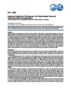
The required residence time and residence time behavior are influenced by process conditions, reaction kinetics (in case of biological or chemical reactions), and other factors [33]. Furthermore, the mixing energy can either be introduced by moving parts such as stirrers or it can be withdrawn directly from the flowing medium like in the jet mixer, for example [33,34]. The jet mixer can achieve rapid mixing in a short length of pipe mostly in turbulent flow regimes [33]. At least one component has to be added to the main stream with a considerably higher velocity than the main stream. The same working principle is used in the SEM process. 3. Developments in High-Pressure Homogenization Several ideas to improve the conventional HPH process have been investigated in the last years. These can be classified as follows: geometrical modifications of the disruption valve, inserting a second homogenization step, and including a micromixer in the disruption unit. It should be mentioned that in this paper, only systems based on the conventional HPH process containing a high-pressure pump and a disruption unit are discussed in detail. However, desired droplet size distributions could also be produced by alternative concepts such as jet homogenizer [35,36] or microfluidic systems [37]. Furthermore, this article will not go into detail on the possibilities of post-homogenization treatment, since these are already discussed in [38]. 3.1. Geometrical Modifications of the Disruption Valve Flat valves can be divided into three generations. While the first generation had a flat valve seat and stamp, the valve seat in the second generation was designed in a conical shape which induced extended elongation and reduced total pressure loss. The third generation flat valve is characterized by a wider valve diameter at a smaller homogenization gap [10]. Droplet disruption could be improved in the second and third flat valve generation while applying the same energy density or pressure loss compared to a first generation flat valve [15]. Stansted Fluid Power Ltd. (Stansted, UK) developed a modified flat valve made of ceramic material that enables much higher levels of pressure (3500 bar) than a conventional flat valve [6]. Both the conventional and the Stansted valve consist of a valve piston and a valve seat, but the flow directions through the valve are reversed. First, the fluid passes the mobile valve piston and is then accelerated by the narrow gap between the piston valve and the piston seat [39]. Although very high pressures could be realized, the achieved droplet sizes were limited due to coalescence. Modifications of orifices have been constructed in order to influence flow conditions and thus also to influence the mechanisms causing droplet breakup. Conical and circular inlets influence the elongation of the droplets, while conical outlets enhance the stabilization of the droplets while at the same time decreasing the pressure loss [27]. A modified orifice with two diagonal bores affects the intensity and distribution of turbulence after the homogenization unit. It has been shown that these orifices, also called two beam jet valves, result in smaller droplet sizes of an (o/w)-emulsion compared to conventional orifices [40]. The smallest droplet sizes were found at angles of 60◦ in relation to the direction of flow. A similar principle is used in the Y-chamber of the Microfluidics® (Westwood, MA, USA) disruption units [25]. Turbulence in the discharge area of the orifice can also be influenced by inserting an impact bead [41] or by using a redirecting valve [42,43]. These modified orifices are displayed in Figure 2. However, according to Aguilar et al. [28], the geometry of the orifice should be adapted to the material characteristics of the emulsion. The authors report that at low viscosity ratio between the disperse and the continuous phase, droplets are easily elongated but also tend to relax faster after elongation. Therefore, emulsions of low viscosity ratio require a fast build-up of turbulent flow, with the intensity of turbulence being more important for efficient droplet breakup than the time scales over which droplets are subjected to turbulent stresses. The opposite is true for emulsions of high viscosity ratios.
Processes 2016, 4, 46 Processes 2016, 4, 46
5 of 15 5 of 15
Figure 2. Modifications of orifices. (a) Concial orifice adapted from [27]; (b) Two beam jet valve
Figure 2. Modifications of orifices. (a) Concial orifice adapted from [27]; (b) Two beam jet valve adapted adapted from [44]; (c) Valve with impact bead adapted from [41]; (d) Redirecting valve adapted from from[43]. [44]; (c) Valve with impact bead adapted from [41]; (d) Redirecting valve adapted from [43].
3.2. 3.2. Inserting a Second Homogenization Inserting a Second HomogenizationStep Step In industrial homogenizers,aadouble double stage stage process in in order to increase the the In industrial homogenizers, processisisoften ofteninstalled installed order to increase emulsification efficiency of the HPH. Here, a second homogenization unit is inserted in line after theafter emulsification efficiency of the HPH. Here, a second homogenization unit is inserted in line first one. With regard to flow conditions, the second unit applies a back-pressure and thus influences the first one. With regard to flow conditions, the second unit applies a back-pressure and thus the pressure drop over first This has implications particularly for the for occurrence of influences the pressure dropthe over thedevice. first device. This has implications particularly the occurrence cavitation [45,46]. The ratio of back-pressure and inlet pressure is defined as a Thoma number (Th) of cavitation [45,46]. The ratio of back-pressure and inlet pressure is defined as a Thoma number [46,47]. It is reported that cavitation decreases with increasing Th and disappears at Thoma numbers (Th) [46,47]. It is reported that cavitation decreases with increasing Th and disappears at Thoma of 0.3 < Th < 0.5 [48]. The Thoma numbers that also influence droplet breakup and minimum droplet numbers of 0.3 < Th < 0.5 [48]. The Thoma numbers that also influence droplet breakup and minimum sizes were found at 0.15 < Th < 0.35 [48–50], depending on the high pressure unit and the emulsion droplet sizes were found at 0.15 < Th < 0.35 depending on the high pressure unit and the composition. Nevertheless, it was pointed out[48–50], that only the first homogenization unit is responsible emulsion composition. Nevertheless, it was pointed out that only the first homogenization unit is for droplet breakup. Therefore, the second homogenization unit can also be replaced by other process responsible for droplet breakup. Therefore, secondvalve homogenization unitvessel can also replaced units inducing back-pressure, such as atheneedle or a pressure [46].beIn dairy by other process units inducing a needle valve for or adeagglomerating pressure vesselfat [46]. In dairy homogenization, the secondback-pressure, homogenizationsuch unit as is also responsible globule aggregates that result from casein bridging in the first homogenizing step [10,51]. homogenization, the second homogenization unit is also responsible for deagglomerating fat globule Thethat tworesult homogenization can be two simple orifices or as modified valves. aggregates from caseinunits bridging inrealized the firstas homogenizing step [10,51]. Displacing the second homogenization canasintensify the turbulent in modified the discharge The two homogenization units canunit be axially realized two simple orificesflow or as valves. area of the first orifice [52]. Kolb et al. [5] stated that this new type of homogenization valve can Displacing the second homogenization unit axially can intensify the turbulent flow in the discharge reduce droplet sizes compared to a Microfluidizer or a flat valve due to reducing coalescence in the area of the first orifice [52]. Kolb et al. [5] stated that this new type of homogenization valve can reduce turbulent area between the two orifices. Karasch and Kulozik [53] proposed a double valve consisting droplet sizes compared to a Microfluidizer or a flat valve due to reducing coalescence in the turbulent of two beam jet valves for dairy homogenization.
area between the two orifices. Karasch and Kulozik [53] proposed a double valve consisting of two beam valves for dairy homogenization. 3.3.jetSimultaneous Emulsifying and Mixing The basic Emulsifying idea of the ‘Simultaneous 3.3. Simultaneous and Mixing Emulsification and Mixing’ process is to combine the unit
operations mixing and emulsification in order to create synergies between them [18]. It should be The basic idea of the ‘Simultaneous Emulsification andPost Mixing’ process is to combine the unit noted that the SEM process is also named ‘High Pressure Feeding’ (HPPF) process in some operations mixing and emulsification in order to create synergies between them [18]. It should publications [13,54,55]. Just as in the conventional process, a high-pressure pump is combined with be noted that the SEM process also named ‘High Pressure Post Feeding’ (HPPF) process some a disruption unit. The SEM is disruption unit however combines a simple homogenization orificein and a micromixer [4]. TwoJust streams the SEM disruption unita (Figure 3): one stream creates awith publications [13,54,55]. as inenter the conventional process, high-pressure pumpwhich is combined turbulent unit. jet andThe an additional mixing unit stream [18]. The first one, apassing valve or orifice, is often and a disruption SEM disruption however combines simplethe homogenization orifice called the ‘homogenization stream’ as it is responsible for setting up flow conditions responsible for a micromixer [4]. Two streams enter the SEM disruption unit (Figure 3): one stream which creates droplet or filament breakup. It is also often called ‘main stream’ as it is placed centrally even if a turbulent jet and an additional mixing stream [18]. The first one, passing the valve or orifice, isitsoften
called the ‘homogenization stream’ as it is responsible for setting up flow conditions responsible for
Processes 2016, 4, 46
6 of 15
Processes 2016, 4, 46 6 of 15 droplet or2016, filament Processes 4, 46 breakup. It is also often called ‘main stream’ as it is placed centrally even 6 ofif15its throughput may be lower than that of the ‘mixing stream’ or ‘side stream’. The desired synergies throughput may be lower than that of the ‘mixing stream’ or ‘side stream’. The desired synergies throughput may be lower than that of the ‘mixing stream’ or the ‘sidemixing stream’. The desired synergies between emulsification and mixing when stream is induced shortly between emulsification and mixingcan canonly onlybe beachieved achieved when the mixing stream is induced shortly between emulsification and mixing can only be achieved when the mixing stream is induced shortly afterafter the disruptive unit where the disruptive flow conditions are fully built up [4,17,56,57]. the disruptive unit where the disruptive flow conditions are fully built up [4,17,56,57]. after the disruptive unit where the disruptive flow conditions are fully built up [4,17,56,57].
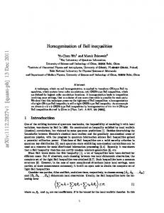
Figure 3. Function principle of SEM process. Figure 3. Function principle of SEM process. Figure 3. Function principle of SEM process. The emulsion morphology produced by SEM can be influenced by geometrical parameters as The as emulsion and morphology produced[4,18,56,57]. by SEM can be influenced by geometrical parameters well material parameters According to Köhler the SEMparameters process canasas The process emulsion morphology produced by SEM can be influenced by [18], geometrical wellwell as operated process and material parameters [4,18,56,57]. According toto Köhler [18], process can be in and seven different operational modes (Figure 4). The type of operational mode depends as process material parameters [4,18,56,57]. According Köhler [18],the theSEM SEM process canbe operated in seven different operational modes (Figure 4). The type of operational mode depends on whether pure phases or premixes are used and whether these phases are applied in the be operated in seven different operational modes (Figure 4). The type of operational mode dependson whether pure phases or premixes are used and these phasesthese are applied the applied homogenization homogenization mixing stream [17,18]. on whether pureor phases or premixes are whether used and whether phasesinare in the
or mixing stream [17,18]. homogenization or mixing stream [17,18].
Figure 4. Operational modes of SEM adapted from [19]. The different phases (continuous phase, premix, disperse phase) are displayed in different colors according to the axes.
Figure 4. Operational modes of SEM adapted from [19]. The different phases (continuous phase, Figure Operational modes of SEM from as [19]. The different phases (continuous phase, The4.operational modes SEM canadapted classified [18]: premix, disperse phase) areofdisplayed inbedifferent colorsfollows according to the axes. premix, disperse phase) are displayed in different colors according to the axes.
The operational modes of SEM can be classified as follows [18]: The operational modes of SEM can be classified as follows [18]:
Processes 2016, 4, 46
•
7 of 15
In the2016, operational Processes 4, 46
modes 2 and 6, pure phases are mixed in the micromixer. Primary7 droplets of 15 are produced due to the turbulent current after the orifice. These operational modes can also be • referred In theto operational modes 2primary and 6, pure phases are mixed in the micromixer. Primary droplets as simultaneous emulsification and mixing (SpEM). are produced due to the turbulent current after the orifice. These operational modes can also be • In the operational modes 1, 3, and 4, the already existing droplets of the premixes are disrupted referred to as simultaneous primary emulsification and mixing (SpEM). into smaller droplets. These operational modes can also be referred to as simultaneous • In the operational modes 1, 3, and 4, the already existing droplets of the premixes are disrupted homogenization and mixing (SHM). into smaller droplets. These operational modes can also be referred to as simultaneous • In the operational modes 5 and(SHM). 7, primary and secondary droplet breakup occurs since both pure homogenization and mixing disperse phase and emulsion premix are inserted into the homogenizer. • In the operational modes 5 and 7, primary and secondary droplet breakup occurs since both pure disperse phase and emulsion premix are inserted into the homogenizer.
The operational modes in which the disperse phase does not pass the orifice itself are based on modes in which the delivers disperse the phase does not conditions pass the orifice itself are on the ideaThe thatoperational the homogenization stream local flow required forbased emulsifying the idea that the homogenization stream delivers the local flow conditions required for emulsifying the disperse phase and mixing both streams [58]. the disperse phase and mixing both streams [58]. The operating principle of the SEM process can be realized using different disruption units. The operating principle of the SEM process can be realized using different disruption units. Figure 5 illustrates some of the SEM valves that have been presented in the literature. They can Figure 5 illustrates some of the SEM valves that have been presented in the literature. They can either either be simple orifices, modified orifices, or even double orifices. SEM flat valves have also been be simple orifices, modified orifices, or even double orifices. SEM flat valves have also been designed designed but of the recent was research was conducted with orifices. [18,59],[18,59], but most of most the recent research conducted with orifices.
Figure 5. SEM valves. (a) orifice SEM valve adapted from [4]; (b) double SEM valve adapted from
Figure 5. SEM valves. (a) orifice SEM valve adapted from [4]; (b) double SEM valve adapted from [58]; [58]; (c) SEM valve with modified inlet geometry adapted from [55]. (c) SEM valve with modified inlet geometry adapted from [55].
4. Applications of SEM Homogenization
4. Applications of SEM Homogenization
The SEM process has been tested in various application fields. This chapter will give an overview Thethe SEM process research. has been tested in various application fields. This chapter will give an overview over conducted
over the conducted research.
4.1. Preparation of Hybrid Nanoparticles
4.1. Preparation of Hybrid Nanoparticles Hybrid nanoparticles are of scientific and industrial interest as they can be used for several applications—e.g., paints are of high color intensity [60–62], electronic devices [63,64], and medical Hybrid nanoparticles of scientific and industrial interest as they can be used for several applications [65–67]. Hybrid nanoparticles can be prepared by miniemulsion polymerization a applications—e.g., paints of high color intensity [60–62], electronic devices [63,64], and in medical two-stage process [68–70]: first, a nanoparticle-in-monomer suspension is emulsified in a continuous applications [65–67]. Hybrid nanoparticles can be prepared by miniemulsion polymerization in phase and then the polymerization of the filled submicron-sized monomer droplets is conducted [55]. a two-stage process [68–70]: first, a nanoparticle-in-monomer suspension is emulsified in a continuous Hecht et al. consider high-pressure homogenizers to be the most suitable device to produce small phase and then the polymerization of the filled submicron-sized monomer droplets is conducted [55]. sizes for particle filled monomer droplets at a high throughput [55]. Figure 6 displays some Hecht et al. consider high-pressure homogenizers to be the most suitable device to produce small sizes nanostructured particles produced in dynamic high-pressure processes via miniemulsions [11]. for particle filled monomer droplets at a high throughput [55]. Figure 6 displays some nanostructured particles produced in dynamic high-pressure processes via miniemulsions [11].
Processes 2016, 4, 46
8 of 15
Processes 2016, 4, 46
8 of 15
In the thepast, past,ultrasonic ultrasonicsystems systems have been used to produce particle loaded droplets [71–73]. In have been used to produce particle loaded droplets [71–73]. Since Since nanoparticles can cause abrasion in homogenization valves [12], Hecht et al. used the SEM nanoparticles can cause abrasion in homogenization valves [12], Hecht et al. used the SEM process process for the miniemulsion polymerization especially with to regard to degree a high degree of nanoparticle for the miniemulsion polymerization especially with regard a high of nanoparticle filling filling (up to 60 wt %) [55]. As disruption unit, a simple orifice (Figure 5a) was used. To avoid abrasion (up to 60 wt %) [55]. As disruption unit, a simple orifice (Figure 5a) was used. To avoid abrasion of of the orifice, operational mode 1 (see Figure 4) was chosen: pure continuous phase was pumped the orifice, operational mode 1 (see Figure 4) was chosen: pure continuous phase was pumped through through the the orifice, orifice, while while the the premix premix emulsion emulsion containing containing the the nanoparticle-in-monomer-droplets nanoparticle-in-monomer-droplets was inserted as mixing stream. Droplets of the desired size range was inserted as mixing stream. Droplets of the desired size range (