state transition diagrams. This paper shows the derivation of the,USE transition diagrams based on perceived shortcomings of the "pure" state transition diagram ...
IEEE TRANSACTIONS ON SOFTWARE ENGINEERING, VOL. SE-ll, NO. 8, AUGUST 1985
699
Extending State Transition Diagrams for the Specification of Human- Computer Interaction ANTHONY I. WASSERMAN, MEMBER, IEEE
Abstract-User Software Engineering is a methodology for the specification and implementation of interactive information systems. An early step in the methodology is the creation of a formal executable description of the user interaction with the system, based on augmented state transition diagrams. This paper shows the derivation of the, USE transition diagrams based on perceived shortcomings of the "pure" state transition diagram approach. In this way, the features of the USE specification notation are gradually presented and illustrated. The paper shows both the graphical notation and the textual equivalent of the notation, and briefly describes the automated tools that support direct execution of the specification. This specification is easily encoded in a machine-processable form to create an executable form of the computer-human interaction.
odology, where users (or user surrogates) can provide useful information to help the development process. For example, the initial analysis phase includes not only traditional data and activity modeling, but also identification of user characteristics, e.g., ability to type, intensity of anticipated usage, motivation and education of users, etc. Attention is also given to the environment in which the system will be used, so that the system can fit in with the user's work pattern, and can be tailored to any constraints on terminal types or transmission
rates.
I. INTRODUCTION A N interactive system can be seen as having two components: the user interface to the system and the operations performed by the system. The user interface provides the user with a language for communicating with the system. The interface can take many forms, including multiple choice (menu selection), a command language, a database query language, or natural language-like input. In all cases, however, the normal action of the program is determined by user input, and the program may respond in a variety of ways, including results, requests for additional input, error messages, or assistance in the use of the system. The user interface is often the principal determinant of system success, especially for those interactive systems where usage (or purchase) is discretionary. Yet for many systems used on alphanumeric terminals, design of the user interface is often an afterthought, with the design based on systemoriented, rather than user-oriented, concerns. I
The second step of the USE methodology is external design, which involves design of the user interface(s) to the proposed system. The analysis step serves to identify major functions and required inputs and outputs, at least at a high level. The concern of external design is to determine how the user can request those functions and how the output will be displayed. Thus, instead of top-down or bottom-up design, the USE methodology uses an "outside-in" design. The third step is the creation of an executable version of the user interface defined at the previous stage, so that the user and developer can jointly explore, both objectively and subjectively, the usability of the original design, and to make modifications as needed. This-ability to rapidly create system prototypes, presenting the user view of the evolving system, is a key aspect of User Software Engineering. Clearly, there is iteration among the first three steps until one or more acceptable interfaces are found. In the remainder of this paper, we describe the notation used to specify this user interface in the USE methodology. We are not concerned here with the methodological process of defining the user interface, with the succeeding steps of the methodology that lead to a finished system, or with evaluation of the user interface.
attention is given to the nature of the user interface.
representatives).
Index Terms-Executable specifications, interactive information systems, rapid prototyping, software development methodology, transition diagrams, user interfaces, User Software Engineenng.
The User Software Engineering project was undertaken in II. USER INTERFACE DEFINITION WITH 1975 with the idea of combining concerns about user involveTRANSITION DIAGRAMS ment in the design of interactive information systems with In searching for an appropriate notation for describing user those of software engineering. The outcome of the effort is the creation of a methodology [1], [21 with a set of auto- interfaces to interactive systems, we established several remated tools to support the methodology [3]-(7]. User par- quirements, including the following: ticipation is very important at the early stages of the meth1) Fonnalism: The notation had to serve as a formal definition of the interface. Manuscript received February 8, 1984; revised February 20, 1985. 2) Completeness: The notation had to be self-contained, This work was supported by corporate research grants -from Nippon Electric Company and from Alcoa Foundation. including user input, system output, and linkage to system The author is with the Section of Medical Information Science, Uni- operations (application code). versity of California, San Francisco, CA 94143. 3) Comprehensibility: The notation had to be compreInterfaces for graphics-based systems and especially video games are based on the value of pictorial display and interaction. Therefore, more hensible both to system developers and to users (or their
0098-5589/85/0800-0699$01 .00
© 1985 IEEE
700
IEEE TRANSACTIONS ON SOFTWARE ENGINEERING, VOL. SE-11, NO. 8, AUGUST 1985
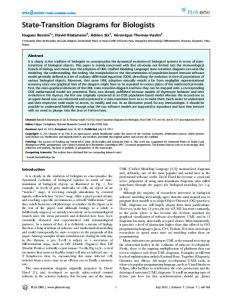
4) Flexibility: The notation had to accommodate a broad variety of dialog styles. In other words, the notation could not make assumptions about the nature of human-computer interaction, but had to give the designer of the dialog as wide a selection of possibilities as possible. This decision implies the need for a "low-level" approach to dialog specification. 5) Executability: The notation had to be directly executable to support prototyping, development, and testing of interactive information systems. We observed that the interactive system and its actions are driven by raw or transformed user input. Accordingly, an effective specification technique for programming languages can be used effectively for specifying user interfaces. One can write down the grammar of the user input, and associate program actions with the successful recognition of "words" or "phases" in the grammar. We decided to adapt transition diagrams for this purpose [8]. Transition diagrams have been used for a variety of language translators, including an early Cobol compiler (9], and are used as the formal specification of the MUMPS programming language [10]. (Transition diagrams have also been selected by others as an appropriate notation for specifying interactive programs [ 1] - [ 1 5] .) A transition diagram is a network of nodes and directed arcs. Each arc may contain a token, corresponding to a character string in the primitive alphabet (such as ASCII), or the name of another diagram. If the path is blank, it will be traversed as the default case, i.e., if all other paths leaving a given node fail. Scanning of the diagram begins at a designated entry point and proceeds until reaching an exit node or a dead end (no successful match on the paths from a given node). An operation may be associated with any path; traversal of the path causes the associated operation to occur. Intuitively, one can see that paths may contain arbitrary strings and that the state transitions can invoke arbitrary operations. The distinguished inputs then lead to different states from which other input symbols may cause yet additional actions. We began by using a simple transition diagram model to design and build several small interactive systems. This model contained just three different symbols, as follows: 1) node-shown by a circle, representing a stable state awaiting some user input. Each node within a diagram has a unique name, and an output message may be displayed when a node is reached. One node is designated the starting node, designated by two concentric circles, and there is a single exit point. 2) arc-shown by an arrow, connecting nodes to one another. Each arc represents a state transition based on some input. The input is designated either by a string literal, such as "quit," or by the name of another diagram, enclosed within angle brackets, such as . One arc emanating from each node may be left blank, in which case it becomes the default transition, and is taken only when the input fails to match that specified on any of the other arcs. We shall assume for the moment that there is no ambiguity concerning which arc to take for a given input at a given node. 3) operation-shown by a small square with an associated integer. An action may be associated with a transition to represent an operation that is to be performed whenever a spe-
'q' node START
Q T
RAPID/USE Tutorial Example Program', Please choose: ', a- Case a', b - Case b', ?-
Help',
q - Quit',, Your choice:
node HELP
'Valid commands are " a" and "b"', 'Press any key to continue'
node CASEA
'You are at CASEA',' 'Press any key to continue'
node CASEB
'You are at CASEB', 'Press any key to continue'
node ERR
'Sorry, but you made an error 'Press any key to continue'
-
please try again.',
node QUIT 'Thank you -- good bye' Fig. 1. A USE transition diagram.
cific arc is traversed. The same action may be associated with more than one arc. A very simple diagram is shown in Fig. 1. The diagram begins at START, where it waits for input. Input is a string terminated by a carriage return. There is a transition to one of five nodes based upon the input. The input of "a" causes action 1 to be performed during the transition to CASEA; the input of "b" causes action 2 to be performed during the transition to CASEB, the input of "?" causes a transition to HELP, and the input of "q" causes a transition to QUIT; anything other than "a", "b", "q", or "?" causes a transition to ERR. The text beneath Fig. 1 shows the message displayed when a transition is made to that node. Thus, this figure is a very simple instance of a menu-selection dialog, with the START
701
WASSERMAN: SPECIFICATION OF HUMAN-COMPUTER INTERACTION
node used to present a menu, and the five other nodes representing two system commands, a quit command, a help command, and an error case. We quickly recognized some significant shortcomings with this simple model, including the following. 1) Output Specification: It was important to specify formatting and layout of system output, rather than just describing the message itself. 2) Display of Input Information: It was not possible to include as part of an output specification any text that had been recognized as input from the user. Yet such display is a major component of many interactive programs. 3) Input Processing: Some interactive dialogs accept a line of user input, followed by a terminator, such as a carriage return, before performing an operation or making a transition, while others respond on a single key stroke or the recognition of a specific key, such as a function key. The simple model we were using accepted only a variable length string, followed by a carriage return. 4) Diagram Complexity: Complex dialogs result in very complex diagrams, greatly reducing their comprehensibility and increasing the likelihood of errors in drawing or maintaining the diagrams. 5) Alternative Displays Based on Operations: The logical flow of an interactive program is often dependent upon the result of an operation, e.g., success or failure in a table lookup. Such a situation could not be represented with the simple transition diagram model. 6) Time Limits: It was not possible to make a transition after a fixed amount of time as needed to produce a remainder message. We therefore sought to develop a transition diagram-like notation that would overcome these shortcomings. We also wanted to define a textual representation of these diagrams to facilitate their encoding for creating an executable version of the user interface. We shall henceforth refer to these diagrams as USE transition diagrams. We now take up the approaches to these shortcomings that were introduced in USE transition diagrams. III. OUTPUT SPECIFICATION A node is used to display a message. In its simplest form, a message may simply be a text string, such as shown in Fig. 1. In practice, though, more power is needed for output
We adopt the convention that the upper left hand corner of the screen is (0, 0) and the last row and column are each designated by "$". Thus, a message to be written at the beginning of the last line could be addressed with r$, cO. A relative movement is designated with "+" and "- ," so that one could write r + 2, c25, 'Your request...'
In many cases, a message may contain an entire screen full of information, so that the message could contain an arbitrary mixture of text and positioning directives. One could write, then,
cs, r5, c5, 'Please choose one of the following:', r + 2, cdO, '1) deposit', r + 2, cdO, '2) withdraw', r + 2, cdO, '3) help', r + 2, cdO, '4) quit', r$, rv, 'Your choice...', sv
to specify a screen filled with text. Note that screen-oriented directives are used in this example. cs rv sv
clear screen and go to home position (rO, cO) use reverse video (if available) return to standard video
Additional screen-oriented directives provide needed cursor control. In all cases, these directives may be included in an output specification. hm go to home position (0, 0) nl start a new line (r + 1, cO), cl clear to end of line on current row ce clear to end of screen from current line dc delete the character at the current position, then shift subsequent characters on line to left dl delete entire line (current row) and scroll lower lines (if any) upward is 'text' insert the text beginning at the current position il open a blank line at the current position and move lower lines down
B. Reuse of Messages Second, we may want to reuse a message. Common examples of this situation are error messages, screen headings, and online assistance. The structure of a message is identical to that of a node specification, so that a message may include cursor movement information, text strings, and variable names. We define a message name, then refer to it by that name whenever we want to display that message. Conceptually, we would define
specification. A. Cursor Control First, it is useful to take advantage of screen-oriented displays, specifying the exact or relative position on a screen at which a message should be placed. Thus, one might want to specify that the message begin on row 12 at column 25, or that it begin two lines below the previously written message. message prompt We can specify the message as r$, rv, 'Your choice...', sv r12, c25, 'Good morning, fearless leader' and we then write It is often desirable to center a message on a line. Rather than counting spaces to find the correct starting point, the symcs, r5, c5, 'Please choose one of the following:', r + 2, cO, '1) deposit', bol "c_" may be used to denote the center, so that the r + 2, cO, '2) withdraw', specification r + 2, cdO, '3) help', rl2, c_'Good morning, fearless leader' r + 2, cO, '4) quit', would cause the message to be centered on line 12. prompt
702
IEEE TRANSACTIONS ON SOFTWARE ENGINEERING, VOL. SE-11, NO. 8, AUGUST 1985
The appearance of the message name "prompt" causes the subThis screen partitioning is a first step toward the multiple stitution of the text associated with the message definition of window interfaces employed in systems such as Smalltalk-80 "prompt." and Interlisp [16], [171. We return to this point later.
C. Tab Settings The layout of the previous example is dependent upon the alignment of four lines of text, requiring the inclusion of the directive "clO" in four different places. Changing the placement of these lines requires changing four occurrences of the column directive in this message, and potentially other dependent column directives in other messages that might be concurrently displayed. Flexibility and the ability to modify layouts rapidly suggests the need to associate tabs with column settings. We introduce the tab definition and allow a column to be associated with a specific tab declaration, as follows. tab t_0 5 tabt_1 10 cs, r5, t_O, 'Please choose one of the following:', r + 2, t_ 1, ') deposit', r + 2, t_ 1 '2) withdraw', r + 2, t_1, '3) help', r + 2, t_1, '4) quit', prompt
In this way, the alignment may be changed with only one change to the definition, namely the column associated with the tab definition.
D. Partitioned Screens Another problem in controlling a display is to be able to partition the screen into two or more parts and to move freely between them. For example, we may wish to use the bottom two lines of the screen for error messages, regardless of what has been placed on the remainder of the screen. In that case, we would like to "mark" a position on the screen, move to another position, and then return to the marked position. The directives "mark" and "tomark" provide part of this capability. The upper and lower case letters may be used as names of marks and then referenced. Named marks may be included as part of the output specification. The nodes node one r + 1, 'Your reply: ', mark_A node error tomark_A, cl, r$, mark_E, rv, 'Please type a number from 1 to 5', sv, tomark_A allow an erroneous reply to be cleared, and an error message to be displayed on the bottom line (in reverse video), after which the cursor returns to the point at which the reply is wanted. Note also that mark_E is set to the beginning of the error line so that some other node could be defined node clean_err mark_B, tomark_E, cl, tomark_B to remove the error message at a subsequent point. The removal should not be done in node one, since it would disappear from the screen before the user had- a chance to read it.
IV. VARIABLES IN DIAGRAM SPECIFICATION Output messages are often dependent upon previous input or upon computed results. Data entry systems must display and/or reformat information input by a user, as well as passing that data to operations. Programs involving multiple screens typically redisplay data given on one screen on a subsequent display. For example, a bank teller program may obtain account information, and then display the account holder's name or account number later in the interactive dialog. Thus, the limitation of fixed text in the output specification is inadequate, and we must introduce variables. We adopt the convention that a variable may be assigned the string received on a specific input, or be assigned a value as the result of an action. The variable name is shown on one or more arcs in a diagram. When such an arc is traversed, the input string is assigned to that variable. Thus, the appearance of a variable name on an arc emanating from a node means that the input is assigned to that variable. If there were a message such as cs, rIO, cdO, 'Please type your name:'
the resulting input could be assigned to a variable called "name," and could subsequently be displayed as follows: rO, c40, 'User--', name
within a node or another message. As with variables in programming languages, we wish to define constraints on their values. We define four kinds of constraints: 1) data type: string, integer, float, scalar, date, time 2) string length: minimum and maximum length (both
optional) 3) range of values: lexicographic or numeric ranges, depending on type (both optional) 4) display format: used as default format for displaying values of the variable. Thus, all of the following are variable definitions: string name string licenseplate [1:7] string longstring [50: *] string a to c word range 'a'..'c' integer count integer testresult [2:2] range 30..50 scalar weekday (monday, tuesday, wednesday, thursday,
friday) float flt display ("r7.2") date sunbday init '19820222 time lunch init @123000 The numbers in square brackets delimit the length of the input in characters. The range constraint specifies a restriction on the value of the variable, where the range for "integer" is given by integer values and the range for "string" is given by the ASCII collating sequence. An asterisk "*" may be used to denote the absence of a fixed limit. The syntax for the
WASSERMAN: SPECIFICATION OF HUMAN-COMPUTER INTERACTION
display format is similar to that used for the printf function in the UnixTM standari I/O library, and has been extended to support the display of scalars, month (numeric and text), day, year, weekday, hours, minutes, and seconds, as well as left, right, and center adjustment of displayed variables. Variables may be assigned by appearing on a transition, so
input meeting the constraint(s), if any, causes the transition and makes the assignment. In Fig. 2, the transition from step I to step 2 causes the variable "restname" to be assigned the user input string. Once a variable has been assigned a value, it may subsequently be used in messages and in, actions. As with variables in other programming notations, it may also be assigned a new value, that
user
703
stepi
restname
step2
Fig. 2. Assignment to a variable.
proach is commonly found in multiple-choice (menu selection) applications, not only with keyboard input, but also with touch screens and mouse input. Indeed, single keystroke (or equivalent) processing is a key aspect of many highly interactive systems. Rather than buffering the input, it must be
processed immediately. Thus, the two forms of input processing must be distinguished, which canpot be done with the simple model of transition diagrams. We introduce the "'" symbol to denote this immediate transition, which we term a single key transition. The V. INPUT PROCESSING appearance of the "!" followed by a character on an arc means The basic transition diagram model assu-mes that the input that a single . "character" input is used to cause a transition. to determine transitions along an arc is a variable length string Fig. 3 gives an example of this case. terminated by a carriage return. Also, there must be some input to cause a transition. All of these assumptions are un- B. Specific Character Recognition similar necessarily restrictive, in addition to being unrealistic for the A Asmlrproblem arises when it is desired to make a tranpractical design of interactive systems. Therefore, extensilons sition based on the recognition of a particular character, whento the transition diagram model are needed for these cases. ever it appears in the user input. This is termed a special key First, though, we observe that the input character set must transition, and is shown by preceding the key with an amperbe extended beyond the typical set of 95 ASCII printable sand ("&") on the arc. The ampersand indicates the immegraphics, to accommodate. control characters, function keys, diate transition, without waiting for a terminator, rather than and other inputs that may be received from a modern terminal accepting input until-a terminator is received. keyboard. We use the following symbols to represent the ex- Note that "single key" and "special key" transitions are tended input character set. difficult. In a command-oriented system, it may be possible to interrupt a command or any other input by typing a speesc escape cific key, such as control-C or "?". It is only the "special key" cr carriage return (default) concept that permits this interruption, unless all input is hanbs backspace dled as "single key." line feed lf We have also considered the case in which a specific key, del delete such as an escape or a function key, can be globally used to tab tab character (ctl_i) ctl_{A-Za-z} any control character, such as ctl__D for any terminate a diagram and perhaps return to a specific node in a specific diagram. From a notational standpoint, it is necesletter function keys fO through f9 f {0-9} sary to have an explicit arc from every node where such an input could be received. (It is straightforward to implement t up arrow 4, this idea in software, though.) Without such an explicit arc, down arrow a diagram (or, as we shall see, a set of diagrams) may have left arrow unconstrained flow of control (the goto problem); furtherarrow -+ right such home home key branching in a set of diagrams raises traditional more, programming language questions about the scope of variables. Thus, in the same way that one can write a string literal on an arc, one can write any of these symbols, treating them as C. Truncating Input String Length TThe dde fault ccase in transition "reversed words" and prohibiting the use of variables with diagrams iS to accept a string these names. of any length until a carriage return is received. We wish first
-nput
to consider strings of fixed length (frequently length 1), and A. Buffered versus Unbuffered Input also strings terminated by $omething other than a carriage reAs noted, the assumption of inputs terminated by carriage turn. Consider the very common case of asking a user for a returns is very restrictive, and fails to represent many of the "yes" or "no" response. The decision can normally be made most common uses of interactive systems. While we use that by examining the first character of the user input, so that a assumption as a default, we need mechanisms for overriding variety of different response can be handled similarly. Even tmat case. in this simple case, the truncation greatly simplifies the probFirst, a single keystroke may be used to determine the ap- lem of decoding input, which might be any of"N," "n," "NO," propriate branch, without a terminating character. This ap- "No, or "no, excluding numerous possibilities from languages other than English. Note that the length option is different from the single key option in that the trunTMUixis a trademark of AT&T Bell Laboratories.
length
704
IEEE TRANSACTIONS ON SOFTWARE ENGINEERING, VOL. SE-1 1, NO. 8, AUGUST 1985
Fig. 3. Transition diagram illustrating immediate transition.
cation is only applied after the input termination character (normally the carriage return) is received.
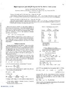
D. Nonstandard Terminators The carriage return default may be overridden with the until option. In the vi text editor for the Unix operating system, for example, insertion mode is terminated with the "escape" character. In other applications where the input may extend over several lines, the carriage return must be treated as a normal input character, with the terminator switched to a different character. Thus, one might wish to describe that all input received prior to an escape character will be assigned to a variable named inputstr. The until feature may be combined with the length feature, so that an input string may be truncated to a fixed length regardless of the terminator. Fig. 4 illustrates the notation used in the USE transition diagram for nonstandard terminators and/or fixed length strings. This information precedes the input string(s) and is denoted by the slash symbol 'l'.; A list of zero or more alternative terminators is given to the left of the "/" and the length, if fixed, is given to the right. The fragment of the diagram shown in Fig. 4 indicates that input is read until an escape or a tab character is received, and then truncated to eight characters. The resulting string is assigned to variable instring. These extensions to input processing, the extended character set, single key input, special key transitions, alternate terminators, and input string truncation, allow the description of a much greater set of interactive dialogs than was previously possible. VI. DIAGRAM DECOMPOSITION The added expressiveness given by the output specification notation, the inclusion of variables, and the extensions to input processing made it possible to describe most interactive systems using alphanumeric display terminals. The USE transition diagrams could be used with a means for specifying the actions, and thereby serve as a specification method. One important aspect of specifications, though, is comprehensibility. We found that it was very easy to create large complex diagrams that could not easily be written or understood. Diagram complexity arose initially from the desire to provide error handling and help facilities in the interactive dialog. By following our own guidelines for designing inter-
star
esc,tab/8
comman
getarg
Fig. 4. Nonstandard terminators in USE transition diagrams.
active systems [181, we were led to provide a help arc and an error arc from each node where user input could occur (virtually all). Accordingly, the number of nodes and arcs proliferated. The situation was even worse if one wanted to provide a different message on the second occurrence of an error than on the first. At first, we simply adopted the strategy of drawing a set of diagrams with no error handling and no interactive help facilities so that the diagram presented the "normal" flow of dialog. Yet this was also inadequate as we attempted to model increasingly complex dialogs and systems.
A. Subconversations The solution taken was to introduce a hierarchy of diagrams, so that any diagram could "invoke" another diagram. A connected set of nodes could be named, and could be "called" from another diagram. This idea of a "subconversation" was useful because it also modeled a commonly occurring situation in interactive systems: a set of "transaction types." Accordingly, a fourth symbol was added to the node, arc, and action: 4) subconversation-shown by a rectangular box, with an associated diagram name. When an arc enters a subconversation"box, traversal of that diagram is suspended, and control is transferred to the starting node of the diagram named in the subconversation box. The new diagram is then traversed until its exit point is reached, at which point control returns to the "calling" diagram, and the subconversation box is exited. A simple example of this situation is shown by the diagram structure of Fig. 5, where there are subconversations for "deposit," "withdraw," and "balance." The capability for any node to have multiple exits is retained in the subconversation by permitting a diagram to return a value to the invoking diagram so that the branch upon exit from the subconversation may be determined by the return value. The returned value is denoted by a nonnegative integer preceded by the "#" symbol in the invoked diagram. If more than one arc emanates from a subconversation box, the associated return value used to determine the branch can appear on each arc. We adopt
WASSERMAN: SPECIFICATION OF HUMAN-COMPUTER INTERACTION
705; 'yes'
#1
query
exit
#)4
no'
Fig. 6. Returning values from subconversations.
quit
Fig. 5. The use of subconversations for transactions.
the convention that such values may only be returned to the immediate caller, i.e., one level of invocation. This use is shown in Fig. 6. B. Transitions Described by Diagrams Until now, we have assumed that all inputs are described either by a string literal (a directly named sequence of characters) or by an input string that is immediately assigned to a variable. In some cases, though, it is useful to use a diagram to describe the syntax that causes a transition. Rather than using a string literal or a variable name on an arc, one can use the name of a diagram. That diagram, and any additional levels invoked from that diagram, must be successfully traversed to cause the given arc to be traversed. This situation is shown in Fig. 7; in Fig. 7(a), the diagram name is associated with an arc connecting nodes."one" and "two," while Fig. 7(b) 'shows the diagram xtoz. 'Note that is another possibility for the traversal from "one" to "two, which can also be tried. This use of subconversations allows recognition of a string composed of several components, possibly of indeterminate length, without overly complicating the higher level diagram. As before, the called diagram could be inserted into the higher level diagram, without altering the effect. In this case, though, it becomes possible to hide the structure of the recognized string. This construct is also useful for allowing several dif'ferent strings to cause the same transition, which is frequently needed for' dialogs supporting novice and expert interfaces,
for example.
C. Decomposing Messages and Actions Another important option is the ability to decompose messages and/or actions. Suppose that we want to perform action 2 on one arc, actions 2 and 3 in response to another input, and actions 1 and 2 in response to yet another input. To do so, one must create an intermediate node to permit the actions to be specified independently. Yet we do not want to require additional input to cause the second action to occur. Simi-
(a)
((start )
x
z
en
(b) Fig. 7. (a) Using diagram names for arc traversaL (b) Use of a subconversation for string recognition.
larly, one may wish to display two separate messages in response to a single input without waiting for additional input from the user. In both of these cases, one must make an automatic transition from one node to another. This case, called the skip case, is denoted by a "+" on an arc; of course, no string, return value, or diagram name can appear on such an arc. D. User Interfaces as a Hierarchy of USE Transition Diagrams The use of subconversations is both an aid to diagram decomposition and a notational convenience. There are, however, several distinct advantages to their use. 1) Any diagram may be referenced from other diagrams in a dialog and thereby reused; this supports the creation of libraries of diagrams that can be integrated into systems. 2); A higher level diagram can often be designed without making decisions about the actual input text; this approach allows decisions about the dialog to be deferred and isolated, and therefore changed easily. 3) Subconversations help to break up a diagram that has a large number of nodes; to aid comprehension, diagrams should contain fewer than 10 nodes. 4) Subconversations help to illustrate the structure of a dialog; many dialogs are naturally hierarchical and the subconversation mechanism allows this hierarchy to be shown in the diagrams.
706
IEEE TRANSACTIONS ON SOFTWARE ENGINEERING, VOL. SE-11, NO. 8, AUGUST 1985
VIII. SEMANTIC ASPECTS OF USE TRANSITION DIAGRAMS Until now, transitions between nodes in diagrams have been driven by the syntax of the user input. The extensions have either been structural, e.g., subconversations, or directed to finer input control,'e.g., unbuffered input. Even the introduction of variables into diagrams did not alter this situation. However, it now becomes necessary to introduce semantic dependencies into USE transition diagrams.
A. Returning Values framr Actions We previously noted that the direction of a dialog is often dependent upon the result of an action. For example, in a banking system, the user (a teller) would be asked to input a customer account number. A subsequent action would be to look up this account number in the bank's customer account database. The next message presented to the teller would depend on the success of the search. To achieve this effect, it is necessary to associate a return value with the action, and then to branch on that value. This is easily accomplished in our notation by indicating one or more arcs emerging from an action box, with arcs labeled with alternate return values, following the same approach used for subconversations. This situation is shown in Fig. 8. One path, labeled 1, leads to node found, while the other path, labeled 2, leads to node notfound. Note that the continuation from an action may be either unconditional, as we have previously seen, or conditional based on a return value. In the unconditional case, there may be a returned value, but it will not affect the transition following the action.
ge(acct
acctno
4
2
notfound
Fig. 8. Branch determined by value returned from action rules.
omitting the description of the actions on which they operate. The data dictionary is represented by a set of relations, specified in the Troll/USE data definition and manipulation language, and shown in Fig. 9 [5], [20]. The first diagram, the main diagram for the data dictionary system, is shown in Fig. 10(a). Three features are worth not-
ing in this diagram. 1) The action box numbered "2" is a call to the database script "startup." If this action succeeds (return "ok"), then control flows, to node "start;" otherwise, control flows to "riodb" and "x"' and the program terminates. 2) The center of activity is node "select," which provides a menu-like interface to the user, providing the user with the ability to enter the subconversations "add," "modify," "delete," and "query." The "select" node also provides for terminating the program, asking for help, and handling unexpected input (the "error" node). 3) The structure found in this diagram is generic for'transaction-oriented interactive programs. Many interactive information systems exhibit the same structure, and this diagram B. Time Limits can be e,asily modified to suit other applications. (Note the diatransition In modeling interactive systems with state to Fig. 5.) similarity since time, express to way we no convenient found grams, transitions are linked to user input. In practice, though, one often expects user input within a fixed amount of time, with an unexpected delay indicating a problem. Thus, it is desirable to be able to effect a transition on the expiration of a predefined time limit. In this way, it is possible to branch to another node, from which a reminder or help message can be
displayed. We thus introduce the alarm transition, and denote that transition by writing the time limit on the appropnate arc, e.g., 30". The alarm transition is made if no input is received from the user before the time limit expires.
The subconversation "add" is shown in Fig. 10(b), and has much the same structure as does the top-level diagram, asking the user to specify the type of entry to be placed in the data dictionary. (Clearly, this 'dialog has been designed to minimize typing and to present a screen-oriented interface to the
user.)
Note that the subconversations "add_element" through "add_message" all'return the value 0 if the item is successfully inserted in the data dictionary. This return value is used to direct control flow to node "inserted," which displays the message "successful insertion" before prompting the user for another entry. The "add" subconversation then invokes "add_process" when the user wisheq to define a new process and store information about that process in the data dictionary. Several aspects of the diagram shown in Fig. 10(c) are worth noting. 1) Three different kinds of actions are performed in this diagram. The actions "checkpro," "inspro," and "delparams" operate on the database shown in Fig. 9, as indicated by the use of the "'call" to the actions. The action "CallEdit" is to an executable program, to be written in a high level programming language; it is, in fact, a call to the vi editor for a file to
VIII. AN EXTENDED EXAMPLE To this point, all of the examples of the USE transition diagram specification method have dealt with "toy" examples, intended to denote the overall style and scope of the specification method. In this section, we show a small part of a much larger example, a data dictionary system to support a variant of Structured Systems Analysis [191. This example not only shows a broad range of the features of the USE specification method for interactive systems, but represents a running application system in everyday use. Because of space limitations, though, only three of the 31 diagrams representing hold the process' description for the given process. Finally, the system are shown, and the display is limited to the dia- there is a case statement, denoted by the "cs" action box, grams themselves (with the associated'text and action calls), which controls branching after the "checkpro" action is per-
WASSERMAN: SPECIFICATION OF HUMAN-COMPUTER INTERACTION relation data-element [key name] of name: string; eLdescripl,eLdescrip2,el-descript3,el-descrip4,el descrip5: string; eLtype: string; eLconstraints: string; eLnotes: string; eLcount: integer; end; relation data-store [key name] of name: string; store-notes: string; store-count: string; end; relation data_flow [key name] of name: string; flow-notes: string; flow-count: integer; end; relation process [key name] of name: string; proc_module: string; proc_notes: string; end; relation proc_params [key name, paramname[ of name: string; paranLname: string;
paramttype: scalar(inparam,outparam);
end; relation message [key name] of name: string; msg_descript: string; msg_number: integer; end; relation allnames [key name] of name: string; name-type: scalar (element,store,flow,proc,msg); end; relation flow-parts [key name, component] of name, component: string; end; relation store-parts [key name, component] of name, component: string; end;
Fig. 9. Relational database schema for data dictionary.
formed. The USE transition diagram notation does not allow two consecutive action boxes, so it is necessary to interect the dummy node "hackl" between the call to "checkpro" and the case statement. 2) Three different values may be returned to "add," representing successful insertion of the information (0), an error in insertion (1), or user cancellation of the insertion (2). Referring back to Fig. 10(b), we note that the "add" diagram does not presently distinguish between the latter two cases. 3) The arc "skip" feature, denoted by "+", is used several times, when actions and/or displays are performed without intervening user input. Without the skip feature, it would be necessary to combine information that is logically separate or to require user input in the interim. 4) The message "main.lastline" is used, allowing the dialog designer to defime some standard message formats in the main diagram and then use them throughout the dialog. This feature improves consistency of the interface design for the user.
IX. EXECUTABLE SPECIFICATIONS As described in the introduction, a critical step in applying the User Software Engineering methodology is to create an executable version of the user interface. To this end, we have designed and built a system called RAPID/USE, which consists
707
of two components: the transition diagram intepreter (TDI) and the action linker [31, [211. The TDI was designed to accept an encoding of the USE transition diagrams that resembles the diagrams and messages as much as possible.2 This encoding, called a dialog description or a script, is transformed into tables by TDI. In this way, one can draw the diagrams and quickly transform them to an executable form. The encoding may be achieved either by editing the textual representation of the diagrams, or by using a graphical tool, the transition diagram editor [22], to draw the USE transition diagrams interactively, and to have the TDI dialog description generated automatically. Input to TDI consists of one or more diagram descriptions, each representing a transition diagram. Each diagram may have five types of statements. 1) Diagram name statement-identifies the diagram, its entry node and exit node. 2) Variable definition statements-permit the use of names to describe strings of alphanumeric or numeric characters, along with range constraints on their values. 3) Message definition statements-permit the use of names to describe messages that are to be called from multiple points in the diagram. 4) Node definition statements-define the node names for the diagram, along with the associated messages and screen control for each node. 5) Arc statements-describe the structure of the diagram and its transition conditions. The Action Linker part of RAPID/USE allows programmed actions to be associated with the transitions. Routines may be written in C, Fortran 77, or Pascal. (Linkage to other languages can also be provided.) The syntax for the nodes is virtually identical to that shown in Fig. 10(a)-(c). The description for the arcs is given by the name of the starting node, followed by all of the possible branches and actions emanating from that node. Fig. 11 shows the TDI text for the diagram shown in Fig. 10(a). An inspection of this text will show that it is a direct encoding of the diagram itself. This encoding is done automatically by the transition diagram editor, and may also be done manually by someone without access to the graphical editor. Thus, RAPID/USE is used both for building and validating user interfaces (TDI) and for building functioning systems (TDI+ Action Linker). X. FURTHER EXTENSIONS TO DIALOG SPECIFICATIONS The USE transition diagrams, as described so far, cover a very broad range of the interactive dialogs that are suitable for user interfaces on "intelligent" alphanumeric display terminals. Furthermore, both the diagrams and the accompanying TDI notation are independent of the physical characteristics of any specific terminal. Thus, these diagrams may serve as a general descriptive technique for interactive systems. With recent advances in computer terminals and worksta2 Thepresent distribution of RAPID/USE supports all of the transition diagram features described in Sections III-VII except for some restrictions on transitions described by diagrams (Section VI-B).
78IEEE TRANSACTIONS ON SOFTWARE ENGINEERING, VOL. SE-l1, NO. 8, AUGUST 1985
708
main error
help
'belp','?'
(seu
ok
+2
+
se
fail
3
Actions 1 2
call shutdown call startup
diagram main entry setup exit x database 'usedddb' library '../scripts'
tab t_Q 15 tab t_1 20 message header
cs,r2,cO,c_'USE Data Dictionary'
message lastline r$,cO,'Hit any character to continue.'
node setup node select
tomark-A,ce,r-I3,tLO,'Please choose ', r+2,tJ,I'1: Add a dictionary entry.', r+2,t i,'2: Modify a dictionary entry.', r+2,t_L,'3: Delete a dictionary entry.', r+2,t1-,'4: Query data dictionary',
r+2,t.l,'help: Information on use of program', r+2,t_i,'quit: Exit USE/Data Dictionary',
r+2,t.0,'Your choice:'
node help
cs,r$-3,cO,'For more information about a command, enter', r$-2,cO,'the command number, press return and then type "help" or"?" r$ ,cO,'Hit any key to continue'
node nodb
cs,r$,cO,'Could not open database directory'
node start
header,markA
node x Cs
node errorl
r$-1,cO,rv,bell,/Please type a number from 1 to 4.',sv, lastline
(a) Fig. 10. (a) Top-level USE transition diagram of data dictionary system.
WASSERMAN: SPECIFICATION OF HUMAN-COMPUTER INTERACTION
709
add
O*dtelement>
help
dtstore>
'h p' ?'
'3'
n'd_flow> ck3ddtprocess>
ero2
in
.( diagram add entry select exit x
tab t_O 10 tab t_l 15 node errorl
r$ ,cO,rv,'Please type " y" or "n" ',sv,tomark_E
node select main.header,
r4,cO,c_'Add entry to dictionary', r+2,tCO,'Please select type of data entry: ', r+l,tCl,'1: data element', r+l,t_I,'2: data store', r+l,tCl,'3: data flow', r+l,t_l,'4: process', r+l,t_l,'5: message',
r+2,tCO,'Your choice (1-5):
node help
cs,rO,cO,c-'USE/Data Dictionary', rl2,cO,c_'Add new entry', main.lastline
node x
node inserted
r$-4,cO,'Successful insertion'
node error2
rS-1,cs,rv,bell,'Please r
type a number from n1" to "5" ',sv,
,cO,'Hit any character to continue.'
node noinsert
r+2,cO,'Another entry (y/n)? ', mark.E
(b) Fig. 10. (Continued) (b) The "add" subconversion of data dictionary system.
IEEE TRANSACTIONS ON SOFTWARE ENGINEERING, VOL. SE-11, NO. 8, AUGUST 1985
710
add-process nm nename T
ca
hCk I
( 9 ) 7 0 1~ ~ ~ ~ ~ ~ zcaaa
~ ~ ~ ~~~~~1+ e
-u'help','!'p-
50'
'help','?'
notes
Actions 1 2 3 4 5
call checkpro(newname->dups) case dups call inspro(newname,newnotes) call delparams(newname) do CallEdit(" vi %s.pdl", newname)
help.noteu
newnotes
cofirm
no','n'
"' +;.y 3
diagram add-process entry start exit x
digit dups alpha newname
f
ok
alpha newnotes ( error2
@-h
x
node start main.header,r+2;cO,c_'Add process description',mark_A node name
tomarkA,ce,r+2,cO,'Process name:'
node help-name
cs,r$-3,cO,'Process name: string (mandatory).', nl,'USE/DD will prevent duplicate names for any dictionary entry.', main.lastline
node x
node confirm
r$-1,cO,'Is everything OK? (y/n)
node notes r+2,cO,'Process notes (optional): node module r+2,cO,'Enter process description using text editor.
node help-notes cs,r6,cO,'Process notes: string (optional)' node help_mdl
cs,r$-3,cO,'Process module: string (optional).', nl,'The process module is described in a file containing the process', nl,'specifications, possibly written in Structured English.', main.lastline
node hackl node errorl
r$-l,cO,'Duplicate names are not permitted.', r$ ,cO,'Type any key to continue.'
node error2
r$-I,cO,rv,bell,'Unexpected database insertion error.', r$,cO,sv,'Type any key to continue.'
(c) Fig. 10. (Continued.) (c) The "add_process" subconversation of data dictionary system.
WASSERMAN: SPECIFICATION OF HUMAN-COMPUTER INTERACTION arc
setup
skip call startup when ok to start when fail to nodb arc
select on 'q', 'quit' call shutdown on
to '2' to '3' to '1' to '4'
to
x
on