Extending UML for Modeling and Design of Multi-Agent ... - CiteSeerX
Recommend Documents
In the last years, some proposals to extend the UML for database design have been ... that specifies how specific UML model elements are customized and ... UML 1.4 [10] includes a standard profile for modeling software development ...
Modeling* sergio Luján-Mora1, Juan Trujillo1, and Il-Yeol song2 ..... Marcos, e., Vela, B., Cavero, J.M.: extending UML for Object-Relational Database. Design.
UML in the context of business modeling. 1. ... approach to model business processes in production ..... as showed at the Business Process Schedule Customer.
E. CBIR Content-Based Image Retrieval. In practice the conceptualization of a general thesaurus of medical terms consume many resources and demands.
Workflow management is an important technology for modeling and controlling the execution of business processes in commercial applications [4,9]. While the construction of complex software systems nowadays uses object-oriented analysis .... to some e
While addressing these problems, it becomes necessary to develop so-called fuzzy self-adaptive software systems with the capability to deal autonomously with ...
In this sense, we define an extension of the UML Activity. Diagram called
Workflow Activity Diagram (WAD) which applies the C-WF model concepts. The C
-Wf.
Sergio Luja´n-Mora, Juan Trujillo , Il-Yeol Song,. : A UML ... Sergio Luján-Mora, Juan Trujillo: extending Uml ... Esperanza Marcos, Bel´en Vela, Jos´e Mar´ıa.
Terma Hatzikyriakou, 18539, Piraeus. GREECE. Abstract: ... elements in the Foundation package of the UML, as ... Figure 1: UML Foundation Packages at M2.
dia elements. The approach is exemplified by describing the design of a web-based conference manager. Keywords. Web applications, Web Design, UML, HDM.
on open and well-known standards: UML for the software modeling, the ... UML Design and Software Performance Modeling ..... IOS/Ohmsha (1998) 101â109. 5.
Extending UML towards a Useful OO-Language for Modeling. Dependability Features. M. Dal Cin. University of Erlangen-Nürnberg, Informatik 3, Germany.
Page 1 ... The optimization of industrial production processes is one of the most profitable ... of an object-oriented CASE tool for system engineering in this field ...
We examine various approaches to customizing the standard modelling language UML to ... Keywords: object-oriented software engineering, system families, ...
families and propose how to extend the UML for the purposes of modelling variants in object-oriented analysis and design techniques. We recommend the use ...
Extending UML for trajectory data warehouses conceptual modelling. Wided Oueslati#1, Jalel Akaichi*2. Computer Science Department, Higher Institute of ...
powerful extension of standard timed automata in which processes may call each other. We .... reinitialized for each activation (call) with the corresponding parameters. ...... International Conference FORMATS'08, pages 233â249, 2008. 9.
Enterprise Architect is an intuitive, flexible and powerful UML analysis and ...
Import a UML Profile ...... For more information on Patterns, see the UML Patterns.
our modeling techniques of physical design of. DW using .... 33 more pages are available in the full version of this document, which may be purchased using the ...
nature, its lack of a formal semantics and the large degree of freedom in using. O. Nierstrasz ... source code are established as coding conventions or coding standards [20]. As an analogy .... All subjects hold a bachelor degree or ..... However, al
[email protected], [email protected]. Abstract. Modelers tend to exploit the various ...... Lionel C. Briand, Christian Bunse, and John William Daly.
ing simulation model for mission-critical embedded system ... Embedded System Development, Model Transformation ..... Software Engineering (ICSE'04), pp.
cessing Scheduling System (GPSS, see [9]) developed by the NASA Kennedy ...... For our example of the turnaround process, a potential initial solution is (Deb,.
Communication Link. Behavioral. Interact with external ..... [1] McUmber, W.E., Cheng, B.H.C.: A general framework for formalizing UML with formal languages.
Extending UML for Modeling and Design of Multi-Agent ... - CiteSeerX
of domain knowledge of an agent; Agent Sequence Diagram to model interactions .... the AGD for Auction-Agent/Seller would contain the goal. âMaximize Profitâ.
Extending UML for Modeling and Design of Multi-Agent Systems Krishna Kavi Department of Computer Science The University of North Texas P.O. Box 311366, Denton, Texas 76203
David C. Kung, Hitesh Bhambhani, Gaurav Pancholi, Marie Kanikarla Department of Computer Science and Engineering The University of Texas at Arlington P. O. Box 19015, Arlington, TX 76019
[email protected] ABSTRACT Over the last decade the popularity of agent-based systems has increased rapidly because agents bring intelligence, reasoning and autonomy to software systems. Recent advances in middleware and run-time systems have helped in designing agent-based systems. However, until recently, little work has been reported in defining a software architecture, modeling and analysis tools that can be used by software engineers. In this paper, we present a framework for modeling, analysis and construction of agent-based systems. The framework is rooted in the Belief Desire Intention (BDI) formalism and extends the Unified Modeling Language (UML) to model MAS. We introduce several modeling constructs including Agent, Belief, Goal, Plan, FIPA Performative, KQML-Performative, and Blackboard. In addition, we introduce Agent Goal Diagram to model the relationships between the goals and the environment of an agent; Use Case Goal Diagram to model the relationships between use cases and goals; Agent Domain Model to facilitate understanding of domain knowledge of an agent; Agent Sequence Diagram to model interactions within an agent. Similarly, Agent Activity Diagram and Agent Statechart Diagram are introduced. We illustrate the framework through an agent-based intelligent elevator system.
General Terms Software Engineering, Multi-Agent Systems, Modeling, Design, UML
1.
INTRODUCTION
Over the last decade the popularity of agent-based systems have increased rapidly because agents bring intelligence, reasoning and autonomy to software systems. Agents are being used in an increasingly wide variety of applications from simple e-mail filter programs, such as MAXIS [17], to com-
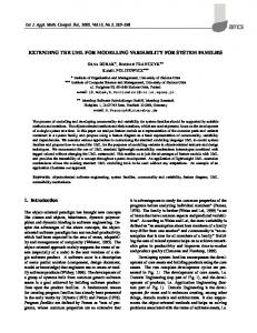
plex mission control and safety critical systems including air traffic control, such as OASIS [16]. Until recently few proposals for Agent Oriented Software Engineering and extensions to UML have been reported [5, 24, 22]. This should be contrasted with the object-oriented (OO) paradigm that is supported by modeling languages such as UML and a variety of CASE tools that aid during the analysis, design, implementation and validation phases of OO software systems: all of which contributed to the universal acceptance of the OO paradigm. In this paper, we propose a framework based on extensions to UML to support multi-agent systems (MAS) development. Our approach is rooted in the BDI formalism [21], but stresses practical software design methods instead of reasoning theories. In particular, we propose to extend UML [2] with modeling constructs called Agent, Belief, Goal, Plan, FIPA Performative, KQML Performative, and Blackboard. Agent is the super-type for all agent types. Belief, Goal and Plan model the reactive and proactive behaviors of agents. An agent has, among other data types, a collection of beliefs, goals and plans. Belief s are the agent’s observations and/or sensing of the environment and are updated by sensors or other agents. Changes in an agent’s beliefs trigger the re-evaluation of the utility values of goals of the agent. Changes to goals’ utility values result in pre-empting some plans and initiating new plans. Execution of plans affects the environment which in turn changes the beliefs, and so on. Agent communicate with each other through agent communication performatives such as FIPA [4] or KQML [7], or shared blackboards as in Linda or its extensions [18]. Figure 1 shows the conceptual model of our framework. We introduce Agent Goal Diagram (AGD) to model the relationships between the goals and the environment, the Use Case Goal Diagram (UCGD) to relate use cases and goals, Agent Domain Model (ADM) to facilitate understanding of domain knowledge of an agent, Agent Sequence Diagram (ASD) to model interactions within an agent. Similarly, Agent Activity Diagram and Agent Statechart Diagram are introduced. In the next section we review background materials. Section 3 presents new modeling constructs as well as new diagrams for MAS modeling. The extensions are illustrated in section 3.3. Related work is discussed in section 4 and conclusions and future work is in section 5.
2.2
Environment
Beliefs
Beliefs FIPA Goal
Plans
Plans
Goal
KQML Environment Beliefs
Plans
Blackboard
Goals
Figure 1: A conceptual model for the framework
2. 2.1
BACKGROUND Agents Versus Objects
An object is an entity that encapsulates state and behavior while a class is a template from which objects can be created. Every object is an instance of a class. There is no accepted definition of what “agent based” or “agent oriented” programming means. However there is a generally accepted list of characteristics associated with agents including situatedness, autonomy and flexibility. Situatedness implies that agents receive input from an environment and perform actions that may change the environment. Agents must be flexible in the sense that they should be both reactive (timely response) and proactive(goal-oriented behavior). Agents are autonomous in the sense that they do not require external intervention to carry out their tasks and may refuse to service a request1 . OO programming encourages encapsulation of object state and behavior but it is sometimes desirable to share beliefs among agents via a knowledge base or a blackboard. Agents have reactive as well as proactive goals and behaviors. The behavior of an agent may be different over time and may be non-deterministic. Agents may inherit plans (which are similar to methods), beliefs (which are similar to instance variables) and goals (for which there is no direct counter part in OO). The Unified Modeling Language (UML) [2] is a widely used standard in the OO paradigm for software requirements analysis and software design. While UML is an excellent modeling language for OO systems, it lacks the capability to readily model and specify multiagent systems. This is due to the fundamental differences between OO systems and agentbased systems. Objects are passive components whereas agents are autonomous. Objects are reactive whereas agents are proactive and situation-aware. 1
In our framework, this is implicitly accomplished by the utility values of goals. That is, when beliefs change, goals are evaluated to re-assign utility values. The utility values affect which goal(s) to pursue; and hence, the request may not be serviced if the associated goal yields a low utility value.
BDI Formalism
The BDI architecture associates with agents, beliefs (typically about the environment and other agents), desires or goals to achieve, and intentions or plans to act upon to achieve its desires. In formal terms, one can utilize logic to describe these components and reason about MAS. In practical terms, beliefs can be viewed as the state of the world. Desires (or goals) may be associated with a utility value so that desires can be differentiated. Desires can be evaluated using “path formulas” whereby all possible paths associated with a desire can be evaluated. In practical terms, evaluation functions can be used to dynamically update goal values. Intentions reflect the actions that must be exercised to achieve the goal values. Thus intentions indicate the actions along a path formula in the decision tree used to compute goal values.
3.
EXTENDING UML
The framework is aimed to provide a modeling language to help application engineers to focus their effort on agentoriented modeling rather than having to define and construct an agent model from the scratch. We introduce a number of modeling constructs with model-defined structural and behavioral features and relationships to support the BDI model. These constructs are Agent, Belief, Goal, Plan, FIPA Performative, KQML Performative and Blackboard. Agent is the basic modeling construct. Agent has Belief, Goal and Plan instances, which are related as explained in section 2.2. Agent, Belief, Goal and Plan are implemented as abstract classes in the proposed framework. Application specific BDI agent (resp. belief, goal, plan) types are implicitly defined as subclasses of Agent (resp. Belief, Goal, Plan); and hence, they inherit the model-defined structural and behavioral features and relationships. As in OO, concrete, application specific types must implement the inherited abstract features. In this way, the framework enforces the BDI model but also provides the flexibility for implementing application specific behavior, including re-using an existing design or implementation. In general, beliefs may be shared and modified by other agents. This can be achieved either by direct communication using KQML [7] or FIPA-ACL [4] messages, shared knowledge-bases or blackboards (e.g., Linda or its extensions such as LIME [18]). Goals can be proactive or reactive – proactive goals reflect the desires of an agent. These goals may impact how an agent reacts to external events (including the possibility of ignoring external stimuli — accomplished by ignoring/giving up goals with lower utility values). Reactive goals reflect how an agent can be situated in an environment.
3.1
New Modeling Constructs
The following provides (albeit an incomplete) list of new modeling constructs for MAS. An agent specification language (ASL) in BNF is given in [12]. Belief: Belief has a name for identifying Belief instances, a set of user-defined, application dependent annotations, and a list of goals that may be affected by changes to the belief. Examples of application dependent annotations are sampling frequency and probability of change of sensed values. Belief has methods for querying and updating a belief
and relating goals with a belief. When a Belief instance is change, the affected Goal instances are informed, see below. Goal: Goal has a name, a utility value, set and get functions, and a plan to accomplish the goal. The utility value of a goal indicates how valuable the goal is to the overall goal of the system. In addition, Goal has two abstract functions: beliefChanged(b: Belief ) and eval():real. The former is automatically invoked by a changed belief that affects the goal. It allows the goal to respond to belief changes. The utility values are real values between 0 and 1 with 0 representing unreachable goals. The implementation of eval() is application dependent and can be a conventional decision tree, Computational Tree Logic (CTL) derivations as described in [20], or any other evaluation mechanism appropriate for the type of agent. Plan: Plan has an identifying name and an abstract execute() method which can be invoked by a Goal object to start a plan. A subclass of Plan must implement the execute() method according to the concrete plan. The implementation may invoke KQML/FIPA performatives to communicate with other agents as well as perform conventional and knowledge based computations. In general, plans can be implemented by the command pattern [8]. The generic command class may implement Thread and the command subclasses each implements an action of the agent. A plan can be defined as a sequence of command objects and dynamically generated according to the reasoning steps. Plan also has a stop() method which can be invoked to terminate the plan. Beliefs, Goals and Plans: These are collections of Belief, Goal and Plan objects and provide standard operations for querying, inserting, updating and deleting an element. These collections also have operations of their respective component types and delegate the call to each of the component type instances. FIPA, and KQML Performatives: There are two Command Patterns [8] introduced to accommodate all the FIPA and KQML speech act performatives, respectively. Their subclasses are named after the performatives, each subclass implements the functionality of one performative. New speech act performatives can be supported by introducing additional command patterns. FIPA, and KQML Interfaces: These interfaces define method signatures that correspond to FIPA and KQML performatives, respectively. Again, new speech act performatives can be supported by introducing additional interfaces. Agent: Agent is the superclass for all agent types. It has Beliefs, Goals, Plans and methods to select the optimal goal. It has an abstract goalValueChanged (g: Goal) method, which is automatically invoked when a goal instance is changed. Agent implements both FIPA and KQML Interfaces and delegates the implementation of the performatives to the appropriate FIPA or KQML Performative subclasses. This way our framework accommodates both FIPA and KQML performatives and their extensions.
Blackboard: This is a concrete class, supported by the Singleton Pattern and Flyweight Pattern [8], to permit the use of shared blackboards. Agent can define polymorphic methods for reading, removing, writing, and appending to the blackboard (similar to Linda or LIME [18]). Figure 2 shows the nations for above modeling constructs.
3.2
New Diagrams
In this section, we describe a number of new diagrams. Their use is illustrated in section 3.3: Agent Goal Diagram (AGD) An AGD depicts the goals of an agent and their relationships to the environment. In addition, an AGD depicts relationships among the goals like goal-subgoal relationship. An AGD can also illustrate roles of an agent. For example, a goal of an auction agent playing the role of a buyer could be ”minimize cost”. The same agent when playing the role of a seller could have a goal to ”maximize profit”. Thus, the AGD for AuctionAgent/Buyer would contain ”Minimize Cost” as a goal while the AGD for Auction-Agent/Seller would contain the goal ”Maximize Profit”. Use Case Goal Diagram (UCGD) A UCGD combines the existing Use Case Diagram (UCD) and the AGD and shows the relationships between use cases and goals. That is, which use cases would affect which goal and vice versa. This information provides a high level guidance to Agent Sequence Diagram (ASD) construction. It can also be used to check the consistency between UCGD and ASD. Agent Domain Model (ADM) In OO development, a System Domain Model (SDM) documents domain object classes and their attributes and relationships. The existing SDM is extended to include agents as domain concepts. Unlike an SDM, an ADM represents the domain knowledge that is internal to an agent, including the definitions of the agent’s Beliefs, Goals and Plans and their intrinsic relationships. Agent Sequence Diagram (ASD) An ASD depicts interactions among the beliefs, goals, plans and other objects of an agent to collectively carry out a task. It is a refinement of an agent. Agent Design Diagram (ADD) ADD is introduced to document the design of an agent, derived from the corresponding ADM and ASD and implemented as a package in Java or a module in C++. This facilitates the re-use of an agent’s design and/or implementation because an application can simply import a package or a module. Agent Activity Diagram (AAD) and Agent Statechart Diagram (ASCD) These diagrams are introduced to model the internal activity and information flows and the internal state behaviors of agents.
3.3
An Example Application
In this section, we illustrate the framework using an intelligent elevator system (IES) example. We use IES for its simplicity and widely known functionality. In addition to the common features of an elevator system, IES must optimize
Belief Beliefs
Goal
Plan
Agent
Goals
Plans
Agents
Blackboard
Figure 2: Graphical notations the service and minimize the total movements of all cars to reduce energy consumption and wear. Optimizing the service may be accomplished by minimizing the response time to requests. In addition, distributed decision making among the elevator agents are assumed. A detailed description of IES can be found at http://www.uta.edu/faculty/kung/doc/elevator.pdf. We adapt the Unified Process described in [15] and perform the following steps in each increment: Step 1) Identify use cases and goals from requirements Step 2) Refine use case diagrams and goal diagrams Step 3) Refine system domain model and agent domain models Step 4) Specify sequence diagrams and agent sequence diagrams Step 5) Refine design class diagrams Step 6) Refine other diagrams We will follow steps 1) – 4) to illustrate the modeling concepts, notations and diagrams. We skip steps 5) and 6). Step 1) Identify use cases and goals from requirements. From the elevator requirements and experience we identified the following use cases: Go to Floor, Request Elevator, Open Door, Close Door. The agent goals are: Minimize Response Time and Minimize Movement. The Minimize Response Time goal attempts to reduce the response time by serving the older requests as early as possible while the Minimize Movement goal tries to reduce the movement distances by servicing the closest requests. Step 2) Refine use case diagrams and goal diagrams. In this step, new use cases and goals are added and existing ones are revised. The use cases and goals are shown in use case diagrams and goals diagrams, respectively. The UCGD for the IES example is shown in Figure 3.a. The elevator subsystem box shows the use cases and the actor (the passengers of the elevator). The diagram also contains a box representing the Elevator Car Agent; recall that the notation for an agent is the smiley face icon. The goals of the agent are shown as ovals with a curly paper icon. An association is drawn between the use case “Request Elev.” and the two goals signifying that when a passenger requests an elevator the two goals will be affected. These goals are sometimes conflicting wherein the agent takes a decision on which goal to pursue. The use case diagram is the same as conventional UML and
hence we will not repeat here. Goal diagrams are similar to use case diagrams. Figure 3.a shows a goal diagram on the right. In addition to the goals, a goal diagram may also specify relationships among the goals using UML modeling constructs like inheritance, aggregation and association. Step 3. Refine system domain model and agent domain models. In this step the system domain model [15] — an ontological or conceptual model [14] for the application domain objects, their attributes and relationships — is constructed or refined for the current increment. The system domain model for the elevator example consists of objects representing various parts of an elevator. Since the domain model has been addressed elsewhere [15], we will not repeat here. We introduce the Agent Domain Model (ADM) to capture the application dependent beliefs, goals and plans of an agent and their properties and relationships. In our approach, an ADM is constructed for each type of application specific agent. Figure 3.b shows an ADM for the elevator example. The diagram indicates that the Elevator Car Agent has two beliefs: ElevCarState and Requests. These beliefs are implicitly defined as subclasses of Belief indicated by the cloud icon. Changes to the Requests belief will affect the two goals as shown in the diagram. Similarly, the two goals are subclasses of Goal and hence must implement the beliefChanged (b: Belief ) method. The diagram also indicates that the goals have plans and each plan delegates its task to a command object [8] that implements a thread. Step 4. Specify system and agent sequence diagrams. For each use case, at least one system level sequence diagram is constructed to document how the agents and other objects work together to accomplish the business process underlying the use case. This is the same as in OO modeling [15, 2] except that agents may communicate with other agents and interact with objects (e.g., opens/closes an elevator door). Similarly, Agent Sequence Diagrams are constructed to show the intrinsic interactions within an agent, as illustrated in Figure 3.c. We have adopted the notation (i.e., the 3 with a “X” in it) proposed by O’Dell et al to represent exclusive-or interaction [19]. In Figure 3.c, the beliefs, goals and plans are encapsulated in a folder icon. This hints that the components of an agent are to be designed and implemented as a package in Java or a module in C++ to facilitate design and code re-use. Within the folder icon, there is an instance of ElevatorCarAgent. This is typical in our framework and the instance serves as both
c) Figure 3: a)Use Case Goal Diagram. b) Agent Domain Model c) Agent Sequence Diagram for the elevator example.
the container of the agent’s beliefs, goals and plans and the controller/coordinator [15, 8] for the agent. That is, the ElevatorCarAgent instance coordinates the beliefs, goals and plans. Figure 3.c shows a Blackboard that is used by the ElevatorCarAgent instances (for a multi-car elevator system) to communicate asynchronously. It is assumed that when a floor button is pressed, the request is posted to the blackboard. The agents asynchronously read (represented by the dashed arrow line labeled by “x=read()”) the blackboard to retrieve the requests and update the local belief “r: Requests”. It is assumed that the reading is triggered by some event like a timer going off or the elevator car approaching a floor. The beliefChanged (self) methods of the two affected goals are simultaneously invoked, where “self” refers to the calling object, i.e., the collection of requests. Recall that beliefChanged (b: Belief) is an abstract method of Goal. Any application specific goal type must implement this method. This way our approach forces and allows an application engineer to implement application specific responses to changes in the environment. As shown in Figure 3.c, the goals first request the Belief instance ElevCarState which stores the car’s current floorNo, direction and load. The goals then invoke their respective eval() methods to compute the utility values. The goals then fire the goalValueChanged (self) event to inform the agent that the utility values of its goals have changed. The agent then gets the utility values from the goals and pursues the higher utility goal. When the selected goal is pursued, it generates a plan and executes the plan, which delegates its task to a command object that implements Thread. The abstract function eval() of Goal must be implemented by subclasses of Goal. For the elevator example, the following Java pseudo code illustrates how the two goals evaluate differently. It is assumed that an ArrayList r of size equals to the number of floors is used to store the requests. If there is no request from a floor then the status of the request is “null”. class MinimizeResponseTime extends Goal { // ... public double eval() { if (elevCar is going up) get requests above current floor if (elevCar is going down) get requests below current floor if (elevCar is idle) get all requests process the above requests satisfying oldest and same direction requests first double u=longest waiting time/threshold; if (u>1) return 1 else return u; } }
class MinimizeMovement extends Goal { // ... public double eval() { if (elevCar is going up) satisfy requests above current floor in that order if (elevCar is going down) satisfy requests below
current floor in that order if (elevCar is idle) satisfy requests in either side that require min movement per request double u=longest waiting time/threshold; if (u>1) return 0 else return 1-u; } }
In step 5, we derive the design class diagram from the system domain model and sequence diagrams and the Agent Design Diagrams from the Agent Domain Models and Agent Sequence Diagrams. In particular, the domain model provide information to define the structural aspect while the sequence diagrams provide information for the behavioral aspect. For agents, beliefs, goals and plans that have nontrivial activity and/or behavior, the corresponding Agent Activity Diagrams and Agent Statechart Diagrams are also defined.
3.4
Discussion
In our framework, flexible relationships as well as interactions among the agents are accomplished through FIPA performatives, KQML performatives, or Blackboard. The speech act performatives allow an agent to communicate with another agent of her choice. In particular, to query the capabilities of other agents and then request services. Agents can create and/or subscribe to a common blackboard to form a group. It is also possible to define group hierarchies through the use of blackboard messages. Role dependent beliefs, goals and plans of an agent can be accomplished by generalization/specialization or inheritance. That is, treating roles as derived agent types of a more general agent type. Instances of the derived types can be used to represent different roles of the agent (which is an instance of the more general agent type).
4.
RELATED WORK
In this section we will limit our review of research projects in the area of agent oriented methodologies that are based on UML and/or BDI like agents. For more details on other methodologies we refer the reader to surveys in [23] and [10]. Rumbaugh et al’s Object Modeling Technique (OMT) was adapted by Kinny et al [13] to translate the Belief, Goal, Plan and Agent Models to formal models like BDI, our approach provides modeling and implementation with the advantage of using application specific design and implementation alternatives. This is achieved by the use of abstract classes (Agent, Goal, Belief and Plan) and design patterns as the underlying implementation model to provide the power and flexibility to support all possible needs. UML based modeling approaches have taken the front stage at International Workshops on Agent-Oriented Software Engineering (AOSE) [5] [24], The agent UML (AUML) approach proposed by Odell et al [19] introduces the Agent Interaction Protocol (AIP) for agent communication and constraints on messages. We have adopted their notations for modeling unconditional, inclusive-or and exclusive-or interactions as shown in Figure 3.c. Yim et al. [25] proposed an architecture-centric design method based on OO
design methods, design patterns and software architecture. They denote agent, agent messages, and other concepts using UML stereotypes. Bergenti and Poogi [1] treat agents as communicating entities. Similar to Yim et al, this approach uses UML to model MAS and requires no extension to UML. In addition, a Belief Model, a Goal Model and a Plan Model were proposed to specify the beliefs, goals and plans for agents. In contrast, we propose to extend UML from ground-up by introducing the concept of an Agent. Methodology for Engineering Systems of Software Agents (MESSAGE/UML) proposed by Caire et al [3] describes an analysis process that consists of various levels with more detail added to the views at each level. The analysis model consists of different “views”: 1) Organization view, consisting of entities in the system like agents, organizations, roles and relationships between them. 2) Goal/Task view, showing goals, tasks, situations and dependencies amongst them (this is similar to our Agent Domain Model). 3) Agent/Role view, describing agents and their roles. 4) Interaction view, describing the interactions amongst the agents/roles, the initiator of the interaction, the events that trigger the interaction. 5) Domain view, which is the same as a (System) Domain Model in our framework. Our modeling approach is use case centric and derives heavily from the Unified Process [15]. The Tropos methodology [9] covers a wide range of software development phases and emphasizes on requirements analysis. The methodology has a modeling language, which is not based on UML. It consists of the following phases: 1) the early requirements phase to identify goals, 2) the late requirements phase to identify the requirements for the actors, 3) the architectural design phase to assign goals and tasks to actors, 4) the detailed design phase to produce the details of actors and their communication and coordination protocols, and 5) the implementation phase. It is based on BDI concepts and introduces new notations. Unlike our approach, Tropos does not provide a framework and suggests that developers choose a framework for implementation.
5.
CONCLUSIONS AND FUTURE WORK
We have described a framework and the necessary extensions to UML to address the modeling and design of MAS including modeling constructs like Agent, Belief, Goal, Plan, FIPA Performative, KQML Performative, and Blackboard. Our approach draws from the BDI formalism. Agents are peers in the decision making process. The communication between agents is demonstrated by using a black board mechanism. Our approach allows the flexibility of using FIPA, KQML or any other agent communication languages. Various diagrams are introduced, based on UML notations. The modeling process uses Agent Goal Diagram to relate an agent’s goals with its environment, Use Case Goals Diagram (UCGD) to associate use cases with goals, Agent Domain Model to describe application specific beliefs, goals, plans and their relationships. Our framework utilizes interfaces and abstract classes to provide flexibility in implementing application specific intelligent behaviors. The sequence diagrams from UML are used to portray interactions among agents. To model the decision making process and interactions within a agent, we proposed Agent Sequence Diagrams.
We are in the process to complete the implementation of the IES (explained in 3.3) using the methodology discussed in this paper. We plan to apply the framework to modeling and design of intelligent agents for MavHome smart home project[6]. The MavHome consists of a hierarchy of intelligent agents that perceive the environment through sensors and act upon the environment to maximize the comfort of its inhabitants and minimize home maintenance costs. As future work, we will design and implement a Computer Aided Software Engineering (CASE) environment to provide modeling, design and analysis support to large-scale multiagent systems development.
6.
ACKNOWLEDGMENTS
The authors want to thank the anonymous reviewers for their constructive comments.
7.
REFERENCES
[1] F. Bergenti and A. Poggi.“Exploiting UML in the design of Multi-Agent systems,” Proceeding of the ECOOP Workshop on Engineering Societies in the Agents World 2000 (ESAW 00), pp. 96-103,2000. [2] G. Booch, J. Rumbaugh and I. Jacobson, “The Unified Modeling Language User Guide,” Addison Wesley, 1998. [3] Giovanni Caire, Francisco Leal, Paulo Chainho, Richard Evans, Francisco Garijo, Jorge, Gomez, Juan Pavon, Paul Kearney, Jamie Stark, Philippe Massonet, “Agent oriented analysis using MESSAGE/UML,” Proc. of 2nd International Workshop on Agent Oriented Software Engineering, pp. 101-108, Montreal Canada, August 2001. [4] L. Chiariglione, “FIPA 97 Specification,” http://leonardo.telecomitalialab.com/fipa/spec/fipa97/ fipa97.htm. [5] Paolo Ciancarini and Michael Wooldridge (eds.), “Agent Oriented Software Engineering,” Proc. First International Conference on Agent Oriented Software Engineering, Springer, 2000. [6] Diane Cook, http://ranger.uta.edu/smarthome/links.html. [7] T.Finn,Y.Labrou and J.Mayfield, “KQML as an agent communication language,” in Software Agents, edited by J.Bradshaw, MIT Press, Cambridge, 1977. [8] E. Gamma, et al. “Design Patterns: Elements of Reusable Object-Oriented Software,” Addison-Wesley, 1995. [9] Fausto Giunchiglia, John Mylopoulos and Anna Perini, “The Tropos software development methodology: process, models and diagrams,” Proc. of International Conf. on Autonomous Agents and Multiagent Systems: Part 1, 2002, Bologna, Italy, 2002. [10] C. Iglesias, M. Garijo, and J. C. Gonzales. “A survey of agent-oriented methodologies”. In Intelligent Agents V: Proceedings of the ATAL’98, volume 1555 of LNAI. Springer, 1999.
[11] N.R.Jennings,K.Sycara and M.Wooldridge, “A roadmap of agent research and development,” in Autonomous Agents and Multi-Agent Systems ,Kluwer Academic Publishers. [12] Krishna Kavi, Mohamed Aborizka and David Kung, “A framework for designing, modeling and analyzing agent based software systems,” in Proc. of 5th International Conference on Algorithms & Architectures for Parallel Processing, October 23-25, 2002, Beijing, China. [13] David Kinny and Michael Georgeff, “Modeling and Design of Multi-Agent Systems,” In Proc. of the 3rd Int. Workshop on Intelligent Agents: Agent Theories, Architectures, and Languages, ATAL’96, pages 1–20, Budapest, Hungary, Aug. 1997. [14] D. Kung, “Conceptual modeling in the context of software development,” IEEE Trans. on Software Eng. Vol. 15, No. 10, pp. 1176 - 1187, (Oct. 1989). [15] Craig Larman, “Applying UML and Patterns,” Prentice Hall, 2001. [16] M. Ljunberg and A. Jucas, “The OASIS air traffic management system”, Proc. of the 2nd Pacific Rim International Conference on AI, Seoul, Korea, 1992. [17] P. Maes, “Agents that reduce work and information overload”, Communications of the ACM, 37(7), pp. 31-40. [18] A.Murphy, G.Picco and G. C.Roman, “LIME: A middleware for physical and logical mobility,” Proceeding of the 21 st International Conference on Distributed Computing Systems (ICDCS),April,2001,pp 524-533. [19] James Odell, H. Van Dyke Parunak and Bernhard Bauer, “Extending UML for Agents,” AOIS Workshop at AAAI 2000. [20] A. Rao and M. Georgeff, “Modeling rational agents within a BDI architecture,” Proceedings of the Second International Conference on Principles of Knowledge Representation and Reasoning, Cambridge, MA, 1991, pp. 473-484. [21] A. Rao and M. Georgeff, “BDI agents: From theory to practice,” Proceedings of the First International Conference on Multi-Agent Systems (ICMAS-95), San Francisco, pp. 312-319. [22] “1st International Workshop on Software Engineering for Large-Scale Multi-Agent Systems,” Orlando, Florida, USA, in conjunction with ICSE 2002, May 19, 2002, [23] Tveit, A. “A Survey of Agent-Oriented Software Engineering”. NTNU Computer Science Graduate Student Conference, Norwegian University of Science and technology, 2001. [24] M. Wooldridge, G. Weib and P. Ciancarini (eds.), “Agent Oriented Software Engineering II,” Proc. Second International Workshop, Montreal, Canada, May 29, 2001, Springer 2001.
[25] H. Yim, K. Cho, K. Jongwoo and S. Park, “Architecture-Centric Object-Oriented Design Method for Multi-Agent Systems,” in Proc. of the Fourth International Conference on Multi-Agent Systems (ICMAS-2000), 2000.