EXTENDING THE UML FOR MODELLING ... - Semantic Scholar
Recommend Documents
families and propose how to extend the UML for the purposes of modelling variants in object-oriented analysis and design techniques. We recommend the use ...
Apr 19, 2001 - to suit not only different software design paradigms but to also support a ..... Effort in building custom, language specific tools or integrated ...
Sergio Luja´n-Mora, Juan Trujillo , Il-Yeol Song,. : A UML ... Sergio Luján-Mora, Juan Trujillo: extending Uml ... Esperanza Marcos, Bel´en Vela, Jos´e Mar´ıa.
dia elements. The approach is exemplified by describing the design of a web-based conference manager. Keywords. Web applications, Web Design, UML, HDM.
trated by a photograph, advertising text and the discounted price. Information about the ...... television, Web service interaction, workflow management and so on.
aspects of Web applications than pure UML, they have not reached the level of acceptance and diffusion of UML modelling tools. As a consequence, developers ...
prefabricated core, systems can be build faster. Modeling and development of common parts and variants have to be supported by methods and notations.
Modeling* sergio Luján-Mora1, Juan Trujillo1, and Il-Yeol song2 ..... Marcos, e., Vela, B., Cavero, J.M.: extending UML for Object-Relational Database. Design.
machine-readable ontologies on the web. DAML was designed to support tractable reasoning. We have been developing tools for developing ontologies in the ...
clients, hardware designers, software designers, system designers, analysts, ... complexity, ESs designer have resorting to software and system engineering and ...
object-oriented modelling fits well with people's intuitive models of the world [4]. UML is a ..... (FIPA) [20] are widely accepted as providing a good foundation for.
electronically sign all the patient's reports. It is important to clarify that the sub-goals that appear in Figure 4 as partially satisficed (P) were considered satisficed ...
In the last years, some proposals to extend the UML for database design have been ... that specifies how specific UML model elements are customized and ... UML 1.4 [10] includes a standard profile for modeling software development ...
Extending UML for trajectory data warehouses conceptual modelling. Wided Oueslati#1, Jalel Akaichi*2. Computer Science Department, Higher Institute of ...
Enterprise Architect is an intuitive, flexible and powerful UML analysis and ...
Import a UML Profile ...... For more information on Patterns, see the UML Patterns.
Apr 12, 1991 - Department of Computer Science, Concordia University. 1455 de .... Set C] for some class C. In classical object oriented programming, these would be imple- mented as ... 11] de ne \associations" to be user- ... Smalltalk and towards st
Keywords: hypermedia modelling, behavioural model, UML, personalised .... cation is intended to provide information from the subdomain of Software ...
is solely based on semantics techniques such as SPARQL update. ... This article is published online with Open Access by IOS Press and distributed under the ...
Email : [email protected][email protected] ..... produce first-cut class and interaction diagram for new domains ... (Build/Buy xUML compiler) ...
MSc and PhD degrees. Research projects in spatial information processing, ...... AAAI/MIT Press, 1997. [KSL,1994] Knowledge Systems Laboratory. The Frame.
[7] Thompson, John B, Structured Programming with COBOL and JSP, John Barrie Thompsom and Chartwell-Bratt Ltd,. 1989. [8] Yang, H; Luker, P and Chu, W, ...
While addressing these problems, it becomes necessary to develop so-called fuzzy self-adaptive software systems with the capability to deal autonomously with ...
EXTENDING THE UML FOR MODELLING ... - Semantic Scholar
We examine various approaches to customizing the standard modelling language UML to ... Keywords: object-oriented software engineering, system families, ...
Int. J. Appl. Math. Comput. Sci., 2002, Vol.12, No.2, 285–298
EXTENDING THE UML FOR MODELLING VARIABILITY FOR SYSTEM FAMILIES S ILVA ROBAK∗ , B OGDAN FRANCZYK∗∗ K AMIL POLITOWICZ∗∗∗ ∗ ∗∗∗
Institute of Organisation and Management, University of Zielona Góra Institute of Computer Science and Management, University of Zielona Góra ul. Podgórna 50, 65–246 Zielona Góra, Poland e-mail: {S.Robak,K.Politowicz}@iiz.uz.zgora.pl ∗∗
The process of modelling and developing commonality and variability for system families should be supported by suitable methods and notations. The object-oriented methods and their notations, which are used at present, focus on the development of a single system at a time. In this paper we analyse feature models as a representation of the common parts and variants contained in a system family, and propose using a feature diagram as a basic representation of commonality, variability and dependencies. We examine various approaches to customizing the standard modelling language UML to model system families and propose how to extend the UML for the purposes of modelling variants in object-oriented analysis and design techniques. We recommend the use of UML standard lightweight extensibility mechanisms (stereotypes combined with tagged values) without changing the UML metamodel. This enables us to join the advantages of feature models with UML and provides the traceability of a concept throughout system development. An application of lightweight UML extension mechanisms allows the existing standard UML modelling tools to be used without any adaptations. An example of an application illustrates our approach. Keywords: object-oriented software engineering, system families, commonality and variability, feature diagram, UML extensibility mechanisms
1. Introduction The object-oriented paradigm has brought new concepts like classes and objects, inheritance, dynamic polymorphism and dynamic binding to software engineering. Despite the advantages of the above concepts, the objectoriented software paradigm has not reached productivity, which had been expected in the area of reuse, adaptability and management of complexity (Webster, 1995). The object-oriented approach mainly supports the reuse of assets (especially of a code) in the next versions of a single software product. A software asset is a description of some partial solution (component, design document, model or knowledge) that engineers use to create or modify software products (Withey, 1996). The development of a group of systems built from common generic software assets is a goal achieved by building software productlines upon the product families. A fundamental reason for creating program families has already been presented in the early works by Dijkstra (1972) and Parnas (1976). Program families are defined by Parnas as “sets of programs, whose common properties are so extensive that
it is advantageous to study the common properties of the programs before analyzing individual members” (Parnas, 1976). The family is further (Weiss and Lai, 1999) “a set of items that have common aspects and predicted variabilities”. According to Weiss and Lai, the term variability is defined as “an assumption about how members of a family may differ from one another” and commonality is “an assumption that is true for all members of a family.” Building the sets of related systems helps us to achieve remarkable gains in productivity and improves time-to-market and product quality (Clements and Northrop, 1999). Developing system families encompasses the development of core assets and building products using the core assets. The two complete development cycles are presented in Fig. 1.: The development of core assets, i.e. Domain Engineering (top part of Fig. 1), and the development of products, i.e. Application Engineering (bottom part of Fig. 1). Domain Engineering is the development for reuse and it embraces creating, among other things, domain models and architectures. It also supplements the object-oriented methods and helps us solving problems associated with the reuse of software assets, i.e.
S. Robak et al.
286 their identification, documentation, classification, coordination, integration and evolution. Application Engineering, the development with reuse, is the process of using the results from Domain Engineering (domain assets) to produce (possibly to generate) system family members, i.e. concrete software systems. New products can be developed upon core assets as core assets may also be extracted from the existing products. Both the processes (Domain Engineering and Application Engineering) are different from a typical object-oriented process such as the Unified Process (Kruchten, 1998), aimed at developing one system at a time (i.e. System 1 or System 2 or System 3, etc. in Fig. 1).
tions and between the distinct versions of the same evolving system. There is a lack of object-oriented means (e.g. in the UML) for modelling variability in a way that could be independent from the implementation mechanisms representing it. Feature diagrams within the feature models that are used in the Domain Analysis, the first part of Domain Engineering, are such means for describing the selection rules for system family members. We believe that the contribution of this paper is that it proposes to integrate the feature diagrams’ advantages when modelling variability into the UML diagrams, in a way conforming to the UML metamodel. It also presents a survey comparing various significant
Fig. 1. Developing system families with Domain Engineering.
The Unified Modelling Language (UML) adopted by OMG (1997) as its standard modelling language has emerged as the software industry’s dominant modelling language in the object-oriented software development process. The UML is a general-purpose graphical language for specifying, constructing, visualizing and documenting workproducts that are modified or used by softwareintensive systems (Booch et al., 1999). The object-oriented approach focuses on developing one system at a time and supports neither a development for reuse, nor a development with reuse. There is a lack of distinction between the variability of different applica-
approaches to customizing the standard modelling language UML for modelling variability. In the following sections we will summarize commonality and variability as well as feature diagrams as an implementation mechanism independent representation of the common parts and variants contained in a system family. We then examine various approaches to customize the standard modelling language UML from the point of view of their suitability for expressing variability for the development of the system family, and assess them according to their support of feature modelling and their conformity to the UML metamodel, as well as a trace-
Extending UML for modelling variability for system families ability between different UML models. Then we describe an approach towards modelling variability in system families using UML standard lightweight extensibility mechanisms—stereotypes combined with tagged values. An example of an application illustrates our approach. In the last section we conclude our work.
2. Modelling Variability The common core software assets reused across systems in a product family (see Fig. 1.) are also referred to as a platform (DeBaud, 2000): “A Software Product Family is a set of related software-rich systems (products) that share a managed set of features and can therefore be built from the common software assets (the platform)”. Griss (2000) defines a product-line as a set of products that have a common set of requirements and significant variability. Members of a product-line can be treated as a program family developed and managed together to achieve economic, marketing and engineering coherence and efficiency. A product family usually extends across several domains (DeBaud, 2000). According to the UML definition by Booch et al. (1999) the domain is: “An area of knowledge or activity characterized by a set of concepts and terminology understood by practitioners in that area”. We find it useful to extend this domain definition with the applications belonging to it. Coplien (1999) uses the term “domain” to denote also the valid combinations of values for all parameters of variation for a family or for a specific parameter of the variation. Parameters of variation serve to control the instantiation of family members from the generic software assets. Collecting information about the common system requirements enables us to develop core assets as a base to develop a generic, extensible architecture. Bass et al. (1998) define the software architecture as follows: “The software architecture of a program or a computing system is the structure or structures of the system, which comprise software components, the externally visible properties of those components, and the relationships among them.” The UML definition (OMG, 1999; Booch et al., 1999) of a component is the following: “Component: A physical and replaceable part of a system that conforms to and provides the realization of a set of interfaces”.
287 Another definition of a component, given by Szyperski at the 1996 European Conference on the ObjectOriented Programming (Szyperski and Pfister, 1997), emphasizes that it needs to be a binary unit (Szyperski, 1998): “Component: A (software) component is a unit of composition with contractually specified interfaces and explicit context dependencies only. Context dependencies are specified by stating the required interfaces and the acceptable execution platform(s). A component can be deployed independently and is subject to composition by third parties. For the purposes of this independent deployment, a component needs to be a binary unit. To distinguish between the deployable unit and the instances it supports, a component is defined to have no mutable persistent state. Technically, a component is a set of atomic components, each of which is a module plus resources.” Buschmann et al. (1996) offer another definition of the software architecture: “A software architecture is a description of the subsystems and components of a software system and the relationships between them. Subsystems and components are typically specified in different views to show the relevant functional and nonfunctional properties of a software system. The software architecture of a system is an artifact. It is the result of the software development activity.” A subsystem is a set of components cooperating to achieve a specific goal, and it is a separate unit within a software architecture. According to this definition, the adequate description of software architecture requires multiple views. Noticeable examples of such architectures are to be found in methods as the Unified Process (Kruchten, 1998) and FeatuRSEB (Griss et al., 1998), both described further in Section 2.1. The architecture of a system family is better illustrated by the above definition given by Bass et al., since it describes the common overall structure as well as the commonality and variability. Frameworks, being a monolith base in the traditional object-oriented approach (Johnson, 1997), are reused in a software product-line also as components (Bosch, 2000). Gamma et al. (1994) define the notion of a framework as follows: “Framework: A set of cooperating classes that makes up a reusable design for a specific class of software. A framework provides architectural guidance by partitioning the design
288 into abstract classes and defining their responsibilities and collaborations. A developer customizes the framework to a particular application by subclassing and composing instances of framework classes.” In our terminology in the remainder of the paper, a component is merely a reusable piece of software, which is used to build more complex software. 2.1. Modelling Variability with Feature Models In the entire extent of family members, referred to as a range by Coplien, variability is used to identify the members of the software family (Coplien, 1999). According to Coplien et al. (1998), commonality is crucial to build abstractions and to enable the implementation of the common properties (features) for different systems of a domain. In comparison with that, in the conventional objectoriented analysis abstractions are used to find objects, i.e. classes. Variability as a complement of commonality should be regularized to avoid the situation when relevant features are not included or are included but never used. We remark that the feature notion in our paper (as in domain modelling) has a somewhat different meaning than the UML-feature (OMG, 1999) defined by Booch et al. (1999): “Feature: A property, such as an operation or an attribute, that is encapsulated within another entity, such as an interface, a class, or a datatype.” According to the definition by Kang et al. (1990), the feature is the property of a system which directly affects end users: “Feature: A prominent or distinctive and user-visible aspect, quality, or characteristic of a software system or systems.” Jarzabek (2000) treats features as the user’s requirements. A feature is also a distinguishable characteristic of a concept (e.g. system, component, etc.) that is relevant to some stakeholder of the concept. In this paper we introduce a more general definition of a feature: “A feature is a stakeholder (e.g. users, customers, developers, managers, etc.) visible characteristic of concept (e.g. system, component, etc.), which is used to describe and distinguish system family members.” Some features relate to end-user visible characteristics, while others relate more to a structure of a system and system capabilities (Griss, 2000; Czarnecki and Eisenecker, 2000). The feature models (Kang et al., 1990)
S. Robak et al. determine a set of the reusable and configurable requirements to determine systems and to assign significant feature combinations in a domain. In the report “Featureoriented Domain Analysis (FODA)”, Kang et al. (1990) mentioned the feature models as features models. The FODA-Method has been developed at the Software Engineering Institute, Carnegie Mellon University. The feature models represent a configuration aspect of reusable software and consist of the feature diagram, feature definitions and composition rules, and a logical basis of features. The feature diagram that forms a tree is a graphical AND/OR hierarchy of features and captures the logical structural relationships (composition and generalization) among features. A root of the tree represents a concept being described and the remaining nodes denote features. There are three feature types distinguished in the FODA: mandatory, optional and alternative ones. A feature is mandatory unless an empty circle is attached to its node, indicating an optional feature. A set of alternative features is depicted by an arc spanning two or more edges of feature nodes (Kang et al., 1990). The parent node of a feature node is either the concept node or another feature or a subfeature node. We distinguish between direct features of a concept and subfeatures (i.e. features having other features than their parents). Direct features of a software system can be mandatory, alternative, or optional with respect to all the applications within the domain. A subfeature can be mandatory, alternative, or optional with respect to applications which also have their parent feature. Mandatory features must be always included in every system instance, an optional feature may be included or not, and an alternative feature replaces another feature when included. Feature definitions describe all features including indication at which time the feature will be bound (compile time, activation time, runtime, etc.). The composition rules indicate which combinations of the features will be valid. These dependencies are usually maintained as separate constraints. According to the FODA, there are two kinds of strong constraints: requires rules and mutual inclusion (exclusion) that may not be violated. The weak constraints as described by Czarnecki and Eisenecker (2000) are the default values, which can be overridden. The logical basis for the features is the rationale for choosing a particular feature. Figure 2 shows an example of a feature diagram with possible features of a mail subscription system. Such systems are used to provide a specified kind of messages with a given frequency to subscribers (users of a system). These messages could be, e.g., product announcements, business news or usenet posts. The common features of subscription systems are, for example, the ability to register new subscribers, and cancel a subscription, and—of course—distributing messages. The optional feature is a
Extending UML for modelling variability for system families
289
Fig. 2. Feature diagram of a mail subscription system.
possibility of editing a subscriber’s data or processing statistics of the users. The user registration component could be implemented in various ways: one can send mail with a proper format accepted by the system or register using a WWW form (and submitting it with the HTTP protocol or the more secure HTTPS protocol). The possibility of choosing between the submission with the HTTP or HTTPS protocols will only be given when the alternative feature “Registering on WWW” is chosen. Domain analysis methods (Arrango, 1994) like feature analysis provide a concise and explicit representation of commonality and variability contained in a system family on a high level of abstractions. This allows us to achieve reusability above the code level on a level of specification and the design requirements. Using feature diagrams, as opposed to UML-diagrams, has a significant advantage that decisions regarding the specific mechanisms (like aggregation, inheritance, class parameterization, etc.) for representing a given variation point need not to be made in a domain analysis model. In feature diagrams variation points are the nodes with attached variable features. The notion of a variation point was first introduced in Reuse-driven Software Engineering Business (RSEB) (Jacobson et al., 1997) as a point which “identifies one or more locations at which the variation will occur.” Variability influences the software assets and they have to be able to fulfil the variability. Voget et al. (2000) define a variation point as a point in a software productline workproduct (assets) where variability emerges and give techniques for its accomplishment. Variability was classified by Coplien in his book “Multi-Paradigm Design for C++” (1999) as positive and negative. Positive variability leaves the underlying commonality model untouched and merely adds something
that refines its definition. Negative variability violates the commonality assumptions. The models of positive and negative variabilities are well developed for the objectoriented paradigm. An instance of positive variability is a public inheritance with addition as opposed to an inheritance with cancellation for negative variability (Coplien, 1999). Feature diagrams are an integral part of Generative Programming (Czarnecki and Eisenecker, 2000), a new software-engineering paradigm designated to achieve reusability, and also in some object-oriented methods like FeatuRSEB (Griss et al., 1998). Generative programming is based on modelling software system families. On the basis of a particular requirement specification, highly customized and optimized assets (end products or intermediate workproducts) can be assembled on demand from elementary, reusable implementation components by means of configuration knowledge used for mapping between the problem and configuration spaces. The problem space is a set of all valid feature combinations (domain-specific abstractions), and a set of all generic implementation software components (or concrete systems) of a domain is referred to as the solution space. Different parts of configuration knowledge can be used at different binding times (i.e. times at which the feature will be bound). The object-oriented methods, e.g., the Unified Process, being de facto a standard, UML-based objectoriented software engineering process (Kruchten, 1998; Rational, 2002), to describe the architecture of a softwareintensive system use a ‘4 + 1’-View approach adapted from (Kruchten, 1995). The four adapted views proposed by Booch et al. (1999) to denote the different areas of concerns and categories of description are design, process, implementation, and deployment views. A de-
S. Robak et al.
290 Table 1. Configuration table for three types of subscription systems.
System description: 1. S1 – common mail-based subscription system: one sends an e-mail with the word ’subscribe’ as the subject and becomes registered; the system does not provide a possibility to edit own data—one can only cancel subscription. 2. S2 – this system is web-oriented: one fills out the form (in this case this form is submitted using the HTTP protocol) and becomes registered; at the same time the user is prompted to answer some poll questions, and the content of the messages depends on this feedback; the system allows for editing user data. 3. S3 – it is a composition of mail and WWW oriented systems; there is an additional possibility to send registration data in encrypted form (SSL/HTTPS); compared with the S2 system, there are no edit and statistics modules. sign view describes the end-user functionality (in the form of UML class diagrams, interaction diagrams, state diagrams, etc.). A process view deals with concurrency, performance, scalability, throughput, etc. An implementation view is a view of software configuration management (packages, components, etc.). A deployment view shows a system topology and communication from a point of view of system engineers and the use of UML deployment diagrams, etc. The central stage in ‘4 + 1’-View fulfils the use-case-view capturing system requirements from the user perspective (scenarios). FeatuRSEB has integrated an object-oriented adaptation of the FODA (Vici et al., 1998) into Reuse-Driven Software Engineering Business (RSEB) (Jacobson et al., 1997). The central role of a ‘+1’-model (tying all other models together) is played there by a feature model designated for primary representation of commonality, variability and dependencies. Thus, FeatuRSEB is feature model centric. Griss et al. (1998) noticed that a feature model organizes system requirements from the reuser perspective.
The original feature diagrams from the FODA have been further normalized and extended with subsequent kinds of features for variations such as, e.g., or-features (Czarnecki and Eisenecker, 2000) and another kind of features, e.g. with the binding time associated directly with a feature (such as runtime bound features in FeatuRSEB). The feature diagrams are constructed to show common and variable features of different family members. Mandatory features whose parent-features are neither optional nor connected to alternatives represent common features each family member possesses. For example, the common features of subscribing systems (see Fig. 2) are registering, cancelling registration and posting messages. These common features can be realized as reusable components (Szyperski, 1998) or frameworks. The rest of the features are variable features, which represent the permissible differences between family members. A part of the implementation process of a member is selection of these variants. A configuration table containing the variable features of the member describes the choices which have
Extending UML for modelling variability for system families been made (see Table 1 for three types of mail subscription systems). A configuration table corresponds to those of model elements that are influenced by variable features. A software engineering process of developing system families using a feature model may be conducted as follows: After “scoping and economics” (DeBaud, 2000; DeBaud and Schmid, 1999) of the family of interest accomplished by analyzing project stakeholders, the next step is to determine the common and variable features as a base of the system family. The constraints and dependencies between features included in a feature model will also be considered. A domain model is designed by refining a feature model, describing common and variable features of an abstract architecture. In the next step (development phase) generic system architecture and infrastructure containing means for specifying system family members are to be built. Then reusable components and ultimately application generators are implemented. System family members are assembled (or partially generated) based on the existing assets. Implementing automatic configurations might require the use of metaprogramming techniques (Breymann, 1998). Separation of Concerns (SOC) can be achieved by disconnection of the aspects (i.e. synchronization, persistency, etc.) from functional components using aspectoriented implementation technologies (Kiczales et al., 1997). The importance of feature modelling can be summarized as follows: It characterizes system families and product-lines, and defines their scope and configurability aspect. It also serves as a basis for the design of the family architecture and implementation components. The commonality indicates reuse opportunities. In the Generative Programming feature, modelling provides the configuration knowledge required to automate the production of the family members. Finally, in order to be able to describe the selection rules for system family members, feature diagrams are required. In the next section we shall examine and discuss the known approaches in order to show how they customize different means for these purposes. 2.2. Modelling System Families The standard object-oriented notation UML does not contain any possibility of representing variation points and attached variants. In this section various approaches to modelling variability and different extensions are presented and evaluated according to their support of feature modelling, their conformity to the UML metamodel and also a traceability between the different UML models, i.e. the ability to follow and document the references of a concept throughout system development. The RSEB method introduced the notion of the variation point and variation into use cases, but has no ex-
291 plicit feature modelling. In FeatuRSEB, where a feature model represents the configuration aspect of reusable software, Griss et al. (1998) propose an implementation of the feature diagram notation by using predefined UML modelling elements. The features are implemented as classes described with a stereotype feature . An optional attribute is used to indicate whether or not a feature is optional. The special node type called the “variation point” is introduced to describe a feature with a single set of alternative subfeatures (or features) and no other direct subfeatures (or features). The relationship “composed-of” is used for features and the “alternative” relationship is used for variation points. The variation point notion in FeatuRSEB corresponds to the term dimension used by Czarnecki and Eisenecker (2000). FeatuRSEB features have a binding time flag indicating whether or not a variation point is bound at runtime (“use time”). The FeatuRSEB approach does not distinguish between different availability sites, i.e. when, where and to whom a feature can be available. It does not distinguish between different binding times, i.e. when variability is resolved (e.g. source time, compile time, link and load time, runtime) nor binding modes (e.g. static, dynamic). A statically bound feature cannot be rebound (e.g. inlining of methods in C++), in contrast to dynamically bound features, which are automatically bound before a use and unbound afterwards. The use and drawbacks of FeatuRSEB were further described by Boellert and Philippow (2000). Jarzabek (2000) proposed one of the possible methods to model commonality and variability using the UML standard notation. The extensions were proposed for all kinds of diagrams defined by UML. For example, putting variability into frames with the description ending with the word “variant” extended activity diagrams. The optional features are modelled with the decision blocks with a proper stereotype ( alt-features , or-features ). Every such alternative is marked together with the condition in square brackets. The mapping between model elements and features is additionally described in comments. Nevertheless, this approach suffers from some drawbacks: putting important information about features into comments and not into elements themselves causes model inconsistencies, for example, what if the same element is a part of more diagrams? Moreover, comments are normally not evaluated during the code generation. Thus, the reverse engineering process will result in a loss of information. Using the standard conditional notation (in the case of activity diagrams—conditions in the process flow) to model variability for a system family renders the model illegible— one never knows if a condition represents a choice of a user during runtime or of a system designer. In another approach (Gomma, 2000) commonality and variability are modelled using stereotypes Kernel
292 and Optional for predefined UML modelling elements. The features are presented as packages, and relations between them are additionally modelled with the include and extend technique. This approach makes the generation-time information usable through the whole model (each element knows its package, so it knows which feature it belongs to). However, the UML allows us to model hierarchies in one dimension only. Thus, to model features one cannot use standard application hierarchy of packages. This is the common problem for methods based on a standardized notation to render new aspects of a model—the notation can be used for only one purpose. Hein et al. (2000) presented an approach to an extension of the FODA and the representation in the UML of different types of crosslinks that are necessary to describe domains in an industrial environment. This extended feature model introduces the roles of the features enabling secondary structures to include alternative and optional consists-of crosslinks and to distinguish between unidirectional and bi-directional relationships. A feature may appear in several roles, each with its own binding time (i.e. compile, load, run) and decomposition type (string) documenting partitioning rules for a structure the next level deeper. The information contained in the “decomposition type” is destinated to describe the principles applied to breakdown a system or a product family into features and the features further into subfeatures. A mapping between UML model elements and logical elements contained in the extended feature model (all kinds of features with their roles) is realized by using UML packages which allows us to create name-spaces for same-named features participating in different structures (i.e. different branches in a feature model). All elements in the package have the same decomposition type and each package contains a dedicated class of “feature specification” (with feature attributes: binding time and decomposition type) and “trace point” (to enable links to arbitrary modelling elements). Indicating either a directed or an undirected link for connecting features (with “mutex”) shows how the derivation is done (undirected elements stop the selection process). A shortcoming of this method is the restriction of variability in feature specification to the binding time and the decomposition type. There can be also other attributes needed to choose a variant, like variability mechanisms, stakeholder, binding occurrence, description, etc. (Coriat et al., 2000). Summarizing, there are three major drawbacks in the examined existing methods, which make their practical use in software development difficult if not impossible: • Usage of untraceable graphical UML elements like comments to express variability;
S. Robak et al. • Assigning a new meaning to language elements, which have already had a common use pattern (i.e. stereotypes include and extend ); • Lack of sufficient information needed to choose a variant and to distinguish between different sites, binding times, binding modes, stakeholders, etc. In Table 2 a summary of the modelling notations is given from the viewpoint of the various presented approaches. We consider the support of feature modelling (FODA-based feature modelling or its extensions, see Section 2.1) and the use of the standard UML model elements according to their standard usage as the main criteria for the comparison. Additional criteria involve the extensions conformity to the UML metamodel (see Section 3) and additional feature information to choose a variant as described at the beginning of this section (when considering FeatuRSEB). The means for the mapping between the features and UML model elements used by the presented modelling notations are also summarized. Further in this paper we will show how to join the advantages of feature models with the standard modelling language UML and how to provide the traceability of a concept throughout system development using lightweight UML extensions mechanisms (stereotypes combined with tagged values) to omit the limitations described above. We will also present how to use this to model the desired properties of product family members.
3. Distinguishing UML Model Elements for Variability Currently the UML does not provide possibilities to indicate variable model elements because it is targeted at modelling a single system at a time rather than system families. Modelling system families (additionally sharing features coming from multiple domains), as opposed to modelling a single system, requires using notations, which contain the diagrams, extended with possibilities of distinguishing variants. The UML diagram elements describing common features of a system family are able to remain the same as in the conventional models (i.e. without any extensions). To describe model aspects of system families such as architecture, static structure, dynamic behaviour and interfaces, standard UML diagrams can be used without any modifications. It is necessary to adapt the elements of UML diagrams that are designated to express variability and distinguish between common and variable model elements. Diagram elements implementing variable features should be specifically marked to provide analysts‘ and developers‘ information about constraints between features (e.g. mutually inclusive, mutually exclusive features) and their implementation as well as information about configuration aspects of features. Such el-
Extending UML for modelling variability for system families
293
Table 2. Comparison table for variability modelling notations.
Feature modelling included: FODA-based FODA-based extension Additional featurte information to choose a variant: Availability sites Binding times Binding modes Others Modelling features in UML: Classes Comments Packages Use of standard UML model elements according to a standard usage Extensions conforming to the UML metamodel Legend: ‘+’ Yes,
‘−’ NO,
‘?’ Questionable
ements must be associated with their corresponding feature in order to provide the ability to follow and document the references of a concept throughout system development. The traceability should be supported by modelling tools and explored by CASE tools in order to allow generating parts of code automatically and to configure instantiated family members. Therefore the UML needs to be extended to model variability. This can be done either by using UML lightweight extensibility mechanisms (such as stereotypes, constraints and tagged values) or by heavyweight extension mechanisms—metaclasses (OMG, 1999). The extensions presented in the paper conform to the UML metamodel, and therefore we describe the part of the metamodel dealing with those UML extensions (see also Fig. 3). The metamodel level is (beside the meta-metamodel, model and user object layers) one layer of the UML’s four-level model architecture based on the metamodel architectural pattern (OMG, 1999; Kobryn, 1999). Metamodelling offers significant advantages. It allows formal specification of all modelling concepts (together with their attributes, constraints and relationships), defines a base for a unified exchange format and makes the extendibility of UML possible, i.e. permits instantiation of new metamodel classes as subclasses of the existing metamodel classes. All modelling concepts are in the UML referred to as model elements (e.g. classes, attributes, and operations). The UML metamodel
RSEB
FeatuRSEB
Jarzabek
Gomma
Hein et al.
−
+
+ +
−
+
− − − − − +
+ + − + − + + +
+
+
− +
− +
−
+ + − ? − − + +
− − − − − + +
? − and
? +
− +
‘blank’ Not available/not relevant class ModelElement is an abstract class (just like its direct subclasses GeneralizableElement and Feature and indirect subclasses Classifier, BehavioralFeature, etc.) with some instantiable indirect subclasses like Class, Attribute and Operation. The instances of Class are user-defined classes. At the metamodel strata, the UML metamodel consists of tree logical subpackages named Foundation, Behavioral Elements and Model Management. The Foundation package is the linguistic infrastructure specifying the static structure of models and consists of Core, Extension Mechanisms and Data Type subpackages. Lightweight extension mechanisms such as stereotypes, constraints and tagged values are represented in the UML metamodel as the metamodel’s classes named Stereotype, Constraint and TaggedValue. Although a change of the UML metamodel offers the highest degree of flexibility, we have not taken it into consideration because the metamodel is not available or difficult to modify in the existing UML modelling tools. This the reason why we use lightweight extension mechanisms defined in the UML, i.e. stereotypes, which are combined with tagged values. A stereotype is defined by Booch et al. (1999) as follows: “An extension of the vocabulary of the UML, which allows you to create new kinds of buildings blocks that are derived from existing ones but are specific to your problem.”
S. Robak et al.
294
Fig. 3. Extensibility mechanisms in the UML metamodel (OMG, 1999, pp. 2–67).
Stereotypes are a way of extending the basic metamodel to create a new model element as a subclassification of an existing model element. Stereotypes are used to mark, classify or introduce new model elements in the metamodel class hierarchy. Each model element can be marked at most with one stereotype (UML V1.3), which is depicted in front of an element’s name enclosed in double angle brackets, and/or represented graphically as an icon (OMG, 1999), see Fig. 3. The UML already predefines some stereotypes, e.g., trace , expressing the dependence between two elements rendering the same concept from different perspectives, or some common stereotypes for classes ( boundary , entity , control , exception and utility ). A tagged value is “an extension of the properties of a UML element, which allows you to create new information in that element’s specification.” (Booch et al., 1999). The tagged value is mostly a user-defined property extending the semantics of model elements. Tagged values do not have any graphic representation and are used to determine additional characteristics or attributes of model elements. Each tagged value consists of a key-value pair, which appears after an element’s name in curly braces, like a version description often added to many building blocks, which is not a primitive UML concept: {version = 1.3} (Booch et al., 1999; OMG, 1999). If more than one tagged value is associated with an element, commas separate the values. The tagged value can be related as a composition either with one stereotype or with another model element. Figure 3 depicts the part of the UML
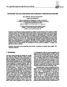
metamodel containing the described UML’s own extensibility mechanisms (OMG, 1999). To model an element which corresponds to a variable feature, we introduce a new stereotype variable and a tagged value with the tag name “feature”: Stereotype/keyword: variable Applies to symbol: Component, Action State in Activity diagram (OMG, 1999) Meaning: Variable part matching the variable feature. Tagged Value: feature Applies to symbol: Component, Action State in Activity diagram Meaning: Variable part stereotyped with variable , matching the variable feature; key value: String. Each element with the stereotype variable has to have a tagged value with the keyword “feature” defined. A key value is a string corresponding to a feature name from the feature diagram. Such an approach guarantees the traceability from the feature diagram to a system model and backward. Figure 4 shows an example of using extensions described in an UML activity diagram for registering a mail subscription (in a mail subscription system). On this diagram the subsequent steps for registering a new subscriber use case are shown. The first difference between various subscription systems can be recognized in the first branching activity: one can register by mail (with a prop-
Extending UML for modelling variability for system families
Fig. 4. UML activity diagram for registering a mail subscription.
295
S. Robak et al.
296 erly formatted message) or just fill in a WWW form (here there is a choice between the standard HTTP protocol and the more secure but slower HTTPS protocol). Activities implementing the corresponding variable elements from the feature diagram are marked with the variable stereotype. The consistency between the model and the feature diagram is maintained by using the property “feature” contained in the tagged value. The UML component diagram for implementing a mail subscription system acts in a similar way (see Fig. 5). The groups of features are modelled as packages and the features themselves (mandatory and optional features) are modelled as components. Similarly to the activity diagram, the optional components are distinguished by the stereotype variable . The tagged value “feature” corresponds to the name of the feature contained in a feature diagram (see Fig. 2). For example, “User preferences DB” component implements the optional feature “freq-user” (post frequency in the user’s preferences). Feature models can represent variation points and dependencies between them in an explicit way. With feature diagrams it is possible to differentiate between variability within a member of a software family and also between different family members. This helps us to avoid developing unnecessarily complex structures like components, frameworks containing features that are not needed, or contained but never used (Robak and Franczyk, 2001). Feature modelling also provides implementation mechanisms for representing variability. Within a configuration the features have to be selected in order to instantiate a
family member from abstract system architecture. A chosen condition is implicitly given in the feature configuration. According to the selected features, the activity diagram is processed. As a result, the semantics of the ifcondition element in the activity diagram are changed to process the selected variant set for each member of the system family. The presented approach shows the possibility of mapping the variable features in the UML. To show the principle we have to make use of one stereotype variable . The approach is not limited to the use of this one stereotype—stereotypes further rendering the exact kind of variable FODA features (i.e. optional, alternative) or FODA extensions (or-features, etc.) are possible. If needed, the technique of using tagged values can be extended to support further information necessary to choose a variant (i.e. the binding time, the binding mode, etc). One only has to define a tagged value with a proper key (i.e. “binding_time”) and assign a value to the corresponding model elements. Stereotypes and tagged values could be added to all model elements, making it possible to label each model element as being variable. The experience, however, has shown that these result in quite complex models, and they are difficult to understand and maintain without sophisticated tool support. The approach described above allows uniting the advantages of feature modelling with UML diagrams adopted for distinguishing variability. The traceability of a concept throughout system development is provided. Using only lightweight UML extension mechanisms (such
Fig. 5. UML component diagram for implementing a mail subscription system.
Extending UML for modelling variability for system families as stereotypes and tagged values) means that the existing standard UML modelling tools can be used without any extensions or adaptations.
297 In order to reach more comprehensive support for system family modelling, the next step is to integrate feature models into the UML, and specification of appropriate constructs is to be defined as a special product-line UML profile.
4. Conclusions Software product-lines have common properties and attributes and vary according to their usage by specific markets. In domain analysis there is a wider scope of abstraction than we encounter in traditional object-oriented analysis, because we have to find commonality not only within an application, but also within related application systems which form families. Commonality and variability analysis notations containing also the details of binding times, defaults and relationships between domains should support the development of reusable software for system families. Feature models provide an abstract, independent and concise representation of commonalities and variability contained in the system family, but there is no tool support for modelling features. As a standard, the UML is well suited to exchange ideas between stakeholders, but it does not provide necessary means to describe variability. The presented approach constitutes an extension to overcome this shortcoming. It proposes a consistent way of modelling the variability of system families using predefined UML modelling elements. This enables us to join the advantages of feature models with the UML and provides the traceability of a concept throughout system development. Various kinds of information needed to choose a variant (like different kinds of sites, binding times and binding modes, stakeholders, etc.) can be captured as additional properties of modelling elements and notified as pairs of tagged values. An application of lightweight UML extension mechanisms allows the existing standard UML modelling tools to be used without any adaptations. In the future we intend to provide our extensions for all relevant UML diagram elements. A more formal definition and application of diagrams will permit tool support. More concise formalization of semantics would allow the development of better consistency checking and automation tools. This is impossible without wide cooperation among the object-oriented community in order to extend the UML metamodel and the OMG standards. Variability aspects of analysis and design methods have to be investigated in detail. CASE tool support for system family development methods has to be developed. Appropriate CASE tools to achieve this aim should support the feature diagram notation and be able to manage all additional information required by feature modelling (especially the constraint management facility). It is also important to provide traceability links to other models.
References Arrango G. (1994): Domain Analysis Methods, In: Software Reusability (W. Schäfer, R. Prieto-Dıaz and M. Matsumoto, Eds.). — New York: Ellis Horwood, pp. 17–49. Bass I., Clements P. and Kazman R. (1998): Software Architecture in Practice. — New York: Addison-Wesley. Boellert K. and Philippow I. (2000): Erfahrungen bei der objektorientierten Modellierung von Produktlinien mit FeatuRSEB. 1. — Deutscher Software-Produktlinien Workshop (DSPL-1), Kaiserslautern, IESE-Report No. 076.00/E, pp. 29–34. Booch G., Rumbaugh, J. and Jacobson I. (1999): The Unified Modeling Language User’s Guide. — New York: AddisonWesley. Bosch J. (2000): Design and Use of Software Architectures. Adopting and Evolving Product-Line Approach. — New York: Addison-Wesley. Breymann U. (1998): Designing Components with The C++ STL—A New Approach To Programming. — New York: Addison-Wesley. Buschmann F., Meunier R., Rohnert H., Sommerlad P. and Stal M. (1996): Pattern-Oriented Software Architecture: A System of Patterns. — New York: John Wiley & Sons. Clements P. and Northrop L.M. (1999): A Framework for Software Product Line Practice – Version 2.0 [online]. — Pittsburgh, PA: Software Engineering Institute, Carnegie Mellon University, Available at www.sei.cmu.edu/plp/framework.html Coplien J. (1999): Multi-Paradigm Design for C++. — New York: Addison-Wesley. Coriat M., Jourdan J. and Boisbourdin F. (2000): The SPLIT method building product lines for software-intensive systems, In: Proc. Software Product Line Conf. (SPLC1), (P. Donohoe, Ed.). — Massachusetts: The Kluwer Academic Publishers, pp. 147–166. Czarnecki K. and Eisenecker U. (2000): Generative Programming Methods, Tools and Applications. — New York: Addison-Wesley. DeBaud J.M. and Schmid K. (1999): A systematic approach to derive the Scope of Software Product Lines. — Proc. ICSE’99, Los Angeles, CA, pp. 34–43. DeBaud J.M. (2000): The Truescope Approach to Software Product Family Engineering. — First Software Product Line Conference (SPLC1), Denver, USA.
298 Dijkstra E.W. (1972): Notes on Structured Programming, In: Structured Programming (O.J. Dahl, E.W. Dijkstra and C.A.R. Hoare, Eds.). — London: Academic Press. Gamma E., Helm R., Johnson R. and Vlissides J. (1994): Design Patterns – Elements of Reusable Object-Oriented Software. — New York: Addison-Wesley. Gomma H. (2000): Object oriented analysis and modeling for families of systems. — Proc. 6th Int. Conf. ICSR-6, Vienna, Austria, In: Software Reuse: Advances in Software Reusability (W.B. Frakes, Ed.), Berlin: Springer, pp. 89– 99. Griss M.L., Favaro J. and D’Alessandro M. (1998): Integrating Feature Modeling with the RSEB. — Proc. Int. Conf. Software Reuse, ICSR98, Victoria, BC, IEEE, pp. 36–44. Griss M.L. (2000): Implementing product-line features with component reuse. — Proc. 6th Int. Conf. ICSR-6, Vienna, Austria, In: Software Reuse: Advances in Software Reusability (W.B. Frakes, Ed.), Berlin: Springer, pp. 137– 152. Hein A., Schlick M. and Vinga-Martins R. (2000): Applying feature models in industrial settings, In: Proc. Software Product Line Conf. (SPLC1), (P. Donohoe, Ed.). — Massachusetts: The Kluwer Academic Publishers, pp. 47–70. Jacobson I., Griss M.L. and Jonnson P. (1997): Software Reuse: Architecture. — Process and Organization for Business Success, New York: Addison-Wesley Longman. Jarzabek S. (2000): Product Line Approach. Net. ObjectDays 2000. — Proc. 2-nd Int. Symp. Generative and Component-Based Software Engineering, GCSE’2000, Erfurt, Germany, available at: http://www.netobjectdays.org/node00 Johnson R.E. (1997): Frameworks = (Components + Patterns). – Comm. ACM, Vol. 40, No. 10, pp. 39–42. Kang K., Cohen S., Hess J., Nowak W. and Peterson S. (1990): Feature-oriented domain analysis (FODA). Feasibility study. — Technical Report No.CMU/SEI-90-TR-21, Software Engineering Institute, Carnegie Mellon University, Pittsburgh, Pennsylvania. Kiczales G., Lamping J., Mendhekar A., Maeda C., Lopes C.V., Loingtier J.M. and Irvin J. (1997): Aspect-Oriented Programming. — Proc. 11th European Conf. Object-Oriented Programming, ECOOP97, Jyväskylä, Finland, (M. Aksit and S. Matsuoka, Eds.), Berlin: Springer-Verlag. Kobryn C. (1999): UML 2001: A standarization Odyssey. — Comm. ACM, Vol. 42, No. 10, pp. 29–37. Kruchten P. (1995): The 4 + 1 view model of architecture. — IEEE Software, Vol. 12, No. 6, pp. 42–50. Kruchten P. (1998): The Rational Unified Process. — New York: Addison-Wesley Longman.
S. Robak et al. OMG (1997): Object Management Group, available at http://www.omg.org OMG (1999): OMG Unified Modeling Language Specification (draft), V. 1.3, available at: www.rational.com/uml/resources/ documentation/ (pdf-format). Parnas D.L. (1976): On the design and development of program families. — IEEE Trans. Softw. Eng., March. Rational (2002) — Available at: www.rational.com Robak S. and Franczyk B. (2001): An object-oriented evolutional approach for developing system families using frameworks. — Studies in Automatics and Computer Science, Vol. 26, Pozna´n, pp. 179–189 (in Polish). Szyperski C. (1998): Component Software: Beyond ObjectOriented Programming. — New York: Addison-Wesley. Szyperski C. and Pfister C. (1997): Workshop on ComponentOriented Programming, Summary. — Special Issues on Object-Oriented Programming, ECOOP96 Workshop Reader (M. Muellhauser, Ed.), Heidelberg: dpunkt Verlag. Vici A.D., Argentieri N., Mansour A., d’Alessandro M. and Favaro J. (1998): FODAcom: An Experience with Domain Analysis in the Italian Telecom Industry. — Proc. 6th Int. Conf. ICSR-6, Vienna, Austria, In: Software Reuse: Advances in Software Reusability (W.B. Frakes, Ed.), Berlin: Springer, pp. 166–175. Voget S., Angilletta I., Herbst I. and Lutz P. (2000): Behandlung von Variabilitaeten in Produktlinien mit Schwerpunkt Architektur. — 1. Deutscher SoftwareProduktlinien Workshop (DSPL-1), Kaiserslautern, IESEReport No. 076.00/E, pp. 23–28. Webster B. (1995): Pitfalls of Object-Oriented Development: A Guide to the Wary and the Enthusiastic. — New York: M&T Books. Weiss D.M. and Lai C.T.R. (1999): Software Product-Line Engineering: A Family Based Software Development Process. — New York: Addison-Wesley. Withey J. (1996): Investment analysis of software assets for product lines. — Tech. Rep. No. CMU/SEI-96-TR-010, ADA 315653. Pittsburgh, PA: Software Engineering Institute, Carnegie Mellon University.
Received: 26 January 2001 Revised: 15 September 2001 Re-revised: 18 March 2002