Extension of wavelet compression algorithms to 3D and 4D image data: Exploitation of data coherence in higher dimensions allows very high compression ratios Li Zeng*a, Christian Jansena, Michael Unserb, Patrick Hunziker ** a a Divisions of Cardiology and Intensive Care Medicine, University Hospital, Basel, Switzerland; b Biomedical Imaging Group, Swiss Federal Institute of Technology, Lausanne, Switzerland ABSTRACT High resolution multidimensional image data yield huge datasets. For compression and analysis, 2D approaches are often used, neglecting the information coherence in higher dimensions, which can be exploited for improved compression. We designed a wavelet compression algorithm suited for data of arbitrary dimensions, and assessed its ability for compression of 4D medical images. Basically, separable wavelet transforms are done in each dimension, followed by quantization and standard coding. Results were compared with conventional 2D wavelet. We found that in 4D heart images, this algorithm allowed high compression ratios, preserving diagnostically important image features. For similar image quality, compression ratios using the 3D/4D approaches were typically much higher (2-4 times per added dimension) than with the 2D approach. For low-resolution images created with the requirement to keep predefined key diagnostic information (contractile function of the heart), compression ratios up to 2000 could be achieved. Thus, higher-dimensional wavelet compression is feasible, and by exploitation of data coherence in higher image dimensions allows much higher compression than comparable 2D approaches. The proven applicability of this approach to multidimensional medical imaging has important implications especially for the fields of image storage and transmission and, specifically, for the emerging field of telemedicine. Keywords: wavelets, image compression, 3D, 4D, medical imaging, echocardiography.
1. INTRODUCTION High resolution multidimensional image data are increasingly used in many fields, yielding huge datasets. For example, 3D CT, 3D texture, video images, light field of 3D object, 4D(3D moving) object recognition, 4D (moving 3D) echocardiography images1, can be mentioned. For compression and analysis of these data, conventional 2D approaches2,3 are often used, neglecting the high information coherence in higher image dimensions, which could be exploited for improved compression and analysis algorithms. For 3D compression, some work have been done6. For example, volumetric medical image compression with three-dimensional wavelet transform and octave zerotree coding has been described4. To explore the potential of applying a 4-dimensional approach to 4D medical datasets, and to analyze the gains in compression efficiency when using this approach compared to conventional 2D wavelet compression, we designed a wavelet compression algorithm which handles data of an arbitrary number of dimensions in a coherent fashion and applied it to 4D (moving 3D) medical image data acquired by multidimensional echocardiography. The algorithm consists of wavelet decomposition using standard wavelet bases consecutively in each dimension followed by quantization (lossy), and standard lossless compression. Compression ratios and image quality attainable by this 4D approach were then compared with conventional 2D wavelet algorithms using similar wavelet bases. We found that in 4D image data acquired in subjects with heart disease, using this new algorithm allowed high compression ratios with retention of the image features necessary for diagnosis of heart disease within the datasets. For achievement of similar visual quality, compression ratios using the 4D approach were typically much higher than with the 2D approach. For low-resolution images created with the requirement to keep predefined key diagnostic information (contractile function of the heart) with maximum compression, compression ratios up to 2000 could be achieved. *
[email protected] phone 41 61 2655375 Current address: Dept. of Cardiology, University Hospital of Basel, 4031 Basel, Switzerland, came from Dept. of Applied Math., Chongqing University, 400044, P. R. China; **
[email protected] phone ++41 61 265 25 25; Physics in Medicine Research Group, Cardiology & Intensive Care Medicine Divisions, University Hospital, 4031 Basel, Switzerland.
Wavelets: Applications in Signal and Image Processing IX, Andrew F. Laine, Michael A. Unser, Akram Aldroubi, Editors, Proceedings of SPIE Vol. 4478 (2001) © 2001 SPIE · 0277-786X/01/$15.00
Downloaded from SPIE Digital Library on 19 Oct 2011 to 128.178.48.127. Terms of Use: http://spiedl.org/terms
427
2. BASIC ALGORITHMS 2.1 1D wavelet decomposition For the decomposition of a 1D signal f(n), the two analysis filters are ih(n) and ig(n). ih(n) is the low-pass filter and ig(n) is the high-pass filter. Discrete convolution of the signal f(n) with filter ih(n) or ig(n), decomposes the signal f(n) to a low frequency component L1(n) (corresponding to a smoothed signal) and a high frequency component H1(n) (corresponding to signal detail). Repeated decomposition of the lowpass component yields Lk(n) (corresponding to increasingly smooth signal representations) and Hk(n) with k=1,..,log2N-1, (corresponding to detail information of each scale). The bi-orthogonal 10/6 wavelet from 2 was used; analysis filter coefficients were the following: lowpass filter ih: ( -1.25E-01 1.25E-01 1.00E+00 1.00E+00 1.25E-01 -1.25E-01; filter hotspot at position 3); highpass filter ig: ( -7.8125E-03 7.8125E-03 6.25E-02 6.25E-02 -4.84375E-01 4.84375E-01 -6.25E-02 -6.25E-02 7.8125E-03 7.8125E-03; filter hotspot at position 5). 2.2 1D wavelet reconstruction Starting from the wavelet decomposed data, the synthesis filters h(n) and g(n) were used, with h(n) for reconstruction of lowpass data and g(n) for reconstructed of detail data. Here, the bi-orthogonal (10,6) wavelet from 2 was against used, with the following filter coefficients: Synthesis lowpass filter h: (7.8125E-03, 7.8125E-03 -6.25E-02 6.25E-02 4.84375E-01 4.84375E-01 6.25E-02 -6.25E-02 7.8125E-03 7.8125E-03; filter hotspot at position 6) and Synthesis highpass filter g: (-1.25E-01 -1.25E-01 1.00E+00 -1.00E+00 1.25E-01 1.25E-01; filter hotspot at position 4) 2.3 Extension of algorithms to 2D, 3D, and 4D. For 2D data, the 1D algorithm was first applied row-by-row to all rows. In a second step, the same 1D algorithm was applied column by column. (Figure 1) row
column L
LH
HH
LL
HL
H
Figure 1 One-scale 2D wavelet decomposition
Here, LL is the lowpass image component, LH, HL and HH are detail images. We repeat decomposing the LL component to yield a multi-scale wavelet decomposition of the image. From a wavelet decomposed 2D image, reconstruction is done inversely by applying a 1D reconstruction in columns, followed by 1D reconstruction in rows. along x
along y along z
Figure 2 One-scale 3D wavelet decomposition and reconstruction
428
Proc. SPIE Vol. 4478
Downloaded from SPIE Digital Library on 19 Oct 2011 to 128.178.48.127. Terms of Use: http://spiedl.org/terms
For a 3D object f(x,y,z) or a group of moving images f(x,y,t), 1D transforms in the z- or t- direction are added. In a 3D transform, 8 subband cubes are created at the first decomposition level; in a 4D transform from a 4D object f(x,y,z,t) here called ìhypercubeî, there will be 16 subband hypercubes after the first step, one containing pure lowpass information, the others representing information with highpass characteristics from at least one dimension. The reconstruction is done accordingly.
t
z
X Y Figure 3: 4D wavelet decomposition: On the left, the original xyzt data. On the right: shown in light gray is the component that is lowpass in all dimensions, after the first 4D decomposition. In dark gray, the lowpass component after 2 decomposition steps.
This process is repeated multiple times to yield a multidimensional multiscale wavelet decomposition. Special considerations in 4D compared to the standard 2D approach are the bookkeeping of the 4D data, which is conceptually similar to 2D, but requires more attention because our brains are not accustomed to think in 4D. In addition, xyzt data are cartesian, but the spacing of data in the z and t-dimension may not be equal as it is typically in the x and y directions. This should be considered when designing a 4D wavelet compression algorithm, because the different dimensions should in principle be handled differently. In our case, we handled all dimension equally for the sake of simplicity, without apparent problems. The wavelet for each dimension can be chosen independently (although we used the same wavelet for all dimensions for simplicity) because the temporal signal variation in t may be of different nature than the one in xyz; this could be of importance in special cases.
3. QUANTIZATION After the wavelet decomposition step, the same number of coefficients is left as in the original images, resulting in no compression up to this step. However, information is now grouped according to scale characteristics. Because large objects are often more important to our brain than small details, less bits can be used for highpass information, yielding efficient compression. The relative accuracy (number of bits available for coding a given subband) depends a) on the importance of highpass versus lowpass characteristics of the data (depending on the data to be compressed), b) on the different stepsize of the axes (in our case, the stepsize in z is typically larger than in x and y) c) on the information content of the dimensions (in our case, the time axis reflects inherently different information compared to the spatial information in xyz) d) on the desired level of compression. e) the measurable information content of a subband (e.g., in terms of subband RMS)
Proc. SPIE Vol. 4478
Downloaded from SPIE Digital Library on 19 Oct 2011 to 128.178.48.127. Terms of Use: http://spiedl.org/terms
429
To summarize, a fix precept for choosing bit depth is much more difficult to give in 4D compared to a simple 2D image with homogenous coordinates. It depends critically on the requirements of an actual dataset and introduces a number of subjective choices. For our examples where the aim was to reach moderate compression rates, we chose to code signal coefficients from a given decomposition level with the bit depth for a given level shown in Table 1, and the available bins were distributed equally across the range of coefficients observed. 2D
3D
4D
Sub-band Bit depth
HH 2k-1
HL 2k+1-1
Sub-band Bit depth
HHH 2k-1
HHL 2k+1/2-1
Sub-band Bit depth
HHHH 2k-1
HHHL 2k+1/3-1
Sub-band Bit depth
HLLH 2k+2/3-1
LH 2k+1-1
HLH 2k+1/2-1 HHLH 2k+1/3-1
LHLH 2k+2/3-1
LHH 2k+1/2-1
HLHH 2k+1/3-1
LLHH 2k+2/3-1
HLL 2k+1-1
LHHH 2k+1/3-1
HLLL 2k+1-1
LL 27-1 LHL 2k+1-1
HHLL 2k+2/3-1
LHLL 2k+1-1
LLH 2k+1-1
HLHL 2k+2/3-1
LLHL 2k+1-1
LLL 27-1 LHHL 2k+2/3-1
LLLH 2k+1-1
LLLL 27-1
Table 1 Bit depths of sub-bands of 2D, 3D and 4D wavelet decomposition in the kth scale
For high compression examples, the first, and to yield very high compression, also the second decomposition levels were discarded in each dimension. After quantization, wavelet decomposition coefficients become integer with a large portion of 0ís and ±1ís (especially for highpass subbands). The bitstream is further reduced through the use of a conventional lossless compression algorithm. In our case, we used arithmetic coding.
Range of signal coefficients Figure 4
Bit depth allocated
bin size of subband
How to find the bin size of a subband
4. LOSSLESS COMPRESSION
After quantization, standard lossless compression methods were evaluated: Huffman coding, and arithmetic coding5. We found arithmetic coding to be best suited for compression. Because adaptive frequency arithmetic coding was very slow, but a general fixed frequency model was not suited to compress quantized wavelet decomposition coefficients, we first got a frequency model (needing about 512 bytes storage space) from quantized wavelet decomposition coefficients. Then, we used fixed frequency arithmetic coding to compress the quantized wavelet decomposition coefficients, with a lower limit of the average storage space per coefficient (predicted by the theory of entropy coding methods) corresponding to the entropy of the quantized wavelet decomposition coefficients.
5. QUANTITATIVE ANALYSIS AND DISPLAY OF RESULTS Error measures were done in 4D volumes. Let f(x,y,z,t) denote the gray value of the original hypercube and g(x,y,z,t) the gray value of decompressed hypercube. Then, we define max error, average, mean square error, image energy kept, and PSNR (Peak Signal-Noise Ratio) as follows:
max error = max f ( x, y, z, t ) − g ( x, y, z , t ) , ( x, y, z , t ) ∈ hypercube average error =
∑ f ( x, y, z, t ) − g ( x, y, z, t ) / pixelcount of
hypercube
(1) (2)
( x , y , z ,t )∈hypercube
mean square error =
∑ f ( x, y , z , t ) − g ( x, y , z , t )
( x , y , z ,t )∈hypercube
image energy kept =
∑
g 2 ( x, y , z , t ) /
( x , y , z ,t )∈hypercube
2
/ pixelcount of hypercube
∑f
2
( x, y , z , t )
(4)
( x , y , z ,t )∈hypercube
PSNR = 10 log10 (255 2 / mean square error ) 430
(3)
Proc. SPIE Vol. 4478
Downloaded from SPIE Digital Library on 19 Oct 2011 to 128.178.48.127. Terms of Use: http://spiedl.org/terms
(5)
Because volumetric 3D and 4D data are difficult to display in a print paper, we resliced the resulting 3D and 4D volumetric data to yield 2D cuts to display the results. When 3D data were visualized as 2D+time on the computer screen, subjectively similar results were found. Display of the 4D data (3D+time) as surface shaded animations are currently in progress.
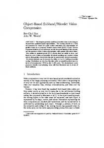
Figure 5 Echocardiographic images compressed with wavelet compression at moderate compression rates using a 2D, 3D or 4D approach: Using more dimensions improves compression ratios without loosing image quality
6. EXPERIMENTAL RESULTS To test the proposed compression strategy, we compressed 4D (= dynamic 3D) echocardiographic images. The size of a data hypercube was 2402161818 for x,y,z,t, with 256 gray levels, accounting for a storage size of 16 MB when using 1 byte/pixel. When using 8 bytes floating point accuracy for the wavelet algorithm, this dataset containing only one single heartbeat fills up 128MB of RAM. Nevertheless, we were able to run the wavelet compression algorithm within 31 seconds (2D), 41 seconds (3D) and 51 seconds (4D) on a recent Notebook PC (Pentium 3; 500MHz). Four scales of wavelet decomposition were done. Aiming at visually similar image quality with compression in 2D, 3D and 4D using moderate compression rates, we found that exploitation of the data coherence in higher image dimensions allows significantly higher compression rates than is possible with 2D compression only (Table 2 and Figure 5).
Proc. SPIE Vol. 4478
Downloaded from SPIE Digital Library on 19 Oct 2011 to 128.178.48.127. Terms of Use: http://spiedl.org/terms
431
compression intensity
moderate
high
wavelet decomposition strategy 2D 3D 4D 2D 3D 4D
max error
average error
32 29 28 31 36 32
2.09 2.07 2.25 2.95 3.60 3.45
mean square error 11.78 11.80 13.73 23.52 34.80 32.60
image energy kept % 99.67 100.32 100.49 99.51 98.68 100.06
PSNR
compression ratio
37.42 37.41 36.75 34.42 32.71 33.00
28:1 42:1 97:1 95:1 468:1 1000:1
Compressed file length 0.572M 0.381M 0.165M 0.169M 0.034M 0.016M
Table 2 Comparison between compressed-decompressed images and original 4D ultrasound images using different compression strategies and different compression intensities
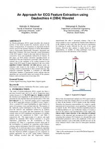
Aiming at very high compression ratios that retain prespecified image features of major medical importance (contractile function of the heart), we found that the higher dimensional approach allows much higher compression ratios up to 2000:1 (Table 2 and Figure 6). A two- to fourfold increase in compression ratio was generally observed per added dimension in the compression algorithm.
Figure 6 Compression of echocardiographic images with higher dimensional wavelets: Extremely high compression ratios of up to 2000:1 can be reached while diagnostic image information is retained.
432
Proc. SPIE Vol. 4478
Downloaded from SPIE Digital Library on 19 Oct 2011 to 128.178.48.127. Terms of Use: http://spiedl.org/terms
7. DISCUSSION Ultrasound images are typically strongly textured as each bright pixel corresponds in fact to an individual reflective surface in tissue, down to the resolution of the ultrasound signal, which is much less than 1mm. In addition, there is usually a significant degree of clutter noise, so that for image processing, ultrasonic data are especially difficult and smooth areas are almost inexistent. For these reasons, lossless compression methods yield typically low compression ratios of 2-3, which is mainly the result of the compression of the background not containing image information. In echocardiography, compression of no more than 20:1 (using the JPEG algorithm) has been accepted for clinical application (PSNR with JPEG with 16:1 compression on our dataset was 38). With dynamic 3D echocardiography, much higher compression is needed for this novel technology to be broadly applicable, especially, in the context of telemedicine. The strategy proposed in this paper is to extend the principles of 2D wavelet compression to higher dimensions, exploiting the inherent coherence of the data in the third spatial dimension and in time. We can thus document that a 3D and 4D wavelet compression algorithm is feasible, and is not too expensive computationally even on standard PCís (because wavelet algorithms can often be done in O(N) operations). The resulting image quality with higher compression ratios is similar to what is already accepted in cardiovascular imaging. When the requirements for image quality are limited to predefined diagnostic information (like contractile function of the heart, the single most important information of echo images), very high compression factors of up to 2000:1 can be achieved, so that the compressed images of a few kilobytes in size may be transferred even over a standard telephone line within seconds.
8. CONCLUSIONS We conclude that higher-dimensional wavelet compression in 3 and 4 dimensions is feasible and computationally not too expensive. By exploitation of data coherence in higher image dimensions, it allows much higher data compression rates than a comparable 2D approach while retaining image quality. The proven applicability of this approach to multidimensional medical imaging thus has important implications in image storage and transmission and, specifically, for the emerging fields of dynamic 3-dimensional imaging and telemedicine.
ACKNOWLEDGMENTS This project was supported by grants from the Swiss National Foundation for Research and the Swiss Heart Foundation.
REFERENCES 1. Donna Ehler, James L. Vacek, Sharad Bansal, Manohar Gowda, Kit B. Powers, ìTransition to an All-Digital Echocardiography Laboratory: A Large, Multi-site Private Cardiology Practice Experienceî, J. Am. Soc. Echocardiogr, 13, pp. 1109-1116, 2000. 2. Gilbert Strang, Truong Nguyen. Wavelets and Filter Banks, p. 365-383,Wellesley-Cambridge Press, 1997. 3. Martin Boliek, Charilaos Christopoulos, Eric Majani, JPEG 2000 Part I Final Committee Draft Version 1.0, ISO/IEC JTC 1/SC 29/WG1 N1646R, 2000 4. Luo Jiebo, Wang Xiaohui, Chen Chang W.,Parker Kevin J., ìVolumetric medical image compression with threedimensional wavelet transform and octave zerotree codingî, Pro. SPIE, Vol. 2727, pp. 579-590,1996. 5. Alistair Moffat. Radford M. Neal, Ian H. Witten, ìArithmetic Coding Revisitedî, ACM Trans. on Information Systems. 16, pp. 256-294, 1998 6. Luo Lin, Wu Yun-Nan, Li Jin, Zhang Ya-Qin, ìCompression of concentric mosaic scenery with alignment and 3D wavelet transformî, Proc. SPIE, Vol. 3974, pp. 89-100, 2000.
Proc. SPIE Vol. 4478
Downloaded from SPIE Digital Library on 19 Oct 2011 to 128.178.48.127. Terms of Use: http://spiedl.org/terms
433