External Vision Systems (XVS) Proof-of-Concept Flight Test Evaluation
Kevin J. Shelton*, Steven P. Williams, Lynda J. Kramer, Jarvis (Trey) J. Arthur, Lawrence (Lance) Prinzel III, and Randall E. Bailey NASA Langley Research Center, Hampton, VA, USA 23681 ABSTRACT NASA’s Fundamental Aeronautics Program, High Speed Project is performing research, development, test and evaluation of flight deck and related technologies to support future low-boom, supersonic configurations (without forward-facing windows) by use of an eXternal Vision System (XVS). The challenge of XVS is to determine a combination of sensor and display technologies which can provide an equivalent level of safety and performance to that provided by forward-facing windows in today’s aircraft. This flight test was conducted with the goal of obtaining performance data on see-and-avoid and see-to-follow traffic using a proof-of-concept XVS design in actual flight conditions. Six data collection flights were flown in four traffic scenarios against two different sized participating traffic aircraft. This test utilized a 3x1 array of High Definition (HD) cameras, with a fixed forward field-of-view, mounted on NASA Langley’s UC-12 test aircraft. Test scenarios, with participating NASA aircraft serving as traffic, were presented to two evaluation pilots per flight – one using the proof-of-concept (POC) XVS and the other looking out the forward windows. The camera images were presented on the XVS display in the aft cabin with Head-Up Display (HUD)-like flight symbology overlaying the real-time imagery. The test generated XVS performance data, including comparisons to natural vision, and post-run subjective acceptability data were also collected. This paper discusses the flight test activities, its operational challenges, and summarizes the findings to date. Keywords: External Vision System, XVS, Enhanced Vision, Supersonics Research, High Speed Research, Low-Boom
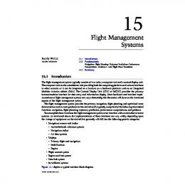
1. INTRODUCTION NASA’s High Speed Project in the Fundamental Aeronautics Program is addressing several research areas enabling the development of a low-boom/no-boom supersonic aircraft for flight over land. The new low-boom design requires a very long slender nose that prohibits effective forward-facing windows (Figure 1). The challenge then becomes the development of technologies which can provide an equivalent level of safety and performance to that provided by forward-facing windows in today’s aircraft.
Figure 1. NASA F-15 Test Aircraft / Gulfstream Quiet Spike [1], and Supersonic Airline concept
1.1 Background XVS is a combination of sensor and display technologies which may provide an equivalent level of safety and performance to that provided by forward-facing windows in today’s aircraft. Significant research was conducted under NASA’s High Speed Research (HSR) program during the 1990s on the design and development issues associated with an XVS for a conceptual High Speed Civil Transport (HSCT) aircraft [2]. What emerged from this work – which still *
[email protected]; phone 1 757 864-4470; fax 1 757 864-7793; www.nasa.gov
holds true today – is that the key challenge for an XVS design exists during VFR operations and when it is assumed that the flight crew has natural visibility (whether or not they may be operating on an Instrument Flight Rules (IFR) flight plan). Therefore, the driving XVS design standards emerge from the three tenets of Visual Flight Rules (VFR) operations which apply to all aircraft: “see-and-avoid”, “see-to-follow”, and “self-navigation” [3]. XVS is critical to the economic success of a supersonic aircraft with a nose boom, since the pilot’s lack of forward visibility would severely restrict aircraft operations and airspace usage especially when the weather is clear and visibility conditions are unrestricted – i.e., without an XVS, a low-boom supersonic aircraft cannot operate under Visual Flight Rules (VFR) since it would be unable “see-and-avoid” and “see-to-follow.” Previous work in this area investigated and verified the suitability of the display and vision system in basic aircraft operations including landing and low weather operations [4]. This flight test effort investigates issues with the integration of supersonic aircraft in the national airspace, for VFR/Visual Meteorological Conditions (VMC) operations, without need for special handling by air traffic control. In the Uninhabited Air Vehicle (UAV) sector, the “sense-and-avoid” technologies are actively being pursued and their work may be applicable [5]. These concepts are maturing and may be utilized in a support role towards meeting some of the XVS operational requirements, particularly the “see-and-avoid” requirement. 1.2 Objectives The primary objective of the flight test was to safely obtain exploratory data on see-and-avoid and see-to-follow capability using a proof-of-concept XVS in real-world flight conditions. This work is expected to lead to further efforts exploring the extent of the technology’s performance in a larger data set of real-world conditions.
2. METHODOLOGY 2.1 XVS POC Flight Test NASA Langley Research Center’s Beechcraft UC-12 aircraft was selected as the evaluation aircraft (Figure 2). Installed on the inside of the right windscreen were three High Definition (HD) cameras serving as the XVS sensors with a fixed forward field-of-view (FOV). The camera images were displayed on a matching FOV XVS monitor with flight symbology overlaying the real-time imagery. Two evaluation pilots flew on each flight, with Subject 1 in the cockpit right seat looking Out-the-Window (OTW) and Subject 2 at the XVS display in the cabin (Figure 2).
Figure 2. NASA UC-12 (NASA528) Test Aircraft and Cabin Layout
This configuration provided a simultaneous evaluation of traffic aircraft detection, identification, and threat assessment while using XVS compared to natural vision OTW in the same operational conditions. The evaluation pilot looking out the window was, in a sense, a ‘control’ for XVS pilot in same operating conditions. The primary metric was the measure of time for traffic detection between the two evaluation subject crew; visually out-the-window and with the XVS display. Additionally, several runs were conducted with the safety pilot simulating ATC traffic callouts directing the evaluation pilot’s scan. Other evaluations were conducted such as the cameras’ seams, clutter, latency, resolution, and the use of traffic cuing symbology. Custom hardware and software were developed that enabled the monitoring and recording of the evaluation pilots event marker buttons as well as the XVS display de-clutter switch. The flight test crew included a NASA Safety Pilot who was the pilot in command at all times, two evaluation subjects, and one operator/researcher. Several demonstration flights included additional personnel as observers.
2.2 Flight Test Operations Each data collection sortie consisted of multiple see-and-avoid and see-to-follow traffic scenarios. At mid-flight, the evaluation pilots swapped positions and roles. The evaluation pilots flew on two sorties so that each evaluation pilot observed two different size traffic (medium and small) aircraft at each observer location (OTW, XVS). Serving as the small traffic was the NASA Langley’s Cessna 206 and the Cirrus SR-22 shown in Figure 3. Acting as a medium-sized traffic aircraft was NASA Langley’s B200 King Air shown in Figure 4.
Figure 3: NASA Langley's Cessna 206 (NASA 504) and Cirrus SR-22 (NASA 501), Small Traffic Aircraft
Figure 4: NASA Langley’s B200 King Air, Medium Traffic Aircraft NASA 529
2.3 Operating Location All test flights originated and terminated at NASA Langley (KLFI) airfield. The evaluation flight testing operations were conducted in south eastern Virginia in the vicinity of and at Wakefield Municipal Airport (KAKQ). The participating traffic aircraft departed before the evaluation aircraft and joined up at the test operating area. The see-andavoid operations occurred over a long straight section of railway southeast of KAKQ (Figure 5). The see-to-follow operations were conducted at the nearby Wakefield airport.
Figure 5. Operating Location
2.4 XVS Proof-of-Concept Instrumentation A 3x1 array of Iconix Studio 2k HD cameras were arranged in portrait mode for a resulting FOV of 51ᵒ wide by 30ᵒ high with a pixel density of 63 pixels per deg. The minimal design objective of Snellen visual acuity was achieved and laboratory testing demonstrated the end-to-end system acuity was better than 20/20. Each of the cameras had a resolution of 1080x1920 for a total of 3240x1920 pixels. Each synchronized camera channel operates at 60 frames per second and was mixed (Figure 6) with computer generated symbology and displayed on the XVS display which consisted of 3-tiled LCD panels. The LCD panel pixel density and arrangement mirrored the camera pixel density and FOV to create a conformal display.
Figure 6. XVS Hardware Block Diagram, Display Design Eye Reference
The XVS display was mounted mid-cabin with a 25” design eye reference point to achieve the same field-of-view as the cameras. There was no overlap of the camera FOVs (Figure 7, right photo).
Figure 7. XVS Cameras and Display Installation
The small size of the Iconix camera heads enabled them to be mounted at the top of the windscreen on the right side. (Figure 7, left photo)
Figure 8. XVS Triple Display
The symbology of the XVS System (Figure 8) utilized in the flight test included typical HUD elements such as: horizon line with heading indications, pitch ladder with boresight reference, airspeed tape, altitude tape, and heading compass. A traffic designator box, using Automatic Dependent Surveillance-Broadcast (ADS-B), was also drawn based upon experimental condition. 2.5 Evaluation Pilots Volunteers were recruited to serve as Evaluation Pilots (EP). The evaluation pilot pool included civil servants and Department of Defense pilots. Six EPs participated in the flight evaluations. Two were USAF and the rest were civilian and represented a mix of operational and flight experience. The EPs had an average of 1250 flying hours and 17 years of experience. All EPs had current medical certificates and a minimum of 20/20 corrected vision. 2.6 Training All evaluation pilots were given a pre-flight briefing which covered the following topics: Experiment Background, Project plan, Test Objectives, Schedule, Operations Summary, XVS Operations, Test Conduct & Crew Procedures, and Question & Answer. The evaluation pilots were briefed on their task, which consisted of 4 parts: 1) detection of traffic, 2) identification of traffic, 3) recognition if the traffic poses a hazard, and 4) avoidance. At the end of each data trial, pilots were given questionnaires regarding tasks and their workload. 2.7 Evaluation Pilot Tasks/Actions: The evaluation pilot’s main task was to visually acquire traffic from their given position (OTW or the XVS). Once acquired, the pilot would press an event marker button and point out the traffic. The event marker button press is recorded with a time stamp in the data. 2.8 XVS See-and-Avoid Procedures The scenarios were designed such that the pilot could only detect traffic via their given position. The scenarios were also designed so the traffic aircraft would be first-detected in the forward view quadrant, within the FOV of the XVS. At the beginning of the run, the evaluation pilots were instructed to begin the traffic scan task and press the event button when traffic was spotted. There were two different see-and-avoid scenarios selected from a number of possible scenarios utilized in previous flight tests. Two nose-to-nose scenarios were chosen as the most difficult in detecting traffic aircraft, as the traffic aircraft is simply expanding and not translating in the FOV [4]. ADS-B data was provided to the Safety Pilot for scenario set-up and safety-of-flight. A temporary cardboard vision restriction device was placed such that the OTW evaluation pilot could not see the ADS-B display.
Scenario 1A - See-and-Avoid, Nose-to-nose, Horizontal Offset This nose-to-nose scenario had the evaluation aircraft and traffic aircraft in long closed loop patterns, with close but nonconflicting ground tracks shown in Figure 9. Both the evaluation and traffic aircraft were at the same altitude. The traffic aircraft approached from the southeast and maintained a path parallel and East of the railway tracks.
Figure 9. Scenario 1A – See-and-Avoid, Nose-to-Nose Horizontal Offset (not to scale)
The evaluation aircraft approached from the Northwest and maintained a path parallel and West of the railway tracks. The lateral separation between the aircraft paths was 1000 feet (ft.) or less, but not less than 500 ft. Ground reference points (railway tracks) and electronic navigational displays with custom waypoints were used for coordination. Aircraft depicted in Figure 9 are in the start position. Note that Figure 9 is not to scale, thus the oncoming traffic appeared in the 11 to 12 o’clock position, expanding and not translating in the field of view. Scenario 1B - See-and-avoid, Vertical Offset, Traffic Below This nose-to-nose scenario had laterally overlapping ground tracks but with a vertical separation. The traffic aircraft, simulating a departure, was climbing towards the test aircraft and appears as a stationary expanding traffic in the ground clutter. The initial start configuration is shown in Figure 10, with the aircraft vertically separated by approximately 3500 ft. The evaluation aircraft was in level flight at approximately 4500 ft. during the entire scenario. The traffic aircraft began to climb from approximately 1000 ft., simulating a departure and then leveled at an altitude 500 ft. below the evaluation aircraft. The aircraft climb rate was approximately 1000 ft. /min.
Figure 10. Scenario 1B – See-and-Avoid, Vertical Offset, Plan and Profile View (not to scale)
2.9 XVS See-to-Follow Procedures There were two different see-to-follow scenarios selected for typical traffic interaction in the terminal area: an in-trail to a single runway and parallel runway scenarios. The EPs were instructed to scan for traffic and press the event button when the traffic was acquired or reacquired due to maneuvering. Scenario 2A - See-to-Follow, In-Trail; Following Traffic Aircraft This scenario had the evaluation aircraft follow the traffic aircraft around an extended visual landing pattern. Approaches were flown at a constant altitude, as landings were not required. The evaluation aircraft’s pattern altitude was 1500 ft AGL and the traffic aircraft was 1000 ft AGL. The evaluation aircraft followed as #2 in-trail at a minimum distance of ¼ to ½ statute miles, shown in Figure 11.
Figure 11. Scenario 2A – See-to-Follow, In-Trail, Plan View
Scenario 2B - See-to-Follow, In-Trail; Following Traffic Aircraft This scenario simulated simultaneous parallel runway approaches, with the traffic aircraft in the lead and approaching a landing to a designated ground reference acting as a virtual runway. As in the previous scenario, approaches were flown at a constant altitude, and the minimum slant distance between aircraft was ¼ to ½ statute miles, shown in Figure 3 at three different points of time (T1-T3).
Figure 12. Scenario 2B – See-to-Follow, In-Trail, Plan View
2.10 Post-Run After each run the evaluation pilots were given the following questionnaire to assess the run and assign a workload rating. Post-run question (1A) asked the pilots to rate the ease in detecting traffic within the visual scene marking the Likert scale (Figure 13) from 1 (Very Hard) to 7 (Very Easy). Similarly, post-run question (1B) asked the pilots to rate the ease in identifying traffic within the visual scene using the same scale. Very Hard
Hard
1
2
Somewhat Hard
3
Neutral
Somewhat Easy
Easy
Very Easy
4
5
6
7
Figure 13. Ease of Detecting and Identification Likert Scale
Post-run question 2 asked the pilots to provide ratings for the statement “I had sufficient time to assess and react to the traffic I detected” on a Likert scale from 1 (Strongly Agree) to 7 (Strongly Disagree). Finally, the Air Force Flight Test Center (AFFTC) Pilot Workload Estimate was admitted and the evaluation pilots rated their workload on the following scale: 1 – Nothing to Do; No System Demands 2 – Light Activity; Minimum Demands 3 – Moderate Activity; Easily Managed; Considerable Spare Time 4 – Busy; Challenging But Manageable; Adequate Time Available 5 – Very Busy; Demanding To Manage; Barely Enough Time 6 – Extremely Busy; Very Difficult; Non-Essential Tasks Postponed 7 – Overloaded; System Unmanageable; Important Tasks Undone 2.11 Post-flight During the post-flight debriefing, unstructured free-form pilot comments were solicited and a post-test questionnaire was administered. The EPs were asked to provide an assessment of their display preference and their perceived safety (using a Likert scale) during operations for the tasks that they just completed flying.
3. RESULTS 3.1 Flight Summary Table 1 is a summary of the six XVS data collection flights. There were ten (10) flights in total including an instrument check flight and three demonstration flights. All flight time totaled approximately 20 hours with the data collection flights comprising approximately 12 hours. Table 1. Flight Summary
Flight No
EP#
EP#
Traffic Aircraft
1 2 3 4 5 6
1 4 4 1 5 5
2 3 3 2 6 6
Small Small Medium Medium Small Medium
Estimated Visibility Conditions Up and Away 5 mi Haze 4 mi Haze 15 mi Haze ~10 mi Haze 7 mi Haze