Using 3Dlnfomation Extracting of AnalYsis Spatio-Temporal AeriallmageSequences GuoqingZhou, JoergAlbertz,and Klaus Gwinner
Abstract
Repeated texturc appeannce. Some patterns, such as walls or house groups in residential regions,appearrepeatedly.Thus, it is dihcuit to find the matchlng corresponding points when using traditional stereomatching schemes. Depih discontinuifies. Almost all buildings stand above the suirounding terrain, which gives rise to depth discontinuities. Such features cause three problems in 3D information extraction. First, it is difficult to rise an additional smoothing constraint in the stereomatching process.Second,occlusions occur in the image planes.If the occluded regionscannot be recognized corre-tly, the gray information will disrupJ nor"matching, mi;le;d matclring. Third. the depth o. mal cause an abrupt change in the apparent discontinues often"n"n surface brightness due to shadow.
To overcome depth discontinuities and occlusion problems in three-dimensional(so) surface infotmation extraction using traditional stereophotogrammetricmatching, a new approa.ch called spatio-temporal analysis of aeriol image sequencesis propotid. In the proposed method, a set of spotio-temporal 'iota aotois first'formed from a sfficiently dense-sequence,of moving alo.nga^straight-line path' images taken by a "ameia solid-of data is sliced spatio-tempotol sei of Secind, the along a temporal dimension into epipolat-plane lmages (spti, and fbaturesin these slices are exttacted and described.fiitally, three-dimensional coordinates in a ground coordinate syite^ ate computed for the f-eaturesin the EPIs' Obviously, none of the traditionalapproaches has so far This method is faiily radically diff-etentfrom^traditional twoablt to solve the above mentioned problems successbeen view stereophoiogrammetric matihing; therefote, we discuss fuIlv, For example: (1) the correlation coefficient approach in detail th'e estihation accuracy' eftor resources, and sensi- *"n oro"..o*e iatPe g,ravdifferences, but it cannot resolve tivities to occlusion and depth discontinuities. The expetino.r-litt""t gray-valuJcomponents,qnd it is sensitiveto geomental rcsultsfrom three tist fields in Betlin-' Germ.a-nysho^w metric dist6rtion causedbv depth discontinuities; (z) multithat the method is a useful tool fot solving the ptoblems of ple-point least-squaresmaiching (rsu) can theoretically deal depth discontinuities an-d occlusion with which photogram' with repeated teitures and poor textures; however, because mit ittt have been wrestling for a decade. the algorithm depends on the constraint of surface continuitv. minv difficulties are encountered when depth discontilntroduction nniti"t exist; and (3) feature-basedmatching algorithms can Extractingthree-dimensional(an) surfaceinformation from achieve a satisfactory effect relative to area-base4matching large-scal"eaerial images is an important research field in in handling large griy differences, but their applications are oh6tosrammetrv,computer vision, and robot vision navigaU-"yttre eTfeitin"ness of the feature detectors and by restricted tion. du". the list decadeof photogrammetricdevelopment, 3D data interpolation error (for example, only some sparse a laree number of efforts have been pursued' However' beare pioduced). heights "In caus6the scenesmay be very complex and diverse' many expuper, *e Proposea spotio-temporalanalysi.s this isting algorithms, suth as traditionll stereo mat-ching,have to extract eD surface information from aerial -image technique Therefore, sho#n a"ninability to cope with such scenes-. ,"qrr.tt"r. The method was originally presentedby Bolles when two-view st-ereophbtogrammetricmatching is used for utt& Buk.. (1s8sa),Bolles and B-aker(rsasbJ, Baker ef o1' 3l information extract-ion.t[e following problems may occur: (1980),and Baker et al. (1987) for the analysis of motion im. Largegray-value differences between -cone sp on ding p oints' t"qn"tt""s. Their initial experimental.environment fully "g" s"#uie i nigftt *ditta havecapturedaerialimages-from .ti"t ttti four constraint conditibns listed in the next section' gray varying."-J.^ positions(a largebaselinelength),-th-e (1987)extended the analysis to arbitrary motions d^ifferences' Bolles ef d1. Iarge. iorrespondingpoints-show values.-between using projective duality in space.Their generalizationsare Moreover, it is very difficult to model the gray dlllerences- lr on (i)itre generalizationof their technique for varying viewtraditional stereo matching schemes are employed' rt woulcl ine'directi6ns.including variation over time; (2) the-provi- . be difficult to get accurate depth information flom the variconnectivity information for buildriJ" of three-dimension"al ous scenes. ine cohet"nt spatial descriptions of observedobjects,;and (3) a Poor texture appearance. In some homogeneous Sray ereas'.sucn gn information is una sequentialimplementation, allowing initiation and refineas water, house-tops, Srassy, etc., exhacted elements' matching points the as when using reliable meni of scenefiature estimateswhile the sensoris in motion (Bakerand Bolles,1988;Baker and Bolles,1989)'This paper vil & Environmental Eneineerinsand Geodelic Science.The Ohio State Univer.iti. +zo HYtchcockHaIl' 2070 Neil Avenue, Columbus, OH +sbn-Pz s (
[email protected])' of Photo). Albertz aoa f. Gwinner are with the Department Berlin, of University Technijal Cartography, grammetryand des 17 Juni 155,-Sekr.EBg,D-10623Berlin, Germany' 5t "m" SEI{5Ii{G & REMOTE ENGINEERING PHOTOGRAMMETRIC
Photogrammetric Engineering & Remote Sensing, Vol. 6s, No. 7, JulY 1999,PP. 823-832' oo99-1112/ 99/650 7-B23$ 3.00/0 Society for Photogrammetry American 1999 @ and Remote Sensing
Iuly t999
a23
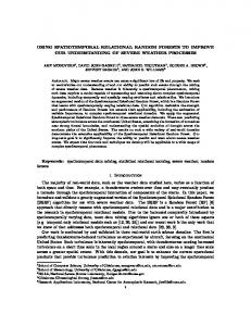
Figure1. Constructionof a spatio-temporal data ser.
describesthe acuracy to be reached,and the ability to accomodate,occlusiory -u"g depth discounities when the tLchnique is ppli94 in aerial photogrammetry.Three test fields were estabIished built in Berlin, Germany. The experimental results show that the technique is able to solve some of the problems which conventional photogrammetryis not able to solve.
E[ipJdar hnes
Pilnciple ofTemporal andSpatial Analysis
The original method was based on th-efollowing four conditions: o The camera'smovementis restrictedto a straightlinear path, o Imagecaptureis rapid enoughwith respectto camera,s movementand scenescaleto ensurethat the dataare temoo_ rally continuous, o Thevelocityof the camera's movementis a constant,and . The camera'spositionand attitudeat eachimagingsite are Theoretically,if a cameramounted on an airborne platform flies along,a straight line path (flight course),and ihe camera'soptical axis is orthogonal to the direction of motion, this operational condition meets the above constraint conditions. The impact of irregular real flight movements will be addressedin the Error Analysis sec"tion. The meaning of-the second condition is that the image sequencescaptured by the cameraare so close that none-of
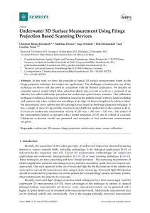
Figure2. Spatio-temporal solid of data.
July 1999
Figure3. Construction of epipolarplaneimages (EPrs).
the image featuresmoves more than a pixel or so. This sampling frequency guaranteescontinuity in the temporal domain that is similar to continuity in ihe spatial domain (Figure 1). Thus, an edge of an object in one image appears temporally adjacent to its occurrence in the folloiadng imug". This temporal continuity makes it possible to construct a cube of data in which time is the third dimension and conti_ nuity is maintained over all three dimensions. This solid of data is referred to as spo-fio-tempora)dafa (Figure Z). Figure 3 shows three individual imagei used to foim"ttre solid "of data. Typ^ically,100 or more imag"r are used, making the tra_ jectory of a point, such as P, follow a continuous patfi. With the first condition, supposethat there is a simple motion in which a cameramoveJ from left to right, with its optical axis orthogonal to its direction of motioi. For this lVle.of motion, the epipolar plane for a point p is the same tor all camerapositions. We call this plane an epipolar plane of the point P for the whole rnotion. Ii the velocity of th'e c-amerais a constant (the fourth condition), the trijectories in the epipolar planes images (EpIs)are straight tlnes. f,lgure 3 illustrates the construction of the epipolaiplane imag6s. . Tlu projection of P onto the epipolar lines movei from the right to the left as the cameru itore, from the left to the right. The velocity of this movement along the epipolar line is a function of P's distance from the line-throrrgiih" lurm centers,The closer it is, the faster it moves. The"refore,a ver_ tical slice of the spatio-temporalsolid of data contains all the e_pipolarlines associatedwilh one epipolar plane. If we slice the spatio-temporaldata along the temporal dimension, a new."image^plane,"which is called the epipolar_planeim_ age (arl) is formed (Figure 3). coordinates can be computed from the fourth !f, y, condition,")We first derive an equation for the traiectorv of a PHOTOGRAMMETRIC ENGINEERIT{G & REMOTESENSII{G
B:s'At where zif : (t, - t,). From similar triangles (Figure 5), we have u1
xo
hD Ll2
B*xo
(3)
hD
in the EPl. Figure4. Trajectory
scenepoint in the npI constructedfrom a motion, and then explain liow to compute the (x, y, z) coordinatesof such a point' h'ieure+ is a diagr-amof a traiectory in an EPiderived from the left-to-right motion illustrated in Figure 5. The image row at f' in Figure 4 correspondsto the epipolar line f in FiSur-eS' Similarlv] the image r-ow at t, conespondsto the epipolar line ,lr' (Rememberthit the EPIii constructedby extracting one line tom each image taken by cameraas it moves along the straight line from cl Io"cz.Becauie the images61slaken very close tosether,ther'ewould be severalimagestaken between c' and c-r' i{o*".r"r, to simplify the diagram,none of them is shown') The Doint (u,, f,) in the ilt correspondsto the point (u,, v,) in the imase taken bv the cameraa[ time f' and position c'' Thus, as the iamera moves from crto c, in the time interval I' to f, the scenepoint moves in the EPIftom (u', JJ to (u,, t,). The intent of above section is to characterizethe shape of this trajectory.The following describeshow-to comprrte the ^ three-dimensionalcoordinateswhen given the focal length of the cameraand the camera'svelocity. In our analysiswe define a right-hald coordinate system that is centeredon the initial position of the camera' Given the speedof the camera,s, which is assumedto be a constant,the distanceB from c1 to c2 can be computed as (seeFigure 5)
where u, and u, have been converted from pixel values into distancesin the image plane, h is the distance from the projected lens center tolhe epipolar line in the image plane, x, is the x-coordinate of P in the scenecoordinate system,and D is the distance from P to the line through the lens centets. Becauseh is the hypotenuseof a right triangle,it can be comPuted as follows: (4)
h = \rp + v?
where / is the focal length of the camera.From Equations 2 and 3, we get h(Br x') : DD A u : ( u , - u' r, ')D *
:It
(5)
Eouation 5 shows that Au is a linear function of B, while B is alio a linear function of dt. Thus, /f is linearly related to 4f' This means that all trajectoriesin the EPIsare straight lines in the constrainedstraight-linemotion. The (x, y, z) coordiiratesof P can be computed from u,, u, and/. From Equation 5, we define DB hat
(6)
which representsthe slope of the trajectory computed in terms of ih" dittu.t"" traveled by the camera (B as opposed to AfJ and the distance which the point moves along the epipolar line. From similar triangles,we have
= ,1,,,1,,.20f, (*'y',) Equation 7 may be rewritten as (x, y, z) : (mu,, mv,, mf).
(7) (B)
If the first cameraposition c1,on an observedtraiectory,is different from the iamera position cn,defining a global camera coordinate system,the x coordinate has to be adiustedby the distance traveled from co to c'. Thus, (9) ((t' - fo)s* mu', mv', mf) "): where to is the time of the first image and s is the camera's speed.ihis conection is equivalent to computing the interc'eptx of the traiectory,which is the first camera'sposition' Tlierefore,the (x, y, zi coordinatesofthe points can be easily computed from the slopes and intercepts of the traiectories' (*, y,
Analysis ofSpatioTemporal Expeilments
for computing3D Figure5. Geometricconfiguration coordinates.
SENSING & REMOTE ENGINEERING PI{OTOGRAMMETRIC
Thiee test fields in the region of Berlin (Berlin city, Schonefeld, and WerderJwere uJed to test this technical application in aerial photogrammetry'In October1995, the image s-equencesfor the.-threeexperimentalfields were capturedusing a video cameramounted on a Cessna2O7T ilying platform' Details of the imaging parametersare listed in Table 1' The original Jata"wererecorded on a video cassette,and the digital iirage sequenceswere obtained by resampling-ata freque"ncyof rd frames/second.For further analysis,yu.d": vel6ped software to implement the programs,which include the following stePs: Iuly I 999
825
TqeLE1.
lvncrnc Flrcnr PARAMETERS.
Name
Parameters
Platform Flight height Focal Length Flight velocity Cameratype Scale
Cessna2077 about 800 m 35 mm 100 Knots S-VHS,PanasonicVideorecorder 1.:25OO
Figure6. The first originalimage.
o The third step applies an edge detectorto detect .,edge-like,, featuresin the npts.We use the zero-crossingoperatoi to detect the edges(seeFigure 9), whose originallrnaee is shown in Figure B. o The fourth step fits Iinear segmentsto the edges.It is divided into two-passes.The first pass partitions the edgesat sharp cornersby analyzing the curvaturesof the edged.The second pass applies a regressionalgorithm to recursiiely partition the smooth_segments_into continuous straight line^segments. Figure 10 shows the linear segmentsderived from th6 edges in Figureg. o The fifth step builds a description of the line segmentsthat aligns together those that are collinear. The line*seementsare used to identify sets of lines that belong to the samlefeature, Figure 11 shows the edge feature descriptionsfor Figure 10 that arelinked by bridging gaps causedby occlusion"sor other effects(for example,lines broken bv the edee detection operator). o The sixth step computesthe (x, y, z) coordinatesof the world features corresponding to the EpI features. The world coordi_ nates are uniquely determined by the slope and intercept of the trajectoriesin spt. Figure 12a shows t-he(x, y, z) "ooidi_ nates for world featuresmarked with black points inside the white rectanglein Figure 7. . The seventhitep link x-y-z points betweenEprto obtain structure information. Figure 12b iilustrates the structure in_ formation for world features marked with the black noints in_ side the white rectanglein Figure 7. For the first experimental field, we concentrated on estimating the accuracy of the (5 y, z) coordinates for the points on a profile. The eleven profile points are marked with^black points inside the white rectangle in Figure 7, The profile cor_ responding the 500th Epr (Figure a) incfudes houses, ground, and shadows (see Figure 7). The (x, y, z) coordinates"of the profile points gre illustrated in Figuie 1.2. The experimental result shows that the heights of two houses are clearly distin_ guished from the ground surface.
Figure8. The 500th epipolar-plane image.
Figure9. The detectededgesfor the 500th Ept.
Figure7. The imageof noise removaland an Eptcon_ structedfrom 60 images.
o The.first st€p-consists of noise removal algorithm. The origi_ nal image is depicted in Figure 6, while F*isure Z shows tlie pre-processing image after nojse removal. . The second step generates EpIs flom the spatio_temporal solid of data. Figure 8 illustrates the b00rh rpt constructei from a sequence of 60 images.
826
luly 1999
Figure10. Fromedgesto line segments.
Figure11. Linesegmentdescriptions.
PHOTOGRAMMETRIC ENGINEERING & REMOTE SE]IISII{G
E 165160 155 150 L45 140 135 130 125 L20
E c
-\)
{
tttr-
700 0
d
q
1 65 16 B 15 o 15 L4 l4 13 13 c t2 t2
arr"ot
700 0
YuH"'",Truu,.", 4
to the blackpointsin Figure7. FigureL2. The of (x, y, z) coordinatesof world featurescorresponding
In order to have an evaluation of the accuracyof the entire sl surface,the DEMis generatedby a simple nearestheight interpolation algorithm from sparse(x,,y,.z).cootdi'nat6s extracied using the spatio-temporalanalysis (seeFigure 1Fl Rv examininsFisure is. we believethat the DEMdata
of Figure7. The blackpointsindiFigure13. Subsection cale the extractedinformationusingEPIanalysisat a 5pixeleetinterval.
L80 L70 1-6 0 n
t
For the second experimental field, the imaging parameters are the same as for the fi-rsttest field. In the scenean obvious landmark - a chimney - is chosen to test the sensitivity to occlusion and depth discontinuities. The black points depictedinside the white rectangleof Figure 16 are ihe extractedprofile features,whose correspondingEPIis shown in Figure 18 [the 22othEPr).The (x, y, z) coordinates for these woild features and their structure information are illustrated in Figure 19. A magnified view of the chiTney top shows the l6cating accuracy of the chimney, as illustrited in Figure L7. The DEMdata generatedfrom sparsecoordinates (i, y, z) are illustrated in Figure 20. By examining . Fis,ure z0 and the 220'hnrt (Figure 1B), as well as the (x, y, z) co"ordinates(Figure 19), we find that (f) the,estimationprecision for (x, y) ii apparently better than that for z; (2) rhe technique cin effeclively deal with occlusionsbecausethe trajectoiies of the occluded objectsare broken temporally [seethe 220thEPIin Figure 1B); (3) the technique easily-handles depth discontinuilies becauseit does not need to determine tlie magnitude of horizontal parallaxes,and gD coordinatesdan be obtained from the trajectoriesof the features in nrrs directly; and (+) the DEMdata are relatively rough in the scene,-butthe higher buildings can be reflected correctly.
50
140 L30 120 1
10 00
*
Figure1-4.(x, y, z) coordinatesof the house and the shadow.
Figure 13 is a subsectionof Figure 7-,in which a house is coniiined. The black points indicate the information extracted at a 5-pixel gpt interval. The (x, y, z) coordinatesfor the shadowsand the housesare shown in Flgure 14, in which the dotted lines are (", y, z) coordinatesof a shadow' By examining Figure 14, we find that the shadow and ground have different heights. SENSING & REMOIE ENGINEERING PHOTOGRAMMETRIC
field. Figure15. DEMdata for the first experimental
luly 1999
427
simple nearest-heightinterpolation algorithm from sparse(x, y, z) coordinates.By examining the experimental results (Figures 22 and 23), we find that the z coordinatesof the road still show a relatively large variance, Moreover, the DEMdata are relatively wild in the scene.
200 F 790 180 170 160 a 150 o 1 4 0 tr 130 o L20
148
c o
c
Figure16. The first imagein the secondexperimental field.
,-t"O'
'700 00
FigureL9. The (X y, z) coordinatesand the structureinformationcorresponding to the profilemarkedby black pointsin Figure16.
Figure20. DEMdata for the secondexperimental field. FigureL7. Magnifiedimageof chimneywith locatedfeature points.
Figure18. The 22Othepipolar-plane image.
The third experimental field is a more complex scene. involving trees,bushes,forest, houses,and roads. Many houses.arenot easily identified becauseof the lower iriage resolution. A road is chosento evaluatethe accuracvof t*he spatio-temporalanalysis.The black points inside u #hit".e"_ tangle in Figure 21 are the world fealures extracted by using the_spatio-temporalanalysis at a S-pixel npI interval. th" ordinates(x_,y, z) of the road are illustrated in Figure 22. "o"Similarly, the DEM,visualized in Figure 23, is gerieratedby a 828
luly 1999
Figure21,.Thirdexperimentalfield and the extracted road'sfeaturepointsusingEptsat a S-pixelEptinterval.
PHOTOGRAMMETRIC ETTIGINEERING & REMOTE SENSIilG
140: E 135 13
E t' o o
120
C
o d
3
135
E
130
t
LZ5
140;
r,yl
coordilrt!5
fot rord
-c
\il,
I
\ VV nrVn-ll
'V I
E o
725
-"s'
a 0
120
?00 0
c
.700 00
Il;**r",,,..,
Figure22, The (x, y, z) coordinatesand the structureinformationfor the road.
a hundred images,and line segmentsare describedby gPplying a regressionalgorithm associatedwith gross error elimina-ti.rgtechnique. Figure 25 illustrates our compensation principle employed in our program. Deviation from the ideal cameta path in the vettical P.fone,. When the'optical axis of the camera (the cameraviewing direction) is not orthogonalto the direction of motion (Figure zzl,thle error can be modeled as follows (Wang' 19BG):
6.: -
dsinesine r -
field. Figure23. DEMdata for the third experimental
(10)
-g sin 0 Tsin
where 6. : r - ro is a radius difference (seeFigure 27)' When the angle g is very small, Equation 10 can be approximated as (11)
a,-;sinssing.
EnotAnalysis
It should Le noted that the operational conditions of our airborne experiment ate much more complicated than we had ,,rppot"d. The real operation of the camerashows considerabid deviations from an ideal linear movement' Atmospheric turbulence, flight vibmtion, and other influences result in a rather irregutai llgtrt course' This is why the trajectories of the features in upls are not straight lines. On the other hand, viewing direction randomly varies due-to changes th, "u*.r"', in tne night attitudJ parameters,inclu-dingthe roll, pitch' yu*""ttgles. Thui, it is n-ot possible to guarantee that the "rrd aeriai imagJsequencesexactly meet the four constraints'In ihe reiolution of the images capturedby the video "aaitio", CCDcamerais not very high' In the second-resampling,some information may be lost again. Therefore,these various error sources cause rither large errors in the world coordinates' Here we analyze severalkinds of error paradigms' Deviationfrcm the ideal cameta Path-in -the horizontal plane When the'cameradeviatesfrom the ideal path in the horizontal plane, that path is distorted (Figure 2a) and the trajectories fbr the features in the EPIsshow a "zigzag" shape' ttin,rt" 26 is an EPIhom the first experi.mentalfield' The ld"eesthat appear like narrow white bars in Figure 26 show iiigr^g" shape.If the deviation is restricted an"obvious follo* a stochasticprocess,the erfiniteian-ge a within "ttd by our proBram automatically berors can be compe'nsated th" trajecttries in the nprsire generated by more than "a"te SENSING & REMOTE ENGINEERING PHOTOGRAMMETRIC
-
ot mo1 yolon 1to1*lroyof o feofure .6fu$ection -{Vrewtrg dtection |ine Epipolor
Figure24. Trajectorydeviationand yaw angle of the camera.
\A
^
imoge Epipolor
D' P\r
- sconline * Reoledge - Delected edge
\B'
u''
t fuo F, ,=,
r'fun H', 'q"
tr \
\n'
(i'\
rt r
rH'
Figure25. Errorcompensationalgorithm.
luly tqss
a29
Edge location error We can determine the (x, y, z) etror values causedby the edge location error in terms of error propagation laws. The mean error for (x, y, z) can be given by (from Equation 9) Figure26. The trajectoriesof featuresand deviationsof the camerapath in the horizontalplane.
Q-:
AxAu
m a D , , , : --:- rP.. : s ' s l o p e ' @ , , , ( w h e n f : f r )
@"=r.slope.rD,,
(12)
Q.:s.slope.f
B
Q*r .,'
Equation 12 shows that the mean errors of the coordinates (x, y, z) are a linear function of u and y, and the scale factor is the velocity of the camera'smovement. If s = 1,70(m/second),and @,,,: A", : one pixel : 0.001 m, i.e., the trajectory of a feature shifts one pixel along the u and v directions in the EpI,respectively,and the slopJ : 1 (45') (Figure 29). When the slope value of the trajectory remains constant,we have
Figure27. Camerapath deviationin the verticalplane.
In Equation 1.1,when @equals 0o or 180o,4 = r - ru reaches a maximum value, i.e., the deviation is greatest;when f equals 90oor 270o,the deviation is smallest.Moreover, the positive and negativesigns changerandomly with angles varying from 0o to 360'. Thus, the deviation can still be considered as a stochasticprocess.This kind of error can also be compensatedautomatically by our program with the same compensationprincipal. However, if the camera'sviewing direction deviatesat a fixed angle relative to the direction of motion, which means that the deviation is not a stochasticDrocess.the traiectories of the featuresin Eptsare simple hypbrbolas(Bakerand Bolles, 1988;Bakerand Bolles,19Bg).If the angle of the camera's viewing direction relative to the direction of motion shows systemic errors, it is impossible to partition the scene into a fixed set of planes,which in turn means that it is not possible to construct EpIsfor such a motion. In these two cases,our program is not able to compensatethe errors. The velocity of the camera'smovement is not a constant We can derive the traiectoriesof the featuresin EpIs.The theoreticalanalysis (seeAppendix A) shows that the trajectories of featuresin EPIsare composedof severalline segments with v_ariousslopes rather than being simple straight lines. If the velocity of the camera'smovement vaiies only occasionally during the entire movement process,our program can automatically compensatefor such an enor by employing a blunder eliminationalgorithm:however,if th"evelbciiy d"uring the entire movement processvaries continuously, our program loses this kind of compensationcapability.-On the other hand, if the error cannot be controlled effectlvely, it will reach rather large (x, y, z) deviations becauseit cin changethe slope of the trajectory (seeAppendix A). Figure 28 illustrates the true trajectoriesof the feitures in the spI hom the third experimentalfield. The sampling frequency cannot guarantee temporal continuity This means that an edge of an object in an image does not appear temporally adjacent to its following images.Thus, the traiectory of a feature consistsof several line segments(broken lines) rather than an entire straight line. Our program can bridge the gap automatically. Figure 28 illustrateJ the fact that the low sampling frequency cannot guaranteecontinuity in the spatial domain (severalbroken line segments). 83O
Iuly tggs
Q,:
1 7 O. s l o p e :
0.17(m)
(13a)
tD, = 1,7O. slope : 0.17(m)
(13b)
@.=1,7O,slope,f
( 1 3c )
Equations 13 show that, if the trajectory of a feature shifts one pixel along the u and y axes in the Ept,the x and y coordinates in the world can reach a 0,17-meterdeviation, whereasthe zcoordinate does not change. In the same way, if the slope of the trajectory of a feature deviates one pixel (this is in fact quite possible), the error in the (x, y, ?) coordinatescan reach a rather large deviation. Therefore,high accuracy edge location is significant.
Further Work Even though this technique shows that the (x, V, z) coordinates have errors, the precision of the (r y, z) coordinatesin the first experiment is still acceptable;the-secondexperimental results show that the technique is a very useful tool in overcoming depth discontinuitiei and occluiions. In order to improve the estimation precision of (x, y, z) coordinatesand develop this technique to a practical tool in photogrammetry, the above-listederror sourcesmust be reduced or eliminated bv the software automatically. The following efforts are necessary in the future: o FroryEqrrallott 9, the (x, y)-coordinates of oblectpointsdependon the interceptof the traiectories of the featuresin nPIs,and the z-coordinate of objectpointsdependson the slopesof the traiectories of the featuresin npis.If the coordi-
Figure28. Trajectoriesand varyingmovementvelocity, low frequencyresampling.
Epipolorlmoge
Epipolorircge
Detected
Detsted
Figure29. Detectedand reat edge. (a) The trajectorydeviates from ideal direction.(b) The trajectoryshifts along the uand yaxes.
PHOTOGRAMMETRIC EI{GINEERING & REMOTE SEI{SING
the EPIsare straight lines, only very similar data are processed.Thus, the approach is much simpler and more robust. Third, this teilinique involves the processingof a very lareenumber of imaqesacquiredby a moving camera'i'e" a gre"atdeal of redundint information is produced,which is i.ot used in the conventional stereophotogrammetricapbut is not reproach. Fourth, the approach is feature-based, 'stricted to point featrirbs.Linear featuresthat are perpendicular to the diirectionof motion can also be used' Fifth, spatill structures in the EPIsare much simpler than in the original, which means that they are easy to be interpreted and analyzed. ' By examining the describedEPIin Figure 31, which cor,"rporrd, to the oiiginal uet (Figure L8), we fi'rrd that the traiect'oriesof the occl"udedobjecti are temporally broken byFigure30. An Infiniteof slope of the trajectoryano 'other tralectories,which coirespond to the high obiects'This the z-coordinate. means that occlusions are quite apparent in the EPts'Thus' lh".u ut. many chances to detect them. We can theoretically prou" (t"" Appendix B) that, if an objecttemporally occludes l"Ltft.t oblect, the traiectoriescorrespondingto the occludine utd o..lrrd.d feature intersect in the EPI'Moreover' for ittt".t".tion, the feature with the smaller slope occludes ""Ztr ifr" o"" with the steeperslope. This means that the higher building occludesthe lower one' Addition-ally, the trajec.toFigure31. The relationshipbetweentrajectoriesand ocries of frigh.. buildings, which cause depth discontinuities' clusions,dePthdiscontinuities. can obviously be reflected in the gPIsbecauseof their steeper rfo"tt. As mLntioned above,the 3D coordinatesare directly oUtii""a from the trajectoriesof the high buildin-gsin the EpIswithout determining the values of horizontal parallaxes. natesat the points (u" f,) and (u., f,) in the npI,which corretpo"a to the points [u',-v'), (uu v") in the image taken by the itr"."fo.t, the approach"ismore robust in determining lhe at tim^ef' f, and positions c1, cz are equal' the slope u"a h.pttt continuities than is the traditional mul;;;l;tt."; "^"-"r" oi tt u itul".to.y is infinity (Figure 30) This meansthat the (two)-view matching' tiple --' -Ni"rr".th.less. (x. v. d coordinatesof world featurescorrespondingto the becausJthis is lust lhe first practical appJiiraiLctories in the EPIreach infinity' ln this case' we must anto aerial photogrammetry,-more-testtechnique of this cation For example,if the directions of a road ;-1y^ lt;; becaule the operationalconditions Particularly, "ut"f"Uy. ine lt of direction the u horlr" are approximatelyparallel-to"""a"a. path deviatesconsiderably carnera's reai the EPIs ;; ;;; complex, "rrd the traiectoriesfor the road and the house in the motion, image sequencesis distorted the different' Rectifying in fact one. are an ideaf ftom z-coordinates their but ate identical, combining withadiustment advance' in bunate thJ sequences impe.atin". Additionally, o Ceometricrectification of image ls out (or withJ known orientation parametersof the cameras' CpJ u"a image data to get the orie,ntationand attitude paramimoerative' This has been demonstratedby the analysisof ireters of the c"amerais firndamental to practical aPplications' movement. regl,laa In a word, we have had reasonsto believe that the ap"umetu o W"ehave demonstratedthat, when the slope of a traiectoryin proach can become a useful tool in solving occlusion and an epl deviates by one pixel, the (x, y, z) coordinates in the with which stereophotogrammetrists d,iscontinuities, hepth wo.ld coordittatesystemwill deviatbup to severalhundred for a decade' wrestling been have deviates Ept in an trajectory a when way, In the same times. bv one pixel alongthe u and v axes'the x and y coordinates. iri the world coordinatesystemcan also deviateup [o several hundred times. Thus, high accuracyedge detection is very sienificant. . W?.""tt assume that the computed (x, y, z) coordinates are relative coordinatesinstead of geodeticones This is because we really do not have information on (t) the camera's-position and attitude at each imaging site' (2) the exact velocity of the camera'smovement,and (s) the initial cameraposrtion. The bundle adiustmentcombining cps and image-data. applicable iia;"k, 1996;schade, 1996)makesthe technology to aerial PhotogrammetrY. conditions of the camera, the resampling fre. ift"-"l"titiona'i camera'sposition and,attitudeat each imagthe and ;;;""'y, measureeasilycontrolledin close-ranBe are more ine site or m6nt.Moreover.the imagingresolutionis hi8her than that aerialphotography.Thus. the approachcan lead lo practlcal phoiogrammetry (e'g" in architec"pfll.luo"t"i"'close-range photogrammetry). tural
Conclusions
Comparedto traditional two-view stereophotoBrammetnc. First' ;;i;'hi"g, this approachhas some apparentadvantages' sampling results in.a minimal rupid'i-ug""hame, ;;;;;iit; ihusavoiding disparateviews (a .tt^"n" from frlme to f".n""Utt"fine Iength),the correspondenceproblem [stereo in *"i.tti"*f is eliminaied.Second,becauseall traiectories SENSING & REMOTE EI{GINEERING PHOIOGRAMMETRIC
Acknowledgments
ffrit t.t"ut-"n work was funded by the Alexander von Humboldt Foundation (AvH Stiftung), Germany under contract number IV CHN1036848SrP.Video data were provided by . F.ol, fittt". at the Institute of SpaceScience,Free University of Berlin.
Refelences Baker,H.H., 1987.Multiple-Image ComputerVision' 41st Photogrammetric Week, Stuttgart Getmanrr, September' pp' 7-13' H.H., and RobertC. Bolles, 19BB'GeneralizingEpip^oiar-Plane Baker, ----1*"gu Analysis on the Spatiotemporal,surface'IEEE Computer pp' Vision and'Pattern Recognition, Ann Arbor' Michigan' June' 2-5. ImageAnalysison the.. 1989.GeneralizingEpipolar-Plane jnie tnational lournol of Computer Vi' Spaiiotemporal Surfaie, s i o n .3 ( 1) P P .5 7 - 9 . . TechBaker, -*-;iq;; H.H., R.C' Bolles, and D'H' Marimont, 19S6'A New f". obtaining Depth Information from a Moving Sensor' of the ISPR-SComm' II Symposium on Photogramiiii"ai"g metilc and Remote Sensing Systemior-Data Processingand Analysis,Baltimore' Maryland, May 1986' pp' 120-129' Image AnalBolles, RobertC., and H.H. Baker, 1985a'Epipolar-Plane Iu{y !a99
431
ysis: A Technique for Analyang Motion Sequence,Int. Sympo_ sium on RoboticsResearch,Gouvieux, France,pp. 1_aB. Epipolar-PlaneImage Analysis: A Technique for Ana_ . ,.1S8-59. lyzing Motion Sequence,IEEE Third Workshop on C)omputerVi_ sion: Representationand Control, Bellaire, Mibhigan, pp. rOe_ 776. Bolle-s,R.C.,H.H. Baker, and D.H. Marimont, 7987.Epipolar-plane Image Andysis: An Approach to Determining Strutture from Motion,International fournal of Computer Vision, f (f ):Z'_SS. Fdrstner,W., 1986.A Feature-BasedCorrespondenceAlgorithm for ImageMatching, Int. Arch. of photogrammetry,26_III(3):150_ 166. Larry, M., and Takeo Kanade,1989.Kalman Filter_basedAlgorithms for EsJimatingDepth from Image Sequences,Internatioial lour_ nal ol ComputerVision,3(1):209-236. Kruck, Erwin, 1996.Advanced Combined Bundle Block Adjustment with Kinematics GPS-Data, .[nt. Archives of photogrammetry and Remote Sensing,l1 [Part B3):294-398. Schade,Holger, 1996.On the Use of Modern GpS Receiverand Software Technologyfor photogrammetricApplications, Int, Ar_ chives of Photogrammetryand Remote SZising,3l(part BJ):729_ Wang, Zizuo, IgS1,.Photograryryg.tricprinciple, House of publishing, Surveyingand Mapping, Beijing, China, +a p. (Received02 March 1998;revisedand accepted26 Auagust 1998:re_ vised 09 September1998J
Dt
-
52.
(A1)
St. SlOpe . f
(A4)
Zz :
sz, slope - f
(A5)
For a f'eaturein the scene,the z coordinate does not shangewith the camera'sspeed s1,s, i.e., za : 22. Frorr Equations ,t4 and A5, the fbllowing equation can then be ob_ tained: sr : sz.
(,{6)
Equation AG shows that.the fpeeds s, and s, should be equal. The conclusion contradicts tht original proposition (nquaiion A1). Therefore,when the speed of the camera,smovement is not constant..thetrajectory of a feature is not a straight line. It the camera'smovement acceleratesor decelerates smooth-ly,the trajectory of a feature is a smooth curve; if the camera'smovement acceleratesor deceleratessuddenly, the trajectory of a feature is a discontinuous curve.
Appendix B Suppose_thatthere are two feature points p, and p, in the scene.,,w.hich correspondto the heights 21 arrd.r, u.rd ,rrp_ pose that ) 2,. If the flight speed is a ionstant, s, then ", g, we have from Equation
Appendix A We use the counterevidencemethod to prove that, if the speedof the camerais not constant,the trajectory of a fea_ ture in an EpIis not a straight line {instead of consisting of many._linesegmentswith various slopes). Without loss of generality, assurie that the camera's speedof movement falls between s, and s, and that s, is not equal to sr; that is,
Zt :
2 1: m t ' f : s . s l o p e r . f ,
(B1l
Zz:frz.fz:s.sloper,f,
(82)
where s1ope,: Atrl Au, and sloper: Atrl Au".Becausethe fo_ cat length ot the camerais a constant, f
J\
--
r
(B3)
J2.
Substituting Equation 83 into Equation 81 and 82 and con_ sfdenng lhat z, ) 22,we geI
From Equation 9, we have slopel Zt:
(A2)
m, . f, : sr. slope, . f, where slope, : Atr/Au., and slope, : Atr/ Au". Suppose that correspondjng_tothe speedss1and s2iie slope, lhe,slgpes and.slopg2,.respectively. Moreover, assumethaithe slopes are equal,i.e., slope, : sloper.We then have
(84)
Therefore,we can conclude that, if the featuresin the scenehave various heights (z coordinates),the trajectoriesof these featureswill inteisect in the npt o. ui infinity. tf a ieal ture is too much higher than another feature in the scene, i.e., it z, >> zz,then one featureis occludedby the other, arrd the trajectoriesof the two featuresshould intersect in the EPI.
THE UI.{ITDDSTATBSoF AMDRICA
Each ASPRS BUCKS voucher is worth S5 toward the purchase price of any publication in the ASPRS bookstore.
You can collect ASPRSBUCKE and use thent all at once or use them &s you eqrn them! THIS NOTE IS LEGAL TENDER FOR ASPRS PUALICATIONSONLY
How do you earn ASPRS BUCK#? Every time you recruit a new ASPRS member have them comolete the ASPRS membership application, then list your name as their sponsor.
OnIy vouchers eamed during 1999 canbe used in f999. PHOTOGRAMMETRIC ENGINEERII{G & REIIOTESENSING