Extracting text from real-world scenes. J. Patrick ..... Applications , J. Kittler, K. S. Fu, and L. F. Pau, Editors, D. Reidel Boston, pp 297-310, (1982). 16. M. Ejiri, S.
Extracting text from real-world scenes J. Patrick Bixler Department of Computer Science Virginia Tech Blacksburg, Virginia 24061 David P. Miller Artificial Intelligence Group Jet Propulsion Laboratory / California Institute of Technology 4800 Oak Grove Dr. Pasadena, California 91109 ABSTRACT Many scenes contain significant textual information that can be extremely helpful for understanding and/or navigation. For example, text-based information can frequently be the primary cure used for navigating inside buildings. One might first read a marquee, then look for an appropriate hallway and walk along reading door signs and nameplates until the destination is found. Optical character recognition has been studied extensively in recent years, but has been applied almost exclusively to printed documents. As these techniques improve it becomes reasonable to ask whether they can be applied to an arbitrary scene in an attempt to extract text-based information. Before an automated system can be expected to navigate by reading signs, however, the text must first be segmented from the rest of the scene. This paper discusses the feasibility of extracting text from an arbitrary scene and using that information to guide the navigation of a mobile robot. We consider some simple techniques for first locating text components and then tracking the individual characters to form words and phrases. Results for some sample images are also presented. 1. INTRODUCTION In the earliest days of mobile robots the robot found its way around the world by following a reflective tape or a magnetic wire buried in the floor. The robot never got lost, did not need to be able to dead reckon its position very accurately, and needed only the simplest sensors to tell it when to stop if something was in its path. This approach was generally considered too limited for most applications, and AI researchers have spent the last decade developing more and more detailed representation schemes to allow a robot, equipped with a host of sensors and varying amounts of compute power, to calculate its new position in the world. The text extraction system presented here allows a mobile robot to navigate indoors with no more modification to the environment than is normally done for humans, i.e., the display of room numbers and names. Other representation schemes which have relied on geometric constructions such as Voronoi diagrams1, begin to break down when faced with minor dynamic changes in the environment. Certainty grids2,3 and message passing networks implemented on parallel computers4,5 are being developed to handle dynamic environments. While these systems appear more robust, they are more costly in terms of compute power and storage requirements. Hierarchical systems such as SPAM6 have been used to efficiently capture some aspects of the uncertainty of the world, but center based representations have trouble reasoning about object connectivity. Graph based approaches7 capture room connectivity, but have trouble with metrical information. Network representations like Mercator8 allow the robot to reason in detail on a local scale about objects, but do not handle open space well and therefore have certain limitations with respect to route planning. In just the last few years, strong evidence has appeared that a detailed representation is not necessary for many primitive robot activities9-12 . Mobile robots have been built that are able to explore, and avoid obstacles without forming any internal model of the exterior world13. Even though these systems are limited in the amount of "useful" work that they are able to do without any representation, they do provide evidence that the detailed representations used by a Mercator like system are not actually necessary just to have a robot walk through a crowded room. In Section 2. we describe a spatial representation scheme that exploits room numbers, building street addresses, etc., that are commonly used by people for navigating about the urban world. This representation scheme is designed to be used by a robot with reactive abilities. The robot should be capable of making its way through the local environment, whereas this
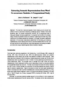
representation scheme is designed for more global navigation. In Section 3. we present a technique for extracting from a simple world scene the textual cues necessary to support this representation scheme. 2. SIGN POST REPRESENTATION The Sign Post Representation (SPR) is a hierarchical representation for capturing the salient points about how an area of space is labeled. SPR represents connectivity but is very sparse; including only the points of interest. The SPR for a street consists of some labeling information, aliases for the name of the street, and information about the known connections with other streets or points of interest. The information about connections can range anywhere from listing every building and intersecting street that exists, to only those that are well known and of major importance. In other words, an SPR does not have to be complete to be useful. The SPR for a building contains a list of floor maps. Each floor map contains a list of hall maps. Each hall map contains the labeling scheme, and connections to the other hall maps and whether those connections occur at the end or between the appropriate labels. Only the important rooms are explicitly represented, with others implicitly represented by the labeling scheme. Each item in an SPR can have a global orientation or a comment on its topology (meandering or circuitous). Orientations may be interspersed with connections and details to express a structure that is changing direction, e.g., a winding road may have different orientations at different points. If, however, there are no details or intersections then only the start and end orientations matter. Figure 1 shows the syntax for SPR. The representation is structured as a set of lists. The first item in the list is an identifier. This can be followed by alternative names for that item, its orientation, topology, and labeling scheme. At the end is a collection of the relationships this item has with other objects in the world. (identifier|sequence [(aliases -alternative ids-)] [(contains -spr-ids-)] [(orientation global-direction)] [(circuit|circuit-left|circuit-right)] [(labels {increasing|decreasing sequential complete|incomplete right-even|right-odd left-even|left-odd (initial initial-value) (final final-value)})] -relationships-) Figure 1: The Syntax of SPR. The relationships relate other objects in the world to the one at the head of the particular SPR. Figure 2 presents a floor map for a building with some of the room numbers given explicitly. This building has a foyer, and then a main hallway that encircles the entire building. There are twelve rooms numbered 101 through 112. The rooms are numbered sequentially with no pattern of odd or even having a particular side preference. Figure 3 gives the SPR for this floor plan. The SPR in Figure 3 is in three pieces. The first is the SPR for the building itself; in this having only containment information. The SPR's for the two parts of the building then follow. There is little of interest in the foyer except how it connects to the main hallway. The SPR for the main hallway contains more information: it is a complete circuit making lefthand turns, at the start you are facing North, the room labels increase as you go, there are no holes in the numbering, and they start at 101 and go through 112. The placement of those rooms numbered explicitly is given in relation to the bends in the hallway. A more complete description of the SPR representation can be found in Reference 14. 3. EXTRACTING TEXT Optical character recognition techniques have now progressed to the point where documents that contain both text and graphics can be processed by nearly automatic means. It is reasonable to ask whether the segmentation techniques used to process such mixed-mode documents could also be applied to a world scene in order to extract sign-post information. We look here to techniques recently described in the literature,15-18 and settle on the basic approach of thresholding the image, filtering connected components based on character-like attributes, and then tracking the centers of individual characters to form
longer strings. This tracking approach is inspired by the tracking algorithms frequently found in raster to vector conversion and/or polygonal approximation systems. 19-24
105
(Post-office
106
101
112
(aliases Figure-3) (containsfoyer hallway-1) (start foyer) (foyer (tee (left (end hallway-1)) (right (start hallway-1)))) (hallway-1 (circuit-left ) (orientationnorth) (labels increasing sequential complete (initial101) (final 112) ) (left 101) (left-bend ) (right 105) (left-bend ) (left 106) (right 110) (left-bend ) (left 112) )
110
Figure 2. Floor map of Post Office
Figure 3. The SPR for the Post Office
The following is a brief overview of the algorithm as it is currently implemented. The process begins with a high resolution gray scale image which is thresholded to form a binary image. Connected components within this binary image are found and some simple attributes such as height, width, density, etc., of each component are computed. Then, depending on the expected size of the text to be detected, components are segmented into those that are likely to be text and those that are not. The non-text components are deleted and the remaining image is then sampled with the center of each text component being mapped to the nearest sampled point. Once this reduced resolution image is formed, adjacent pixels are tracked to form the longest straight line possible. In the ideal situation, the centers of text components that were adjacent characters of a word in the original image would be mapped to adjacent pixels in the sampled image. Of course, the ideal is rarely the case and so the algorithm must also be able to track nearly adjacent pixels as well. Once a text string has been tracked the orientation of the line joining the first and last character is noted and the entire string is rotated to horizontal in order to facilitate automatic character recognition. 3.1. Finding character components Any good connected component finding algorithm could be used in this context. We have chosen to implement a variation of the stack based, scan line algorithm as presented in Reference 25. The assumption is that the entire image is in memory and so the cost of accessing any given pixel is constant, that is, the image does not have to be completely processed in scan line order. Ultimately the finding of connected components could be done in hardware and so the efficiency of this part of the algorithm is not a major concern. We have also chosen to find 4-connected components rather than 8-connected components thereby increasing the number of components eventually found. The trade-off here is in risking that a single character might be broken into two pieces in return for improving the chances that characters will be cleanly segmented from each other and from the surrounding components. Once the connected components have been found, the pixel height, width, area, and aspect ratio of each circumscribing rectangle, as well as the density of the image within each rectangle, are recorded. We have found that area, aspect ratio, and
image density can be misleading so as to cause both types of errors, that is, mislabeling text components as non-text and vice-versa. An upper-case I illustrates the problem. If the string containing this character is oriented horizontally or vertically, then the density of the character is 1.0, the maximum it can be. Also, if the resolution is such that the character is exactly one pixel wide or one pixel high, then the area and the aspect ratio are simply equal to the height or width of the character. If, in addition, the character is oriented at 45 degrees, then the density is the minimum possible value for any connected component, namely, 1/ area . Thus, for legitimate text components, density can take on any possible value, and therefore has no discriminating power, and in some cases area and aspect ratio become simply height or width. The point is that one gains no additional useful information about a component by looking at density, aspect ratio, and area as opposed to looking only at height and width. Let res represent the resolution (in pixels per inch) at which the original document was scanned, let tsize be the size (in inches) of the text to be detected, and let hcurr and w curr be the height and width (in pixels) of the given component. One obvious approach to detecting text is to mark a component as text if both the height and width are below the appropriate pixel threshold, that is if hcurr ≤ 1.4⋅tsize⋅res, and w curr ≤ 1.4⋅tsize⋅res. The factor of 1.4 on the right hand side of the inequalities is to account for characters that are oriented at an angle. The problem of the upper-case I again points out that imposing a lower bound on the height and/or width is inappropriate. The potential difficulty with having no lower bound is that it mismarks extremely small components as text, a problem which could be significant in a noisy image. Noting that every character has at least one dimension that is within about one half of its respective point size, we opt for marking a component as text if either of the following conditions hold: 0.5⋅tsize⋅res ≤ hcurr ≤ 1.4⋅tsize⋅res AND w curr ≤ 1.4⋅tsize⋅res or, 0.5⋅tsize⋅res ≤ w curr ≤ 1.4⋅ptsize⋅res AND hcurr ≤ 1.4⋅tsize⋅res To allow for the simultaneous detection of a range of font sizes within the same document we can modify the above inequalities by replacing tsize with mintsize on the left sides and with maxtsize on the right, where mintsize and maxtsize have the obvious meanings. Note, however, that the larger this range is the less discriminating the test becomes. Finally, we notice that this test will most likely exclude subscripts, superscripts and small punctuation, a problem which might be solved after a string has been tracked by looking for small nearby components. 3.2 Resolution Reduction Once the components have been segmented, those identified as graphics can be subtracted from the image leaving only the text. Following a technique presented in Reference 17, the resolution of this remaining image is then reduced by essentially sampling the image based on the size of the character components. Each text component is mapped to the sample point nearest to the center of that component, see Figure 4. The ideal sampling rate would be such that adjacent characters in the original image get mapped to adjacent pixels in the reduced image. It is, of course, possible to achieve such a mapping only in the case of a image that contains only uniformly spaced text of a single size. In most images there will necessarily be gaps and overlaps in the reduced image.
(a)
(b)
Figure 4. Effects of sampling rate on large and small components.
Referring to Figure 4, let the sampling rate be equal to 0.5⋅mintsize⋅res. With this sampling rate, adjacent characters whose dimensions are approximately mintsize will be mapped to pixels that are one apart from each other rather than adjacent. If the gap between the adjacent characters in the original image is greater than 0.5⋅mintsize, then they will be mapped to pixels that are two apart, and so on. With most text fonts, however, the width of a character is usually closer to one half the corresponding point size and so adjacent characters (that are separated by less than 0.5⋅mintsize) will be mapped to adjacent pixels. It is this fact that motivates the 0.5 in the formula for the sampling rate. Of course, if adjacent characters are less than 0.25⋅mintsize wide and are close enough, then they may be mapped to the same pixel in the reduced image. In this case, the components are linked together and a pointer to the list is stored at the appropriate pixel. When maxtsize is different from mintsize the potential exists for adjacent characters to be mapped to pixels that are at significant distances in the reduced image. If characters from the text font of size maxtsize are adjacent, assuming again that they are approximately 0.5⋅maxtsize wide and are no further than 0.5⋅maxtsize apart, then they will be mapped to pixels that are at a distance of maxtsize/(0.5⋅mintsize) from each other. Keeping maxtsize ≤ 2⋅mintsize will insure that such characters are no more than four pixels apart. Clearly, then, the range of fonts to be detected determines how far apart adjacent characters can be in the reduced image and, in turn, influences the complexity of the tracking algorithm. 3.3 Tracking algorithm The next step in the process is to track the adjacent characters as represented by the reduced image. We look here to a number of algorithms that have been used to produce polygonal approximations to curves in binary images. In particular we note the algorithms of References 21 and 24 as being appropriate starting points for our application. There are, however, two important differences between our application and those for which the existing algorithms were developed. First, since we are attempting to track text strings, we are looking at data that should be straight rather than attempting to use straight segments to approximate data that might really be curved. This allows us to impose slightly more stringent restrictions on the data as it is being tracked. And secondly, because of the effect of the resolution reduction discussed in the previous section, we are faced with tracking data points that are not adjacent. These two facts lead to the following tracking algorithm. The algorithm begins by scanning the entire (reduced) image from left to right and top to bottom searching for a starting point for the first string. Any pixel that is non-zero (ie. corresponds to the center of a text component) can be a starting point. After a starting point is found the reduced image is searched in a neighborhood of that point to find the nearest text component. The size of the neighborhood to be searched is given by (2⋅max(hcurr,w curr))/(0.5⋅mintsize⋅res). This ensures that the next component really is adjacent to the starting point and not a character from a different nearby string. Once the second point is found, the horizontal and vertical offsets from the first point are recorded, and the algorithm then searches in the appropriately sized neighboorhood offset by those same amounts from the second point, and so on. When checking for the nearest component, note that distances are measured in the original image rather than in the reduced image. As soon as two points have been tracked, the angle that the line joining the centers of the two corresponding components forms with the horizontal is computed. Tracking then continues by searching in the appropriately offset neighborhood subject to two additional constraints which insure that the components lie on a straight line. The first is a global angle constraint which requires that the angle between the line joining the starting component to the most previously tracked component and the line joining the starting component to the component being considered is below some threshold. The second is a local angle constraint which requires that the angle between the line joining the starting component to the most previously tracked component and the line joining the previously tracked component to the component being considered is below another threshold. The component under consideration must also be about the same size as the most previously tracked component. If all of these constraints are met, the component is added to the string and tracking continues. Finally, when tracking halts for any reason, the algorithm reverses direction and attempts to extend the string by tracking in the opposite direction. This is necessary because we cannot guarantee that tracking was started at one of the end components of the string. We define a number of identifiers before summarizing the individual steps of the algorithm. Let first, current, and next be the initial component in the string, the currently tracked component, and the next component under consideration by the tracker, respectively. Let rowoff and coloff be the average row and column offsets between successive components for the entire string. Let hcurr,w curr, hnext , and w next be the height and width of the current and next components, respectively, and let aglobal and alocal be the global and local angle thresholds. The steps of the algorithm are as follows: STEP 1) Scan the reduced image left to right and top to bottom until a text component is found. Set first and current to this component, set rowoff and coloff to 0.
STEP 2) Using NC, the nearest component rule, find the nearest component to current in a neighborhood offset from current by (rowoff, coloff). If a component is found, set next equal to the component found, or to 0 if no component is found. STEP 3) If next is not 0, apply A, the angle rule. If A holds, add next to the string, update current, rowoff, and coloff and go to STEP 2. If next is 0 or if A fails, continue to STEP 4. STEP 4) Swap first and current, negate rowoff and coloff and continue tracking in the reverse direction. STEP 5) (Same as STEP 2) STEP 6) (Same as STEP 3, except go to STEP 5 or EXIT) NC (nearest component rule): Set next equal to the nearest component to current within the given neighborhood, where distances are measured in the original image. If no components can be found in this neighborhood, or if either hcurr and hnext or w curr and w next differ by more than a factor of 2, then set next to 0. A (angle rule): The angle between the line joining first to current and the line joining first to next must be less than or equal to α global , and the angle between the line joining first to current and the line joining current to next must be less than or equal to α local
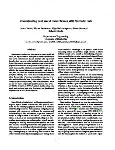
Figure 5. David Miller's door.
Figure 6. Cal Ribbens' door.
4. EXPERIMENTAL RESULTS Figures 5 and 6 show two test images of a typical office doorway. The images were thresholded at decreasing levels of brightness and processed at each level. Figures 7 and 8 show the text extracted from Figures 5 and 6 with only white text against a black background presented here. These results are then to be fed into an automatic character recognition module. Because the characters in Figure 5 are so thin, they are not detected until the last two threshold levels with the first three iterations producing only noise. This noise will be rejected at the character recognition phase. Note that the "E" has been missed because it is far enough away from the "133" to be considered as a separate string and strings consisting of a single character cannot be oriented properly by themselves. Similar results were obtained for the image of Figure 6. Note here that the name plate on room 545 is detected at the third threshold level, but disappears at successive levels. The final iteration produces both of the room numbers and the name plate on room 547.
(a)
(b)
(c)
(d)
(e)
Figure 7. Text extracted from image of Figure 5 at various threshold levels.
(a)
(b)
(c)
(d)
(e)
(f)
Figure 8. Text extracted from image of Figure 6. 5. CONCLUSIONS SPR is a simple, space efficient, easy to use representation scheme for use in maneuvering mobile robots through urban or office domains. The representation can handle incomplete information, does a minimal propagation of erroneous information, and is very robust. Most importantly, SPR provides the navigational cues to maneuver a robot through a complex environment without relying on extraordinary mechanical or sensor accuracy. The cues it provides allow the robot to perceive if it has passed its destination, whether the world has changed, or if it is getting very close. The representation exploits the signs and cues that humans use to navigate about streets and buildings, and therefore it does not require that the
environment be modified in any way to make use of this system. In support of SPR, we have also outlined a possible technique for extracting text from an arbitrary scene. This technique is based on first thresholding the image and then determining connected components. These components are then segmented into text and graphics based on the height and width of their surrounding rectangles, and the algorithm then uses a fast tracking technique to link the characters together into longer text strings. Once the characters have been tracked they are rotated to horizontal for processing by automated character recognition. By using this tracking approach the computational complexity of other techniques, such as the Hough transform, is avoided. The only parameters to the algorithm are the resolution of the input image and the range of text sizes to be detected. 6. REFERENCES 1. 2. 3. 4. 5. 6. 7. 8. 9. 10. 11. 12. 13. 14. 15. 16. 17. 18. 19. 20. 21. 22. 23. 24. 25.
M. Shamos and D. Hoey, "Closest point problems," in Proceedings of the 16th Annual Symp. on Foundations of C.S., ACM, IEEE, pp151-162, (October, 1975). H. P. Moravec, "Certainty Grids for Mobile Robots", in Proceedings of the Workshop on Space Tele-Robotics, JPL Pasadena California (1987). A. Elfes, "Sonar based real world mapping and navigation", IEEE Journal of Robotics & Automation, pp249-265, RA3, #3, (1987). M. G. Slack and D. P. Miller, "Path Planning Through Time and Space in Dynamic Domains", in Proceeding of the 10th IJCAI, AAAI, IJCAI, Milano, Italy, pp 1067-1070, (1987). D. P. Miller and M. G. Slack, "Efficient Navigation Through Dynamic Domains", in the Proceedings of Workshop on Spatial Representation and Multi-Sensor Fusion, St. Charles Illinois, (October 1987). D. V. McDermott and E. Davis, "Planning routes through uncertain territory", Artificial intelligence, v22, pp. 107156, (1984). J. P. Laumond, "Model structuring and concept recognition: Two aspects of learning for a mobile robot", in Proceedings of the 8th IJCAI, IJCAI, pp. 839-841, (1983). E. Davis, Representing and acquiring geographic knowledge, Morgan Kaufman, (1986). R. A. Brooks, Intelligence Without Representation , MIT AI Lab (1987). L. Kaelbling, "An architecture for intelligent reactive systems," in Proceedings of the Workshop on Planning & Reasoning about Action, AAAI, (1986). M. J. Schoppers, "Universal Plans for Reactive Robots in Unpredictable Environments," in Proceeding of the 10th IJCAI, AAAI, IJCAI, Milano, Italy, pp 1039-1046, (1987). M. Georgeff, A. Lansky, and M. Schoppers, "Reasoning and planning in dynamic domains: an experiment with a mobile robot", SRI Tech Note 380, (1986). A. Flynn and R. A. Brooks, MIT Mobile Robots: What's Next, MIT AI Lab Working Paper #302, Nov 1987. D. P. Miller, "A Sparse Spatial Representation for Environments With Textual Cues", working paper, to be submitted to the Eleventh International Joint Conference on Artificial Intelligence, Detroit Michigan, (1989). H. Bunke, "Automatic interpretation of lines and text in circuit diagrams", in Pattern Recognition Theory and Applications, J. Kittler, K. S. Fu, and L. F. Pau, Editors, D. Reidel Boston, pp 297-310, (1982). M. Ejiri, S. Kakumoto, T. Miyatake, S. Shimada, and H. Matsushima, "Automatic recognition of design drawings and maps". Proc. 7th Intl. Conf.on Pattern Recognition pp 1296--1305, (1984). L. A. Fletcher and R. Kasturi, "Segmentation of binary images into text strings and graphics", Proc. SPIE Conf. Applications of Artificial Intelligence 786 , pp 533-540, (1987). J. P. Bixler, "Tracking text in mixed-mode documents", Proceedings of the ACM Conference on Document Processing Systems, Santa Fe NM, (December, 1988). K. Ramachandran, "A coding method for vector representation of engineering drawings". Proc. IEEE 68 pp 813-817 (1980). U. E. Ramer, "An iterative procedure for the polygonal approximation of plane curves", Comput. Graphics Image Process. 1 pp 244-256 (1972). J. Sklansky, and V. M. Gonzalez, "Fast polygonal approximation of digitized curves", Pattern Recognition 12 pp 327331 (1980). I. Tomek, "Piecewise linear approximations", IEEE Trans. Computers C-23 pp 445-448 (1974). K. Wall, and P. Danielsson, "A fast sequential method for polygonal approximation of digitized curves", Comput. Vision Gr.Image Process. 28 pp 220-227 (1984). L. T. Watson, and K. Arvind, R. W. Ehrich, and R. M. Haralick, "Extraction of lines and regions from grey tone line drawing images", Pattern Recognition 17 pp 493-507 (1984). T. Pavlidis, Algorithms for Graphics and Image Processing, Computer Science Press, Rockville, MD. (1982).