example, view morphing[3] method generates a new image easily, though this ..... gle example image,â A.I.Memo No.1531, Artificial Intelligence Laboratory, Mas-.
Face Synthesis with Arbitrary Pose and Expression from Several Images – An Integration of Image-based and Model-based Approaches – Yasuhiro MUKAIGAWA1 , Yuichi NAKAMURA2 and Yuichi OHTA2 1
Department of Information Technology, Faculty of Engineering, Okayama University, Tsushima-naka 3-1-1, Okayama 700, JAPAN 2 Institute of Information Sciences and Electronics, University of Tsukuba, Tennodai 1-1-1, Tsukuba, 305 JAPAN Abstract. We propose a method for synthesizing face views with arbitrary poses and expressions combining multiple face images. In this method, arbitrary views of a 3-D face can be generated without explicit reconstruction of its 3-D shape. The 2-D coordinate values of a set of feature points in an arbitrary facial pose and expression can be represented as a linear combination of those in the input images. Face images are synthesized by mapping the blended texture from multiple input images. By using the input images which have the actual facial expressions, realistic face views can be synthesized.
1
Introduction
A human face includes various information such as individuality and emotion. Techniques for generating a facial image has been studied for many applications. However, a face is the most difficult objects for image synthesis, because we are extremely sensitive to differences between real face images and synthesized face images. We deal with both pose and expression, and aim to synthesize realistic facial images which is almost indistinguishable from real images. In order to synthesize a facial image with arbitrary poses and expressions, some CG (Computer Graphics) techniques are used. A 3-D shape model of a human head is often used and the model is deformed according to the expressions. CV (Computer Vision) is often considered as a useful model acquisition method for CG. The rendering techniques, however, require accurate models which we cannot expect without special devices such as a high precision range finder[1]. It is still intractable with ordinary efforts to measure a precise 3-D face structure with various expressions. As for modeling, FACS (Facial Action Coding System)[2] is often used. A facial expression is described as a combination of the AU (Action Unit). A facial image with an expression is synthesized by deformation defined for each AU, but it is difficult to reproduce the slight changes such as a wrinkle. Thus, synthesized images are still far from a real face appearance as you may see in many applications. Even small modeling errors cause undesirable effect to the synthesized images. On the other hand, there is another paradigm called image-based rendering. It aims to synthesize realistic images by using the textures from real images. For
..
..
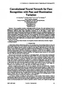
Texture mapping
Calculated coordinates
Triangular patches
Synthesized Image
Input Images Detected points
Fig. 1. Flow of the process
example, view morphing[3] method generates a new image easily, though this method generates only intermediate poses between two views. In order to change the facial poses and expressions of an input image, Poggio, et al. proposed some methods. The linear classes method[4] assumes that one facial image can be represented as a linear combination of multiple facial images of other persons, and synthesizes a new image which has another pose and expression of the target person. However, this method requires a large number of images of other persons for reproducing the individuality. Also, the peculiarities of textures such as moles or birth-marks are not preserved. The parallel deformation method[5] synthesizes intermediate views of two expression images with two poses, but synthesized images are limited to intermediate views between the two views. Therefore, to reproduce a true 3-D rotation with human individuality using image-based rendering is still an open problem. For this purpose, we propose a new method to deal with both rotation and expression in a same framework. We use linear combination to deal with 3-D appearance changes, and texture blending to deal with texture changes. These successfully avoid the difficult problems in 3-D reconstruction and image synthesis. In other words, our method realizes stable image-to-image conversion, that is from the input images to the output synthesized image, by combining image-based and model-based approach. The principle of our framework is based on the structure-from-motion theory. Ullman, et al.[6] proved that an arbitrarily oriented object can be recognized by a linear combination of the 2-D coordinate values of feature points. We have applied this principle to image synthesis and showed that a facial image with arbitrary pose can be synthesized from only two images without explicit 3-D reconstruction[7]. This method can be applied to facial expression synthesis.
2
Basic scheme
Fig.1 shows the flow of the process. A set of images with different facial poses and expressions is used as input. First, 2-D coordinate values of the feature points in the synthesized image are calculated by a linear combination of the feature points detected from the input images. Then, the blended texture which is taken
from the input images is mapped on to the triangular patches whose vertices are the feature points. In the following section, we will explain the method for calculating the coordinate values and the texture mapping.
3
Calculation of 2-D coordinate values
3.1 Facial poses Let B1 and B2 be two input images with different poses. We assume that the feature points are located on the face, and that the correspondences of all feature points between two input images are known. Let (x1k , yk1 ) and (x2k , yk2 ) be 2-D coordinate values of the k-th feature point on images B1 and B2 , respectively. These 2-D coordinate values are the result of rotating and projecting the points (Xk , Yk , Zk ) of the 3-D space. The vectors and matrices which indicate these coordinate values are defined in the followings: x1 = [x11 , x12 , · · · , x1n ] y 1 = [y11 , y21 , · · · , yn1 ] x2 = [x21 , x22 , · · · , x2n ] y 2 = [y12 , y22 , · · · , yn2 ] X1 X2 · · · Xn P = Y1 Y2 · · · Yn Z1 Z2 · · · Zn
(1) (2) (3) (4) (5)
For simplification, we assume rigidity, orthographic projection, and no translation. As shown in equations (6) and (7), the vectors which indicate the coordinate values of the feature points of each input image are represented as a multiplication of the 2 × 3 transformation matrix and the 3-D coordinate values · 1 ¸ · 1 ¸ of the feature points. rx x = P (6) r 1y y1 · 2 ¸ · 2 ¸ rx x = P (7) r 2y y2 ˆ and y ˆ be sets of 2-D coordinate values of the feature points in another Let x ˆ Let rˆ x and rˆ y be the first row vector and the second row vector of the view B. ˆ If r 1x , r 2x , r 1y are linearly independent, transformation matrix corresponding to B. a set of coefficients ax1 , ax2 , ax3 which satisfy equation(8) should exists, because the rank of rˆ x is 3. This means that the X-coordinate values of the all feature ˆ can be represented as a linear combination of 2-D coordinate values points on B on B1 and B2 , as shown in equation(9). rˆ x = ax1 r 1x + ax2 r 2x + ax3 r 1y 1
2
ˆ = ax1 x + ax2 x + ax3 y x
1
(8) (9)
The base vectors of the linear combination are not always linearly independent. In order to get sufficient base vectors stably, we apply the principal
component analysis of the four base vectors (x1 , y 1 , x2 , y 2 ), and we use the first three eigen vectors (p1 , p2 , p3 ) as the base vectors. As shown in equations (10) and (11), X- and Y-coordinate values can be stably represented as linear combinations of the linearly independent vectors. ˆ = ax1 p1 + ax2 p2 + ax3 p3 x ˆ = ay1 p1 + ay2 p2 + ay3 p3 y
(10) (11)
As shown above, the 2-D coordinate values of the feature points can be easily calculated once the coefficients of the linear combination are obtained. In order to determine the coefficients corresponding to the synthesized image, we have two ways; specifying by a sample image and directly specifying the orientation. Specifying by a sample image : A sample image is used for specifying the pose. We synthesize a new image whose pose is the same as this sample image. On the sample images, at least four representative points need to be detected. The coefficients are calculated so that these points of the sample image coincide with the corresponding points of the input images by using a least square method. Directly specifying the orientation : For specifying the pose with an angle, we use representative points whose 3-D coordinates are known. We call these points control points. The control points are rotated to the requested pose, and projected on to the 2-D coordinates. By using these 2-D coordinate values, the coefficients are determined in the same way using sample images. The coefficients of the linear combination are determined from representative points, and the 2-D coordinate values of all feature points on the facial image with arbitrary poses can be calculated. 3.2 Facial expressions We try to synthesize a new image with arbitrary expression. Let Bj (1 ≤ j ≤ m) be input images which have the same pose but different facial expressions. If these input images include a sufficient variety of facial expressions, the coordinate values of the feature points with any expressions can be approximated by the linear combination of those in the input images. Let xj and y j be sets of coordinate values of the feature points on the input ˆ and y ˆ , which indicate sets image Bj . As shown in equation (12), the vectors x ˆ are represented as a linear of coordinate values on a new facial expression B, combination. The 2-D coordinate values of the feature points are calculated with the appropriate coefficients b1 , · · · , bm . ˆ= x
m X j=1
bj xj ,
ˆ= y
m X
bj y j
(12)
j=1
It is convenient to specify the facial expression of the synthesized image by the interpolation of the input images, because no heuristic knowledge is necessary. In this method, a variety of synthesized facial expression depends on the kind of the input images. In other words, if we can prepare a sufficient variety of facial expressions as input images, we can obtain more realistic images.
New pose of ‘neutral’
New pose of ‘smiling’
Two poses of ‘neutral’
Two poses of ‘smiling’ ‘neutral’+‘smiling’
Fig. 2. Integration of pose and expression generation
3.3 Integration of the poses and expressions Since both pose and expression are represented as a linear combination of the coordinate values of the feature points, these can be easily integrated. We assume that a set of input images includes some facial expressions and has at least two different poses for each expression. As shown in Fig.2, we try to synthesize a new image with arbitrary pose and expression from the input images. First, the facial pose in the input images is adjusted to a specified pose for each expression by the method explained in section 3.1. Then, the facial expression is adjusted to a specified expression by the method explained in the section 3.2. The 2-D coordinate values corresponding to a facial pose with an expression can be represented as the linear combination of base vectors shown in equations (13) and (14). Note that ajxi , ajyi , and pji (i = 1, 2, 3) are the coefficients and the base vectors of the j-th expression in the equations (10) and (11), respectively. m 3 m X 3 X X X ˆ= x bj ( ajxi pji ) = bj ajxi pji (13) ˆ= y
j=1
i=1
m X
3 X
j=1
4
bj (
i=1
j=1 i=1
ajyi pji ) =
m X 3 X
bj ajyi pji
(14)
j=1 i=1
Texture mapping
4.1 Texture blending Basically, the textures taken from input images which have similar poses and expressions are mapped onto the synthesized image. However, if we take all the textures from one image with the closest facial pose, the synthesized image will be warped unnaturally as the facial pose changes. This undesirable warping is caused by a drastic deformation of texture. The same can be said to the facial expression. It is obvious that the natural expression can be synthesized by directly using textures of the similar expression rather than by deforming the textures of different expressions. For example, the wrinkles that appear when smiling cannot be synthesized by warping the texture taken from a neutral expression. We can solve this problem by texture blending. In our method, facial images are synthesized by mapping the blended texture taken from multiple input images. The weight for blending is set larger for the similar pose and expression.
(a) 2-D triangular patches
(b) Two input images
(c) Synthesized images
Fig. 3. Synthesized images of various poses using two input images
Although the facial orientation of the input image is unknown, a rough orientation can be estimated by the factorization method[8]. First, several feature points which do not move by the facial expression changes, such as the top of nose, are selected. Then, the relative facial orientation of the sample image is estimated. Since this value is only used for determining the texture blending weights, small errors are not critical. The weights of the texture blending are determined to be inversely proportional to the square of the angle difference of facial orientations. The weights of the blending for facial expression are determined in proportion to the coefficients bj in the equation (12). 4.2 Two dimensional texture mapping The texture is mapped by using triangular patches whose vertices are the feature points. For each triangular patch, the texture is clipped from multiple input images, and deformed by affine transformation according to the 2-D coordinate values of the feature points. Then, the textures are blended by using the weights and mapped. In this step, it is checked whether each patch is obverse or reverse. The texture is not mapped on to the reverse patch. This simple judgment is enough for facial image synthesis, because complicated occlusion never occurs.
5
Experiments
We chose 86 feature points on a face. The number is relatively small compared to the ordinary facial models used in other applications. These feature points are located not only on the facial components such as eyes and mouth, but also on the movable parts such as cheeks. The 2-D coordinate values of the points are
(a) Sample image (b) Synthesized image Fig. 4. Sample image and synthesized image
given manually by referring to the marks drawn on the face. The 156 triangular patches are created as shown in Fig. 3(a). First, we show the experimental results whose facial poses are specified directly by the control points. Two input images are shown in Fig.3(b). Five points (ends of both eyes, top of nose, and bottoms of both ears) were chosen as the control points with known 3-D coordinates. The synthesized images with various poses are shown in Fig. 3(c). We can see that true 3-D rotations are realized. Next, in order to compare the synthesized image and the real image, we synthesize a new image which has the same pose as the sample image from two input images shown in Fig.3(b). A sample image was prepared as shown in Fig.4(a). On the sample image, five feature points (ends of both eyes, top of nose, and bottoms of both ears) were manually detected. A new facial image was synthesized and overwritten onto the sample image as shown in Fig.4(b). The outer region of the face such as hair, boundary, and background is copied from the sample image and the inner region of the face is overlaid by the synthesized image. As we can see in this example, the synthesized images are often indistinguishable from real images. Last, we show the results of changing facial expressions of a sample image. The input images include two different poses for each three different expressions as shown in Fig.5(a). Fig.5(b) shows two sample images which are the same person as the input images. New images with different expressions were synthesized and overwritten onto each sample image as shown in Fig.5(c).
6
Conclusion
We have proposed a new method for synthesizing facial views with arbitrary poses and expressions without explicitly modeling the 3-D shape and the facial expression. We have shown that both of the poses and the expressions are treated in a unified way. We have implemented this method and demonstrated that the natural facial images can be synthesized. The number of facial expressions that can be synthesized in the current system is limited, because we used only few kinds of facial expressions. In order to
(a) Input images with three expressions
(b) Sample images
(c) Synthesized images with various expressions
Fig. 5. The results of changing facial expressions of sample images
synthesize arbitrary facial expression, we are now working on a new framework which utilizes a set of typical expressions obtained from a sequence of images.
References 1. T.Akimoto and Y.Suenaga, “Automatic Creation of 3D Facial Models”, IEEE Computer Graphics and Applications, September 1993, pp.16–22, 1993. 2. P.Ekman, and W.V.Friesen, “Facial action coding system”, Consulting Psychologists Press, 1977. 3. S.M.Seitz, and C.R.Dyer, “View Morphing”, Proc. SIGGRAPH’96, pp.21–30, 1996. 4. T.Vetter and T.Poggio, “Linear object classes and image synthesis from a single example image,” A.I.Memo No.1531, Artificial Intelligence Laboratory, Massachusetts Institute of Technology, 1995. 5. D.Beymer, A.Shashua, and T.Poggio, “Example based image analysis and synthesis,” A.I.Memo No.1431, Artificial Intelligence Laboratory, Massachusetts Institute of Technology, 1993. 6. S.Ullman, and R.Basri, “Recognition by linear combinations of models”, IEEE Trans. PAMI, vol.13, no.10, pp. 992–1006, 1991. 7. Y.Mukaigawa, Y.Nakamura, and Y.Ohta, “Synthesis of Arbitrarily Oriented Face Views from Two Images”, Proc. ACCV’95, Vol.3, pp.718-722, 1995. 8. C.Tomasi, and T.Kanade, “The factorization method for the recovery of shape and motion from image streams”, In Proceedings of Image Understanding Workshop, pp. 459–472, 1992.