Facility layout and location problems arise in a variety of contexts (Francis et al.
1992) ... layout problems consider placement of finite-sized facilities, while facility
...
Facility Placement with Sub-Aisle Design in an Existing Layout Min Zhang1 , Sel¸cuk Savas2 , Rajan Batta
∗3
, and Rakesh Nagi3
1
Avis Budget Group Inc., 6 Sylvan Way, Parsippany, NJ 07054 Department of Industrial Engineering, IS¸IK University, Istanbul, Turkey Department of Industrial and Systems Engineering, 438 Bell Hall, University at Buffalo (SUNY), Buffalo, NY, 14260, USA
2 3
Final revision June 2008
Abstract In this paper we consider the integration of facility placement in an existing layout and the configuration of one or two connecting sub-aisles. This is relevant, for example, when placing a new machine/department on a shop floor with existing machines/departments and an existing aisle structure. Our work is motivated by the work of Savas et al. (2002), that considered the optimal planar placement of a finite-size facility in the presence of existing facilities. Our work differs from theirs in that we consider material handling to be restricted to the aisle structure. We do not allow the newly placed facility to overlap with existing facilities or with the aisle structure. Facilities are rectangular and travel is limited to new or existing aisles. We show that there are a finite number of candidate placements for the new facility. Algorithms are developed to find the optimal placement and the corresponding configurations for the subaisles. Complexity of the solution method is analyzed. Also, a numerical example is provided to explore the impact of the number of sub-aisles added.
Keywords: Facility Design, Facility Placement, Sub-aisle Configuration.
1
Introduction
Facility layout and location problems arise in a variety of contexts (Francis et al. 1992). Facility layout problems consider placement of finite-sized facilities, while facility location problems consider placement of infinitesimal-sized facilities, perhaps in the presence of finite-sized barriers to travel or forbidden regions for locating new facilities. In facility layout and location problems, the material handling between facilities is assumed to take place along a shortest feasible rectilinear/Euclidean path. This assumption often leads to inaccurate distance measurements in a plant layout application, because material handling clearly has to take place through an aisle structure, i.e. travel has to be restricted to a material handling network. In network location problems, travel between facilities is assumed to occur through an underlying network, additionally both the existing facilities on the network and the new facilities to be located are assumed to be of infinitesimal ∗
To whom all correspondence should be addressed. E-mail:
[email protected]
1
size. The latter assumption is also not valid for plant layout problems. Recognizing the relevance of facility size and the existence of aisles for material handling between facilities in a plant, we address the layout addition problem of placing a rectangular new facility in a plane in the presence of other rectangular existing facilities and an aisle structure. We consider the cases of placing the new facility directly onto the existing aisles and adding one or two sub-aisles to connect the new facility to the existing aisles. The rest of the paper is organized as follows. Section 2 provides a literature review. In Section 3, we formally introduce and define the problem. In Section 4, we describe a grid construction procedure. In Section 5, we detail our approach to the problem, considering both the situation of adding a new facility directly onto the existing aisle structure, and the simultaneous consideration of placement of a new facility and configuration of sub-aisles. The complexity of our solution algorithm is analyzed in Section 6. An example is presented in Section 7. Finally, a summary and conclusions of our work are presented in Section 8.
2
Literature Review
Restricted location problems are the closely related research areas to our work where restrictions are imposed on locating new facilities. The restricted area falls into three classes: barriers (which prohibit location and travel), forbidden regions (which prohibit location but permit travel at no extra cost), and generalized congested regions, GCR (which prohibit location but permit travel at a penalty). For restricted location problems, readers are referred to Katz and Cooper (1981), Larson and Sadiq (1983), Batta et al. (1989), Aneja and Parlar (1994), Butt and Cavalier (1996), Klamroth (2000), Dearing et al. (2002) and Nandikonda et al. (2003), among others. In all the studies referenced above, the authors assumed that the new facilities to be located were infinitesimal. Recognizing the practical relevance of facility size consideration, Savas et al. (2002) first considered the optimal placement of a finite-size new facility in the presence of arbitrarilyshaped barriers with the median objective and rectilinear distance metric. Variant works of Savas et al. (2002) have been studied by Sarkar et al. (2005), Kelachankuttu et al. (2007) and Sarkar et al. (2007). Sarkar et al. (2005) considered the placement of a finite-size new facility in the presence of existing facilities with a median objective, rectilinear distance metric, and rectangular shaped facilities. The restricted area is in the form of generalized congested regions as compared to barriers in Savas et al. (2002), additionally the area of the new facility to be located is known but its exact dimensions are to be determined, whereas the shape of the new facility is known a priori in Savas et al. (2002). Kelachankuttu et al. (2007) developed contour lines with respect to placing a new rectangular facility in the presence of rectangular existing facilities. Their study is important when the optimal site is not suitable for facility placement with practical constraints. Sarkar et al. (2007) revisited the study of Savas et al. with a center objective. 2
The above studies assumed that the material handling between facilities took place along a shortest feasible rectilinear path between the facility servers (I/O points). As claimed in the introduction, interaction between facilities is normally restricted to a material handling network in a plant layout application. A wide variety of network location problems have been studied, for example, p-median problem (Hakimi 1964), fixed charge location problem (Kuehn and Hamburger 1963), set covering location problem (Toregas et al. 1971), maximal covering location problem (Church and ReVelle 1979), etc. An excellent review of discrete network location problems can be found in Drezner and Hamacher (2004). In an attempt to relax the assumption that the underlying network is given, facility location-network design models were proposed, for example, Melkote (1996) proposed models to simultaneously optimize facility location and the underlying network design. Generally, facility location-network design models and network design models do not take into account the issue of the facility’s size, which is of obvious importance in plant layout. This motivates the work presented in this paper. Our work, in a way, may be also viewed as an extension of the work by Savas et al. (2002). We consider placing a new facility while using an existing aisle structure. As travel is restricted to the aisles, it may be necessary and/or advantageous to construct new sub-aisles which connect the new facility to the existing aisle structure. Motivated by these considerations we analyze the problem of placement of a finite-size new facility as well as connection of the new facility to the existing aisle structure with restricting travel on aisles.
3
Problem Description
3.1
Problem Statement
The problem that we address is that of placing a new facility (NF) in a manufacturing plant. This NF must be placed so that it does not overlap either the existing facilities (EFs) or the existing aisle structure. For the sake of analytical tractability we make several key simplifying assumptions: • The plant is rectangular. • The EFs are rectangular, with the sides of each EF parallel to the sides of the plant. • There is an existing aisle structure through which all material handling takes place. The segments of this aisle structure are parallel to the sides of the plant. • Each EF has a single I/O point which is located on the aisle structure. • The NF is rectangular and placement must be done so that the sides of the NF are parallel to the sides of the plant. • The NF has a single I/O point. 3
The first version of the problem we consider is when no new aisles can be constructed. Thus the NF has to be placed so that its I/O point coincides with the existing aisle structure. In this case we focus on the objective of minimizing the material handling cost between the EFs and the NF. The second version of the problem is when sub-aisle construction is permitted to connect the NF to the existing aisle structure. Both the cases of one new sub-aisle and two new sub-aisles are examined. Each newly constructed sub-aisle must be parallel to the sides of the plant, and it cannot overlap with the existing aisles except for exactly one connection point where the new subaisle intersects the existing aisle structure. The introduction of one or two sub-aisles can decrease the shortest distance between two EFs. Thus the objective in this case is minimization of the total material handling cost (i.e. between the EFs, and between the NF and EFs) plus the cost of constructing sub-aisles.
3.2
Definitions and Notation
We assume that each facility, including the new one, is a rectangular region of finite area in < 2 . Let Bj denote the set of points (x, y) ∈ f1 (X, ¯ z) + f3 (X, ¯ z). f1 (X, ¯ z 0 ) > f3 (X, ¯ z). It is obvious that f3 (X, ¯ z 0 ) ≥ f1 (X, ¯ z), using similar arguments to those in Hakimi The following proof shows f1 (X, ¯ more efficiently through node u and N2 as (1964). N1 is defined as the set of nodes that reaches X ¯ more efficiently through v, with ties broken arbitrarily. N1 and N2 are the set of nodes reaching X ¯ z) thus mutually exclusive sets whose union is equal to D. If the sub-aisle aisle changes from ( X, ¯ z 0 ), nodes in N1 require a longer distance to reach X ¯ through u. For those nodes in N2 , the to (X, ¯ through v remains unchanged. The result follows. 2 distance to X ¯ X
PSfrag replacements u
z
z’
v
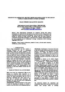
Figure 7: Sub-aisle connection to an existing edge. Lemma 1 implies that the best configuration of a single sub-aisle uses the shortest feasible rectilinear path between the location of the NF and an edge that need to be connected. Note that there possibly exist multiple shortest feasible rectilinear paths from a location to an edge, in other words, multiple optimal configurations of a single sub-aisle may exist. In this case, one of the shortest feasible rectilinear paths can be determined using an algorithm similar to the one in Larson and Li (1981). In the following sections of the paper, the best configuration of a single sub-aisle is defined as the shortest feasible rectilinear path determined by using such an algorithm. According to Lemma 1, Algorithm 1 in the following chooses the best solution from all the combinations of a NF’s location and an edge. Algorithm 1 (Single New Facility, One Sub-aisle Case) 1. FOR each cell C ⊂ F 2. 3. 4.
IF FC 6= φ THEN For each R(FC ) ⊂ FC FOR each edge (u, v) ∈ A 11
5.
¯ ∈ R(FC ) FOR each candidate location X
6.
¯ to (u, v) Determine the shortest feasible rectilinear path from X
7.
Evaluate the objective function and record the best solution
Algorithm 1 will achieve the optimal solution within finite steps only if there are a finite number of candidate locations to be considered in each R(FC ) ⊂ FC . Lemma 2 below shows that at most two candidate placements in each R(FC ) ⊂ FC with respect to edge (u, v) need to be considered. Lemma 2 Given an edge (u, v) and a cell C, at most two candidate placements with respect to edge (u, v) for the NF in each R(FC ) ⊂ FC need to be considered and the candidate placement is one of the corners of R(FC ). Proof: (1) We first start with the case where edge (u, v) is inside the span of cell C and also visible to C, as Figure 8 illustrates. The NF and R(FC ) are shown in Figure 8. It is obvious that any placement inside R(FC ) is dominated by at least one placement on segment [E1 (R(FC )), E2 (R(FC ))], which is the closest side to (u, v). According to the main nodal optimality result in Hakimi (1964), it ¯ z) + f3 (X, ¯ z) is concave over segment is not difficult to show that the objective function f1 (X, [E1 (R(FC )), E2 (R(FC ))]. Thus the candidate placements should be E1 (R(FC )) and E2 (R(FC )). In general, the two corners on the side of R(FC ), which is parallel and closer to (u, v), are the candidate placements. This establishes the result for this specific situation. (2) Many other cases are possible as illustrated in Figure 6. In these cases, we first prove the ¯ ∈ R(FC ) following statements: (a) a shortest feasible rectilinear path from any placement at X to edge (u, v) will intersect edge (u, v) either at u or v, i.e. one of the end nodes of (u, v); (b) a shortest feasible rectilinear path which passes through Ck and Ek (R(FC )), k ∈ {1, 2, 3, 4}, exists ¯ ∈ R(FC ) to u (v). We then demonstrate that Lemma 2 holds according to statements (a) from X and (b). For the case where edge (u, v) is outside the span of C and visible to C (Figure 6.b), it is ¯ ∈ R(FC ) to (u, v) must intersect (u, v) obvious that the shortest feasible rectilinear path from X at u or v. If edge (u, v) is invisible to C, it could be inside or outside the span of C (see Figures 6.c and 6.d). The same argument is employed to prove these two sub-cases. Suppose that the shortest ¯ ∈ R(FC ) to edge (u, v) intersects (u, v) at z instead of u or v, there feasible rectilinear path from X must exist at least one EF (acting as a barrier) to drive the shortest feasible rectilinear path from ¯ ∈ R(FC ) to (u, v) to arrive at z, as shown in Figure 9. In this case, edge (u, v) would not exist X according to the grid construction procedure in Section 3.1.
12
Therefore statement (a) follows. According to Result 2, a shortest feasible rectilinear path ¯ which passes through cell corner Ck and corner Ek (R(FC )), k ∈ {1, 2, 3, 4} exists from u (v) to X ∈ R(FC ). Statement (b) follows. Statements (a) and (b) together show that any placement inside R(FC ) is dominated by one of ¯ u) ≥ mink∈{1,2,3,4} {r(Ek (R(FC )), u)} the corners Ek (R(FC )), k ∈ {1, 2, 3, 4}. This is because r(X, ¯ v) ≥ mink∈{1,2,3,4} {r(Ek (R(FC )), v)}. Therefore we let Eu denote the set of corners such or r(X, that the corresponding shortest feasible rectilinear paths share node u as a connection point. Similarly, Ev is defined as the set of corners such that these paths share node v as a connection point. Let r(Ek (R(FC )), (u, v)) denote the shortest feasible rectilinear distance from corner Ek (R(FC )), k ∈ {1, 2, 3, 4} to edge (u, v). Let kˆu = argmin{r(Ek (R(FC )), (u, v)), k ∈ Eu } and kˆv = argmin{r(Ek (R(FC )), (u, v)), k ∈ Ev }, then Ekˆu (R(FC )) and Ekˆv (R(FC )) are the candidate PSfrag replacements placements. 2 C
C4
#!$! # $! # $! # $! # $! # $! # $# #!$! # $! # $! # $! # $! # $! # $# #!$! # $! # "! # "! # " $! # $! # $# $! $!
C3 E4 (R(FC ))
¯ H(X)
E3 (R(FC ))
R(FC ) u
z
¯ X C1
u
E1 (R(FC ))
C2 E2 (R(FC )) PSfrag replacements v
v
"!"!" "!"!" "!"!"
¯ X
C
Figure 9: Connection at end nodes of an edge.
Figure 8: Candidate placements with respect to an edge.
Lemma 2 permits us to arrive at the following result. Theorem 2 There are a finite number of candidate placements for the NF and a finite number of candidate configurations of one sub-aisle that need to be considered when seeking an optimal solution for placement of NF and construction of one sub-aisle. Proof: The feasible region for the placement of the NF is divided into a finite number of cells. Also, there are a finite number of edges in the existing aisle structure. Thus the number of combinations of cell/edge is finite. According to Lemma 2 and the fact that at most three sub-rectangles can be formed in each cell, each cell/edge combination considers at most six candidate placements for the NF. Since the best sub-aisle configuration from one location to one edge is defined as the shortest feasible rectilinear path between them determined by an algorithm similar to the one in Larson and Li (1981), the number of candidate sub-aisle configurations is also finite. The result follows. 2 13
5.3
Placement of One New Facility and Configuration of Two Sub-Aisles
We now consider the case of constructing two sub-aisles from the NF to the existing aisle structure. For this case we also need to take into consideration the material handling costs between the EFs, since the addition of two new sub-aisles may create a shorter alternate path for some of the existing flows. The two new sub-aisles intersect the existing aisle structure at two connection points (denoted by z1 and z2 ), f1 (`), f2 (`) and f3 (`) are rewritten as follows: ¯ ¯ ¯ z 1 , z2 ) = P f1 (`) = f1 (X, i∈D wi min{d(i, z1 ) + r(z1 , X), d(i, z2 ) + r(z2 , X)}, P ¯ z 1 , z2 ) = P f2 (`) = f2 (X, i∈D j∈D hij d` (i, j), and ¯ ¯ ¯ f3 (`) = f3 (X, z1 , z2 ) = K[r(z1 , X) + r(z2 , X)]. where the subscript ` signifies that the shortest distance between EF i and EF j may change due to the two newly constructed sub-aisles. ¯ z1 , z2 ) = f1 (X, ¯ z1 , z2 ) + f2 (X, ¯ z1 , z2 ) + f3 (X, ¯ z1 , z2 ). The optimization problem can be Let f (X, restated as follows: ¯ z1 , z2 ) + f2 (X, ¯ z1 , z2 ) + f3 (X, ¯ z1 , z2 )}. min min {f1 (X,
¯ z1 ,z2 ∈G X∈F
Lemma 3 presents a result similar to that in Lemma 1. ¯ the optimal sub-aisles from X ¯ to two given separate edges consist Lemma 3 Given a location X, ¯ to each edge. of two shortest feasible rectilinear paths from X u1 z10
v1
z1
PSfrag replacements C
¯ X
u2
z20
z2
v2
Figure 10: Shortest path connection to sub-aisles. Proof: Consider edges (u1 , v1 ) and (u2 , v2 ) in Figure 10 where both edges are horizontal. Let z1 ¯ to edge (u1 , v1 ) and (u2 , v2 ), respectively, and and z2 denote the shortest connection points from X ¯ > r(z1 , X) ¯ and r(z 0 , X) ¯ > r(z2 , X). ¯ It is let z10 , z20 denote any connection points such that r(z10 , X) 2 ¯ z 0 , z 0 ) > f3 (X, ¯ z1 , z2 ). obvious that f3 (X, 1
2
14
¯ most efficiently Similarly, N1 , N2 , N3 and N4 are defined as the sets of nodes that reach X through u1 , v1 , u2 and v2 , respectively (with ties broken arbitrarily). Following the logic presented ¯ z 0 , z 0 ) ≥ f1 (X, ¯ z1 , z2 ). in the proof of Lemma 1, it is easy to show that f1 (X, 1
2
¯ z 0 , z 0 ) ≥ f2 (X, ¯ z1 , z2 ). Again, applying the same logic, we have f2 (X, 1 2 The above demonstrates the result in the case where both edges are horizontal. Following the same logic, the result can also be established for the case where one edge is horizontal and one edge is vertical. Lemma 3 follows. 2 Lemma 3 implies that an algorithm similar to Algorithm 1 can be developed to evaluate all the combinations of a candidate locations for the NF and two edges. Therefore we first show in Lemma 4 that the candidate locations in R(FC ) with respect to two edges are finite in a special case, then extend this result for a general case in Theorem 3. Finally, Algorithm 2 is presented for determining the optimal solution for the two sub-aisles case. ¯ z1 , z2 )|e ,e where the conditional subscript on e1 Before stating Lemma 4, we introduce f (X, 1 2 and e2 signifies the condition of being given z1 ∈ e1 and z2 ∈ e2 . Lemma 4 Consider two separate edges e1 , e2 and a cell C, with the property that both edges are ¯ z1 , z2 )|e ,e is concave over the set R(FC ). visible to C, as shown in Figure 11. The function f (X, 1 2 u1 (E1 )
v1 (E2 )
( )( )& )( B)( &
1
PSfrag replacements
θ δ
∆
% '% '& '% '% &
B2
u2 (E3 )
v2 (E4 )
Figure 11: Movement of the NF within a cell. Proof: We start with the case where both edges are horizontal. In the case where one edge is horizontal and one edge is vertical, the result can be demonstrated with the same argument. The following proof refers to Figure 11. Let e1 , e2 denote edges (u1 , v1 ) and (u2 , v2 ) respectively. We have ¯ z1 , z2 )|e ,e = f1 (X, ¯ z1 , z2 )|e ,e + f2 (X, ¯ z1 , z2 )|e ,e + f3 (X, ¯ z1 , z2 )|e ,e . f (X, 1 2 1 2 1 2 1 2 ¯ z1 , z2 )|e ,e is concave over R(FC ). (1) We first prove that f1 (X, 1
2
15
Consider a location B1 ∈ R(FC ). Further consider some feasible direction of movement from location B1 , as shown in Figure 11, to a location B2 , where B2 ∈ R(FC ). Also any location ∆ on the line segment joining B1 and B2 has the property ∆ ∈ R(FC ) (If no such point B2 exists, then R(FC ) is a singleton set and the result follows). Let the variable δ parametrize the movement along B1 B2 which is δ Euclidean distance units from B1 . For the sake of notation simplicity, let E1 , E2 , E3 and E4 denote u1 , v1 , u2 and v2 respectively, as shown in Figure 11. We have P f1 (∆, z1 , z2 )|e1 ,e2 = i∈D wi mink {d(i, Ek ) + d(Ek , ∆)}.
For given k, d(i, Ek ) is constant with respect to δ, and it is easy to show that d(Ek , ∆) is linear
in δ :
d(Ek , B1 ) + δ(+ cos θ + sin θ) d(Ek , B1 ) + δ(− cos θ + sin θ) d(Ek , ∆) = d(Ek , B1 ) + δ(+ cos θ − sin θ) d(Ek , B1 ) + δ(− cos θ − sin θ) where θ is as shown in Figure 11.
for for for for
k k k k
= 1, = 2, = 3, = 4,
Therefore d(i, ∆) = mink {d(i, Ek ) + d(Ek , ∆)} is the minimum of four linear functions and is concave. Because f1 (∆, z1 , z2 )|e1 ,e2 is the sum of positively weighted concave functions, it is also concave. (2) We now prove that f2 (∆, z1 , z2 )|e1 ,e2 is also concave over R(FC ). The two new sub-aisles may create a shorter alternate path for some of the existing flows. Therefore f2 (∆, z1 , z2 )|e1 ,e2 = d∆ (i, E2 , E4 , j)},
P
i∈D
P
j∈D
hij min{d(i, j), d∆ (i, E1 , E3 , j), d∆ (i, E1 , E4 , j), d∆ (i, E2 , E3 , j),
where d∆ (i, Ek , El , j) = d(i, Ek ) + d(Ek , ∆) + d(∆, El ) + d(El , j), k, l = 1, 2, 3, 4. d(i, j), d(i, Ek ) and d(El , j) are constants with respect to δ, and it is easy to show that d(Ek , ∆)+ d(∆, El ) is linear in δ. We have
d(Ek , B1 ) + d(B1 , El ) + δ(+2 cos θ) for k = 1, l = 3, d(Ek , B1 ) + d(B1 , El ) for k = 1, l = 4, d(Ek , ∆) + d(∆, El ) = d(E , B ) + d(B , E ) for k = 2, l = 3, 1 1 k l d(Ek , B1 ) + d(B1 , El ) + δ(−2 sin θ) for k = 2, l = 4. Therefore D∆ (i, j)=min {d(i, j), d∆ (i, E1 , E3 , j), d∆ (i, E1 , E4 , j), d∆ (i, E2 , E3 , j), d∆ (i, E2 , E4 , j)}
is the minimum of five linear functions and therefore concave. Because f2 (∆, z1 , z2 )|e1 ,e2 is the sum of positively weighted concave functions, it is also concave. (3) Since f3 (∆, z1 , z2 )|e1 ,e2 = f3 (B1 , z1 , z2 )|e1 ,e2 , f3 (∆, z1 , z2 )|e1 ,e2 is constant with respect to δ and therefore concave. ¯ z1 , z2 )|e ,e is concave over R(FC ). 2 We conclude that f (X, 1 2 It is probable that an edge is invisible to a cell as Figure 12 illustrates. This case complicates the analysis. We now introduce several definitions similar to those defined in Nandikonda et al. 16
¯ ∈ R(FC ) to edge (u, v) passes through either (2003). A shortest feasible rectilinear path from X one of the cell corners if (u, v) is outside or invisible to cell C. We call that the assignment of edge (u, v) to cell corner Ck , if this shortest feasible rectilinear path passes through Ck , k = 1, 2, 3, 4. If ¯ ∈ R(FC ) to edge (u, v) passes through Ck , its distance the shortest feasible rectilinear path from X ¯ (u, v)) = d(X, ¯ Ck ) + r(Ck , (u, v)), where r(Ck , (u, v)) function can be explicitly presented as r(X, is a constant. -+ . -+ . -+ . -+ . -+ . -. u 1 -+ + + + . . . . -+ . v1 -. - .+ - .+ - .+ - ..-+.+ - .+ - .+ - .+ - ..-+.+ C
PSfrag replacements / 0+ / 0+ / 0+ / 0/ 0+ / 0+ / 0+ / 0/ 0/+0+ / 0+ / 0+ / 0/ 0/+0+
* ,+ * ,* ,+ * ,* ,*+,+ * ,* ,*+,+
u2
v2
Figure 12: Edge (u1 , v1 ) invisible to cell C. ¯ in However, the assignment of edges to cell corners can change upon moving the placement X ¯ ∈ R(FC ) is to the left R(FC ), as illustrated by the example in Figure 13. When the placement X ¯ to (u, v) goes side of, but not on line segment C5 C6 , a shortest feasible rectilinear path from X ¯ ∈ R(FC ) is to the right side of, but not on line segment C5 C6 , through cell corner C1 . While if X ¯ ∈ R(FC ) on line segment C5 C6 , both alternatives the path goes through cell corner C2 . For X (going through C1 or C2 ) are equally attractive. For this reason, we call the line segment C5 C6 an Equal Travel Time Line (ETTL). Similar definitions can be found in Nandikonda et al. (2003).
PSfrag replacements
C4
C6
C3 C
R(FC )
1232 1 32 1 32 1 32 1 32 1 32 1 32 1 32 1 32 1 31 C C 1 2 C 1232 1 32 1 32 1 32 1 32 1 32 1 5 32 1 32 1 32 1 31 1232 1 32 1 32 1 32 1 32 1 32 1 32 1 32 1 32 1 31
u
v
Figure 13: Example for varying cell corner assignment to edge. We follow the procedure established in Nandikonda et al. (2003) to construct ETTLs associated 17
with an edge (u, v) and a cell C. Note that the edge is outside the span of the cell or invisible to ¯ ∈ R(FC ) to (u, v) may not pass through it, otherwise the shortest feasible rectilinear path from X the cell corners as shown in Figure 5.a. In fact, an edge will generate at most one ETTL in a cell − see Nandikonda et al. (2003). ¯ (u, v)) The distinctive feature of a sub-cell of R(FC ) is that the form of the distance function r(X, ¯ is within a sub-cell of R(FC ). This is because for any X ¯ within a does not change as long as X sub-cell of R(FC ), a shortest feasible rectilinear path always goes though the same corner of C. Combining this observation and Lemma 4, we arrive at the following result. ¯ z1 , z2 )|e ,e is concave over each sub-cell of R(FC ), where cell C Theorem 3 The function f (X, 1 2 belongs to the finite number of cells in the feasible region as formed in Section 3 and the sub-cells of R(FC ) are formed by the ETTLs associated with e1 and C, and e2 and C. ¯ (u, v)) does not change as long as X ¯ is within Proof: Since the form of the distance function r(X, a sub-cell of R(FC ), a similar argument to that used in the proof of Lemma 4 allows us to conclude ¯ z1 , z2 )|e ,e is concave over each sub-cell of R(FC ). 2 that f (X, 1
2
Algorithm 2 (Single New Facility, Two Sub-aisles Case) 1. FOR each cell C ⊂ F . 2. 3. 4.
IF FC 6= φ THEN FOR each R(FC ) ⊂ FC FOR each edge (ui , vi ) ∈ A
5.
Generate the ETTL associated with (ui , vi ) and C
6.
FOR each edge (uj , vj ) ∈ A (j 6= i)
7.
Generate the ETTL associated with (uj , vj ) and C
8.
Let CORNER denote the set of corners associated with the sub-cells of R(F C )
9.
FOR each corner in CORNER
10.
Find the shortest feasible rectilinear path from the corner to (u i , vi )
11.
Find the shortest feasible rectilinear path from the corner to (u j , vj )
12.
Evaluate the objective function and record the best solution
18
The complexity analysis of Algorithms 1 and 2 is presented in Section 5. We briefly discuss the placement of multiple NFs. In this case, we need to consider the interactions between NFs and EFs as well as between NFs and NFs. A straightforward heuristic is to place one NF at one time sequentially, using Algorithm 1 or Algorithm 2.
6
Solution Complexity
It is clear that our solution method for the no sub-aisle situation has a finite number of steps. For the one sub-aisle case and two sub-aisles case, the number of cells is an important factor governing the solution complexity. Formally, n rectangular EFs generate at most 3n vertical gridlines and 3n horizontal gridlines. Note that one gridline is generated from each EF associated with its single I/O point. Suppose that the original material handling network has av vertical arcs and ah horizontal arcs. We use a to signify the upper bound over av and ah , i.e. a = max{av , ah }. In the worst case a additional vertical gridlines and a additional horizontal gridlines are generated. Now we are ready to analyze the solution complexity. The number of cells generated is at most (3n + a + 1)2 , therefore the number of sub-rectangles of feasible region is at most 3(3n+a+1)2 The number of edges is at most 2a(3n+a). Accordingly, the number of edge pairs is bounded by 2a2 (3n + a)2 . Therefore the solution complexity of Algorithm 1 in the worst case is 12a(3n + a + 1)2 (3n + a). In addition, an edge pair will generate at most two ETTLs within a cell because each edge can generate at most one ETTL associated with this cell. Consequently, at most 9 corners (candidate placements) associated with a sub-rectangle of a cell are under consideration in Step 9 of Algorithm 2. As a result, the solution complexity of Algorithm 2 in the worst case is 54(3n+a+1) 2 a2 (3n+a)2 . Note that the above analysis does not include the complexity of finding feasible regions and the complexity of finding the shortest feasible rectilinear paths.
7
Example
This section illustrates our solution methodology with the aid of an example, depicted in Figure 14. The EFs, I/O locations, hij s and wi s are shown in Figure 14. The bold lines in Figure 14 are the existing aisles. The dimensions of the NF and its I/O location can also be obtained from Figure 14. Following the grid construction procedure, we draw several horizontal and vertical lines (dashed lines in Figure 14). Suppose that the unit construction cost K = 2. First we identify the region for feasible placements, which is illustrated in Figure 15. As we can see, the feasible region is divided into a set of rectangular cells. There are 12 cells (labeled with “A” through “L”) and 18 edges (labeled with “a” through “r”) under consideration. For the case when no sub-aisle is constructed,
19
1
: ;+ : ;+ : ;+ : ;: ;+ : ;+ : ;+ : ;: ;:+;+ : EF1 : ;+ : ;: ;:+;+ ;+ : ;+ : ;+ : ;: ;:+;+ : ;+ : ;+ : ;: ;:+;+ : ;+ : ;+ : ;: ;:+;+
17 16 15 14 13 12 11 10 9 8 7 6 5
< =+ < =+ < =+ < =< =+ < =+ < =+ < =< = ?> >+?+ > EF3 > ?> ?+ >+?+ > ?+ > ?> >+?+ > ?+ > ?> >+?+ > ?+ > ?> >+?+ > ?+ > ?>
6
7 8
4 5+ 4 54 5+ 4 54 54+5+ 4 54 54+5+ 4 54 54+EF4 5+ 4 54 54+5+ 4 54 54+5+ 4 54 54+5+ 4 54 54+5+
9 10 11 12 13 14 15 16 17 18 19 20 21 22 23
hij values EF j 1 EF i 1 2 3 4
4
2
3
4
5
4
0
2
1
0
0
1
9
1
6 7+ 6 7+ 6 76 7+ 6 7+ 6 76 76+7+ 6 7+ 6 76 76+7+ 6 NF 6 76 76+7+ 7+ 6 7+ 6 76 76+7+ 6 7+ 6 76 76+7+
3
2 w i values
2
5
EF i 1
2
3
4
5
3
3
4
5
1
wi
Figure 14: Example. there are 4 candidate placements and the corresponding results are shown in Table 1. For the single sub-aisle case, there are a total of 38 candidate combinations as shown in Table 2. Many of these are dominated due to the established results. For the two sub-aisles case, the number of candidate combinations is very large. Only those candidate combinations that correspond to locations in cells G and H are shown in Table 3. Note that f1 and f2 denote the material handling cost of NF-EF interactions and EF-EF interactions respectively, and f3 accounts for the fixed construction cost of sub-aisles. The optimal placement of the NF and the corresponding sub-aisle(s) construction with respect ¯1, X ¯ 2 and X ¯ 3 in Figure 16 correspond to the to the above three cases are illustrated in Figure 16. X optimal placements, respectively and the dotted lines are the newly constructed sub-aisles. The optimal solutions for the three cases are listed in Table 4 from which we clearly observe that the ¯ ¯ two newly constructed aisles (one from X(10, 4) to (8,4) and another one from X(10, 4) to (15,4)) significantly reduces the cost of EF-EF interactions from 338 to 212, and therefore this case achieves the minimum cost of 370 though accompanied with a higher cost of constructing two sub-aisles. 20
17 16 15 14 13 12
1
D E+ D E+ D E+ D ED E+ D E+ D E+ D ED ED+E+ D EF1 D E+ D ED ED+E+ E+ D E+ D E+ D ED ED+E+ D E+ D E+ D ED ED+E+ D E+ D E+ D ED ED+E+
a
A
b
11 10 9
F
B C+ B CB C+ B CB CB+C+ B CB CB+C+ B CB CB+EF2 C+ B CB CB+C+ B CB CB+C+
8 7 6 5 4 3 2
c
2
1 2
3 4
e k
C
D
E
f
g
h
i o p
l m
I
1
d
B
5
6 7
8
q
G
@+@+@+@ @+@+ n @+ 3 @@ @+@+ @+ + A + A @+A+ @+A+ @+AA@ @+@+ @+ @ + A A+ @+A+ @+EF3 @+AA@ A+ @+@+ + @ @ @+A+ @+A+ @+AA@ A+ A+ A+A+A A+A+A
H
j
F G+ F G+ F G+ F GF G+ F G+ F G+ F GF GF+G+ F G+ F G+ F GF GF+G+ F G+ F G+ F GF GF+G+ F G+ F G+ F GF GF+G+ F G+ F G+ F GF GF+G+ F G+ F G+ F GF GF+G+ F+ + F + F G G EF5 G F+ G FG F G+ F G+ F GF GF+G+ F G+ F G+ F GF GF+G+ F F F F GF + G + G + G G+ 5 G+ F G+ F G+ F G+ F GF F G+ F G+ F G+ F GF G+ F G+ F G+ F G+ F GF G+ F G+ F G+ F G+ F GF G+ F G+ F G+ F G+ F GF G+ F G+ F G+ F G+ F GF G+
4 r
H I+ H IH I+ H IH IH+I+ H IH IH+I+ H IH IH+EF4 I+ H IH IH+I+ H IH IH+I+ H IH IH+I+ H IH IH+I+
J
K L
9 10 11 12 13 14 15 16 17 18 19 20 21 22 23
Figure 15: Feasible region for example. Table 1: Results when no sub-aisle is constructed ¯ X f1 + f 2 Remark (7, 11) 154 + 338 = 492 (8, 11) 150 + 338 = 488 Optimal (15, 11) 178 + 338 = 516 (16, 11) 192 + 338 = 530
Case 1 2 3 4
1
17 16 15 14 13 12 11 10 9 8 7 6 5 4 3 2 1
O PK O PK O PK O PO PK O PK O PK O PO POKPK O EF1 O PK O PO POKPK PK O PK O PK O PO POKPK O PK O PK O PO POKPK O PK O PK O PO TK POKPK S TK S TK S TK S TS S TK S TK S TK S TS TK S TK S TK S TK S TS TK S TK S TK S TK S TS TK S TK S TK S TK S TS TK S TK S WK S WK S WK TK TK X TK X TS WK X WX _ WK K W K W X X WK X WX x 1 WK K W K W K W X X X WX M NK M NM 2 WKWK NK K W K W X X X WX M NK M NM NK K W K W K W K W X X X WX M NK M NM NK K W K W K W K W X X X WX M NK M NM NK _ M EF2 M NM NK NK UKUK V UK V UK V x 2 UV M NK M NM NK K U K U K U K U UV V V V M NK M NM NK UKUK V UK V UK V UV UKUK V UK V UK V UV UKUK V UK V UK V UV V LK V LJ UK V UV JKUK J 3 UK J UK LK _ JKLK J LK J LJ x3 JKLK J LK J LJ JKLK J EF3 J LJ LK JKJK L JK L JL JKLK J LK J LJ JKLK J LK J LJ JKLK J LK J LJ 1
2
3
4
5
6
7
8
Q RK Q RK Q RK Q RK Q RQ RK Q RK Q RK Q RK Q RQ RQKRK Q RK Q RK Q RK Q RQ RQKRK Q RK Q RK Q RK Q RQ RQKRK Q RK Q RK Q RK Q RQ RQKRK Q RK Q RK Q RK Q RQ RQKRK Q RK Q RK Q RK Q RQ RQKRK Q RK Q RK Q RK Q RQ RQKRK Q RK Q EF5 Q RK Q RQ RQKRK RK Q RK Q RK Q RK Q RQ RQKRK Q Q Q Q RQ RQK K R K R K R RK 5 RK Q RK Q RK Q RK Q RQ RQK Q RK Q RK Q RK Q RQ RQKRK Q RK Q RK Q RK Q RQ RQKRK QK K Q K Q K Q R R R R QK R QR Q RK Q RK Q RK Q RQ RQKRK Q RK Q RK Q RK Q RQ RQKRK
4
Y ZK Y ZY ZK Y ZY ZYKZK Y ZY ZYKZK Y ZY ZYKEF4 ZK YK Z YK Z YZ Y ZY ZYKZK Y ZY ZYKZK Y ZY ZYKZK
9 10 11 12 13 14 15 16 17 18 19 20 21 22 23
Figure 16: Solution for example.
21
Cell A B C D E F F G G G G G G H H H H H H I I I I I I J J K K K K K K L L L L L
Case 1 2 3 4 5 6 7 8 9 10 11 12 13 14 15 16 17 18 19 20 21 22 23 24 25 26 27 28 29 30 31 32 33 34 35 36 37 38
Table 2: Results when one sub-aisle is constructed ¯ X z f1 + f 2 f3 Remark (7, 14) (5, 14) 224 + 338 = 562 4 (8, 14) (5, 14) dominated by (10, 14) (5, 14) dominated by (13, 14) (5, 14) dominated by (15, 14) (5, 14) dominated by (3, 11) (5, 11) 194 + 338 = 532 4 Optimal (3, 9) (5, 9) 214 + 338 = 552 4 (10, 8) (8, 8) 206 + 338 = 544 4 (10, 6) (8, 6) dominated by (10, 8) (12, 11) dominated by (13, 8) (15, 8) 226 + 338 = 564 4 (13, 8) (11, 11) dominated by (13, 6) (15, 6) dominated by (10, 6) (8, 6) dominated by (10, 6) (12, 11) dominated by (10, 4) (8, 4) 238 + 338 = 576 4 (13, 6) (15, 6) dominated by (13, 6) (11, 11) dominated by (13, 4) (15, 4) 250 + 338 = 588 4 (5, 3) (8, 4) dominated by (5, 3) (8, 6) dominated by (5, 3) (8, 8) dominated by (5, 3) (8, 9) 310 + 338 = 648 18 (5, 3) (7, 11) dominated by (5, 3) (5, 9) 342 + 338 = 680 20 (17, 4) (15, 4) dominated by (17, 5) (15, 5) 246 + 338 = 584 4 (18, 4) (15, 4) dominated by (18, 5) (15, 5) dominated by (18, 5) (15, 6) dominated by (18, 5) (15, 8) dominated by (18, 5) (15, 9) 302 + 338 = 640 14 (18, 5) (16, 11) dominated by (18, 4) (15, 4) dominated by (18, 4) (15, 6) dominated by (18, 4) (15, 8) dominated by (18, 4) (15, 9) dominated by (18, 4) (16, 11) dominated by
22
case case case case
1 1 1 1
case 8 and 16 a non-aisle case a non-aisle case case 11 and 19 case 8 and 16 case 10 case 11 and 19 case 12 case 16 case 9 case 8 a non-aisle case case 19 case case case case
26 27 13 11
a non-aisle case case 26 case 13 case 11 case 32 case 33
Cell G G G G G G G G H H H H H H H H
Case 1 2 3 4 5 6 7 8 9 10 11 12 13 14 15 16
Table ¯ X (10,8) (10,6) (10,8) (10,6) (13,8) (13,6) (13,8) (13,6) (10,6) (10,6) (10,4) (10,4) (13,6) (13,4) (13,6) (13,4)
3: Results when two sub-aisles are constructed z1 z2 f1 + f 2 f3 Remark (8,8) (12,11) 182+338=520 14 (8,6) (12,11) 198+338=536 18 (8,8) (15,8) 152+277=429 14 (8,6) (15,6) 148+248=396 14 (15,8) (11,11) 188+338=526 14 (15,6) (11,11) 200+338=538 18 (15,8) (8,8) 164+284=429 14 (15,6) (8,6) 160+248=396 14 (8,6) (12,11) dominated (8,6) (15,6) dominated (8,4) (12,11) 214+338=552 22 (8,4) (15,4) 144+212=356 14 Optimal (15,6) (11,11) dominated (15,4) (11,11) 212+338=550 22 (15,6) (8,6) dominated (15,4) (8,4) 156+212=356 14
by case 2 by case 4
by case 6 by case 8
Table 4: Effect of the number of constructed sub-aisles ¯ # of sub-aisles X z1 z2 f1 + f 2 + f 3 0 (8, 11) / / 150+338+ 0=488 1 (3, 11) (5, 11) / 194+338+ 4=536 2 (10, 4) (8, 4) (15, 4) 144+212+14=370
23
8
Summary and Conclusions
The paper has addressed the layout addition problem of placing a rectangular NF in a plane in the presence of other rectangular EFs and an aisle structure. The major distinctive feature of our work is that we study this problem under the restriction that travel occurs only on aisles. A specific contribution is that we integrate placement of the NF and configuration of one or two sub-aisles which connect the NF to the existing aisle structure. The motivation for our modeling framework is that material handling is normally restricted to aisles. We show that there are a finite number of candidate locations when we need to place the NF directly on to the aisle structure. When locating the NF off the existing aisles, we show that the optimal configuration of a sub-aisle has to be a shortest feasible rectilinear path between the location of the NF and the edge to which the NF is connected. We also show that there are a finite number of candidate locations for the NF in the cases of constructing one or two sub-aisles. We present algorithms for various variations of the problem, and study their complexity. Finally, an example is presented to investigate the impact of the number of sub-aisles added. Our conclusions are as follows: The no sub-aisle and single sub-aisle cases can be analyzed using similar tools to that of the p-median problem on a network, and results in the identification of a finite number of candidate placements for the NF and a finite number of corresponding subaisle configurations. The two sub-aisles case is different because the addition of two sub-aisles can impact travel distance between the EFs as well. Its analysis is more complex, but the basic result of a finite number of candidate locations for the NF and configurations for the sub-aisles remains unchanged. A final conclusion is that adding two sub-aisles results in significant benefits.
Acknowledgement This work gratefully acknowledges support from the National Science Foundation, via grant DMI0300370. The authors are also grateful to the efforts of a dedicated referee whose comments have substantially improved the exposition of this paper.
References Aneja, Y. P. and M. Parlar (1994). Algorithms for weber facility location in the presence of forbidden regions and/or barriers to travel. Transportation Science 28 (1), 70–76. Batta, R., A. Ghose, and U. Palekar (1989). Locating facilities on the manhattan metric with arbitrarily shaped barriers and convex forbidden regions. Transportation Science 23 (1), 26– 36.
24
Butt, S. E. and T. M. Cavalier (1996). An efficient algorithm for facility location in the presence of forbidden regions. European Journal of Operational Research 90 (1), 56–70. Church, R. L. and C. ReVelle (1979). Location modeling utilizing maximum service distance criteria. Geographical Analysis 11, 358–373. Dearing, P. M., H. W. Hamacher, and K. Klamroth (2002). Dominating sets for rectilinear center location problems with polyhedral barriers. Naval Research Logistics 49 (7), 647–665. Drezner, Z. and H. W. Hamacher (2004). Facility Location: Applications and Theory. NY, Heidelberg: Springer-Verlag. Francis, R. L., L. F. McGinnis Jr., and J. A. White (1992). Facility Layout and Location: An Analytical Approach. NJ, Upper Saddle River: Prentice Hall. Hakimi, S. L. (1964). Optimum locations of switching centers and the absolute centers and medians of a graph. Operations Research 12 (3), 450–459. Katz, I. N. and L. Cooper (1981). Facility location in the presence of forbidden regions, I:
formulation and the case of euclidean distance with one forbidden circle.
European Journal of Operational Research 6 (2), 166–173. Kelachankuttu,
H.,
R. Batta,
and R. Nagi (2007). Contour line construction for
a new rectangular facility in an existing layout with rectangular departments. European Journal of Operational Research 180 (1), 149–162. Klamroth, K. (2000). Single facility location problems with barriers. Habilitation thesis, University of Kaiserslautern, Germany. Kuehn, A. A. and M. J. Hamburger (1963). A heuristic program for locating warehouses. Management Science 9 (4), 643–666. Larson, R. and V. Li (1981). Finding minimum rectilinear distance paths in the presence of barriers. Networks 11 (3), 285–304. Larson, R. C. and G. Sadiq (1983). Facility locations with the manhattan metric in the presence of barriers to travel. Operations Research 31 (4), 652–669. Melkote, S. (1996). Integrated models of facility location and network design. Ph. D. thesis, Northwestern University. Nandikonda, P., R. Batta, and R. Nagi (2003). Locating a 1-center on a manhattan plane with “arbitrarily” shaped barriers. Annals of Operations Research 123, 157–172. Sarkar, A., R. Batta, and R. Nagi (2005). Planar area location/layout problem in the presence of generalized congested regions with the rectilinear distance metric. IIE Transactions 37 (1), 35–50. 25
Sarkar, A., R. Batta, and R. Nagi (2007). Placing a finite size facility with a center objective on a rectilinear plane with barriers. European Journal of Operational Research 179 (3), 1160–1176. Savas, S., R. Batta, and R. Nagi (2002). Finite-size facility placement in the presence of barriers to rectilinear travel. Operations Research 50 (6), 1018–1031. Toregas, C., R. Swain, and L. Bergmann (1971). The location of emergency service facilities. Operations Research 19 (6), 1363–1373.
26