Department of Computer Science, University of North Carolina at Chapel Hill, ... We present a fast and accurate collision detection algorithm for haptic interaction ... The system used in this work was a 6-Degree-of-Freedom(DoF)-in/3-DoF-out.
Fast and Accurate Collision Detection for Haptic Interaction Using a Three Degree-of-Freedom Force-Feedback Device A. Gregory, M. C. Lin, S. Gottschalk, R. Taylor Department of Computer Science, University of North Carolina at Chapel Hill, Chapel Hill, NC 27599-3175, U.S.A. http://www.cs.unc.edu/~geom/HCollide/
Abstract We present a fast and accurate collision detection algorithm for haptic interaction with polygonal models. Given a model, we pre-compute a hybrid hierarchical representation, consisting of uniform grids (represented using a hash table) and trees of tight- tting oriented bounding box trees (OBBTrees). At run time, we use hybrid hierarchical representations and exploit frame-to-frame coherence for fast proximity queries. We describe a new overlap test, which is specialized for intersection of a line segment with an oriented bounding box for haptic simulation and takes 42-72 operations including transformation costs. The algorithms have been implemented as part of H-COLLIDE and interfaced with a PHANToM arm and its haptic toolkit, GHOST, and applied to a number of models. As compared to the commercial implementation, we are able to achieve up to 20 times speedup in our experiments and sustain update rates over 1000Hz on a 400MHz Pentium II. In practice, our prototype implementation can accurately and e�ciently detect contacts between a virtual probe guided by a force-feedback arm and large complex geometries composed of tens of thousands of polygons, with substained kHz rates.
1 Introduction Research in computational geometry provides an algorithmic foundation and analytic tools for geometric problems encountered in many elds of the arts, sciences and engineering. In this paper, we describe applications of geometric concepts and data structures, namely spatial partitioning and hierarchical representations, to the problem of collision detection (another well-studied topic in computational geometry) for haptic interaction with virtual environments. Preprint submitted to Elsevier Preprint
1.1 Motivation
Virtual environments require natural and real-time interaction between computer systems and users. Compared to the presentation of visual and auditory information, methods for haptic display are not as well developed. Haptic rendering as an augmentation to visual display can improve perception and understanding both of force elds and of world models populated in synthetic environments [6]. Algorithmic techniques and geometric engineering are required to integrate force feedback devices with 3D graphical display systems to o�er new avenues toward promising advancement in haptic interaction with the virtual environments. Possible applications include rapid prototyping, interactive visualization and manipulation of molecular structures, tolerance veri cation for virtual mock-up, surgical simulation, teleoperation for manufacturing and medical diagnosis, scienti c exploration, personnel training and education. Haptic display is often rendered through what is essentially a small robot arm, used in reverse. Such devices are now commercially available for a variety of con gurations (2D, 3D, 6D, specialized for laparoscopy or general-purpose). The system used in this work was a 6-Degree-of-Freedom(DoF)-in/3-DoF-out SensAble Technologies PHANToM arm. \Real-time" graphics applications have display update requirements somewhere between 20 and 30 frames/second. In contrast, the update rate of haptic simulations must be as high as 1000 updates per second in order to maintain a stable system. This rate varies with the spatial frequency and sti�ness of displayed forces, and with the speed of motion of the user. Also, the skin is sensitive to vibrations of greater than 500 Hz, so changes in force at even relatively high frequencies are detectable [10]. In order to create a sense of touch between the user's hand and a virtual object, contact or restoring forces are generated to prevent penetration into this virtual object. These forces are computed by rst detecting if a collision or penetration has occurred, then determining the (projected) contact point on the object surface. Most existing algorithms address the collision detection and contact determination problems for relatively small models consisting of only a few thousand polygons or a few surfaces. Our ultimate goal is to be able to achieve smooth, realistic haptic interaction with CAD models of high complexity (consisting of tens of thousands of primitives) for virtual prototyping applications. In addition, we are aiming at designing algorithms that are easily extensible to support a wide range of force-feedback devices (including 6-DoF arms) and deformable surfaces. There is considerable literature in computational geometry, computer graph2
ics, robotics and virtual environments on fast collision detection between geometric models. A number of algorithms based on bounding volume hierarchies, spatial decomposition or special properties of geometric models (e.g. convex polytopes, implicitly de ned surfaces) have been proposed. However, none of the existing methods are able to detect all the contacts in less than a millisecond on complex geometric models composed of tens of thousands of polygons accurately without gross approximation. Computing all contact points accurately to support real-time haptic interaction with complex virtual environments at kHz rates is one of the major challenges for geometric engineering and algorithm design. 1.2 Main Contribution
In this paper we present an algorithmic framework for fast and accurate collision detection for haptic interaction. It consists of a number of geometric algorithms and a prototype system specialized for computing contact(s) between the probe of the force-feedback device and objects in the virtual environment. To meet the stringent performance requirements for haptic interaction, we use a hybrid approach and specialize many earlier geometric algorithms for this application. Our framework utilizes many geometric concepts and data structures from computational geometry. These include:
� Spatial Partitioning: It decomposes the workspace into uniform grids or
cells, implemented as a hash table to e�ciently deal with large storage requirements. At runtime, the algorithm can quickly nd the cells containing the path swept out by the hand-held probe.
� Bounding Volume Hierarchy: Bounding volume hierarchies have been
well studied in computational geometry for various geometric operations. Any bounding volume hierarchy can be used with this framework. Some of the well-known examples include trees of sphere [20,35], OBBTrees [4,16], K-DOPs [23,22], SSVs [25], etc. In our prototype implementation, we used OBBTrees. An OBBTree is a bounding volume hierarchy [16] of tight- tting oriented bounding boxes (OBBs). For each cell consisting of a subset of polygons of the virtual model, we pre-compute an OBBTree. At run-time, most of the computation time is spent in nding collisions between an OBBTree and the path swept out by the tip of the probe between two successive time steps. To optimize this query, we have developed a very fast specialized overlap test between a line segment and an OBB, that takes as few as 42 operations and only 72 arithmetic operations in the worst case, including the cost of transformation. 3
� Frame-to-Frame Coherence: Typically, there is little movement in the probe position between successive steps. The algorithm utilizes spatial coherence by caching the contact information from the previous step to perform incremental computations.
The algorithm pre-computes a hybrid hierarchy. Our algorithmic framework also allows the application program to select only a subset of the approaches listed above. We have successfully implemented all the geometric algorithms described above, interfaced them with GHOST (a commercial haptic library) [39] and used them to nd surface contact points between the probe of a PHANToM arm and large geometric models (composed of tens of thousands of polygons). Their performance varies based on the geometric model, the con guration of the probe relative to the model, machine con guration (e.g. cache and memory size) and the combination of techniques used by our system. The overall approach results in a factor of 2 ? 20 speed improvement as compared to earlier algorithms and commercial implementations. For a number of models composed of 5; 000 ? 80; 000 polygons, our prototype implementation is able to sustain a kHz update rate on a 400 MHz Pentium II. The results presented in this paper are specialized for a point probe against 3D object collision detection. We conjecture that it can be extended to compute object-object intersection for a six-degree-of-freedom haptic device as well. 1.3 Organization
The rest of the paper is organized in the following manner. Section 2 provides a brief survey of related research. Section 3 describes the system architecture and algorithms used in the design of our system. We discuss the implementation issues in Section 4. We present analysis of our algorithm in Section 5, discuss our experimental results and compare their performance with a commercial implementation in Section 6. To conclude, we discuss possible future directions of this research.
2 Related Work Collision detection and contact determination are well-studied problems in computational geometry, computer graphics, robotics and virtual environments. Due to limited space, we refer the readers to [19,26] for recent surveys. In the ray-tracing literature, the problem of computing fast intersections be4
tween a ray and a three-dimensional geometric model has also been extensively studied [1]. While a number of algorithms have been proposed that make use of bounding volume hierarchies, spatial partitioning or frame-to-frame coherence, there is relatively little available on hybrid approaches combining two or more such techniques.
Bounding Volume Hierarchies: A number of algorithms based on hier-
archical representations have been proposed. The set of bounding volumes includes spheres [20,35], axis-aligned bounding boxes [5,19], oriented bounding boxes [4,16], approximation hierarchies based on S-bounds [7], spherical shells [24] and k-dop's [23,22]. In the close proximity scenarios, hierarchies of oriented bounding boxes (OBBTrees) and higher-order bounding volumes appear superior to many other simple bounding volumes [16].
Spatial Partitioning Approaches: Some of the simplest algorithms for
collision detection are based on spatial decomposition techniques. These algorithms partition the space into uniform or adaptive grids (i.e. volumetric approaches), octrees [38], k-D trees or BSP's [32]. To overcome the problem of large memory requirements for volumetric approaches, some authors [34] have proposed the use of hash tables.
Utilizing Frame-to-Frame Coherence: In many simulations, objects move only a little between successive frames. Many e�cient algorithms that utilize frame-to-frame coherence have been proposed for convex polytopes [3,8,27]. Cohen et al. [9] have used coherence-based incremental sorting to detect possible pairs of overlapping objects in large environments.
Research in Haptic Rendering: Several techniques have been proposed for integrating force feedback with a complete real-time virtual environment to enhance the user's ability to perform interaction tasks [10,11,13,28,29,33,40]. The commercial haptic toolkit developed by SensAble Technologies, Inc. also has a collision detection library [37,39]. Ruspini et al. [36] presented a haptic interface library \HL" that uses a multi-level control system to e�ectively simulate contacts with virtual environments. It uses a bounding volume hierarchy based on sphere-trees [35]. Nahvi et al. [31] designed a haptic display system for manipulating virtual mechanisms derived from a mechanical CAD design. It uses the Sarcos Dexterous Arm Master and Utah's Alpha 1 CAD system, with algorithmic support from a tracing algorithm and a minimum distance framework developed by Johnson, Cohen et al. [21,41]. They utilized a variety of algorithmic toolkits from RAPID [16] to build an OBBTree for each object, Gilbert's algorithm [15] to nd distances between two OBB's and a tracing algorithm for parametric surfaces. Their system takes about 20 ? 150 milliseconds for models composed of 500 ? 23; 000 triangles on an SGI Indigo2 and 4 milliseconds for models 5
composed of 3 parametric surfaces on a Motorola 68040 microprocessor. Gibson [14] and Sobierajski [2] have proposed algorithms for object manipulation including haptic interaction with volumetric objects and physicallyrealistic modeling of object interactions. Researchers at Boeing proposed a voxmap-sampling technique [30] for 6-dof haptic rendering, where point samples from one surface are tested against the voxel representations of the static environment. This approximation approach achieves constant query time in exchange for accuracy and correctness of haptic force display. False collisions are often reported and actual collision are occasionally missed, due to discretization of the workspace and sampling of the moving object.
3 Fast Proximity Queries for Haptic Interaction In this section, we describe the haptic system setup and algorithmic techniques that are an integral part of the collision detection algorithmic framework for haptic interaction, H-COLLIDE. 3.1 Haptic System Architecture
Due to the stringent update requirements for real-time haptic display, we run a special stand-alone haptic server written with the VRPN library available at http://www.cs.unc.edu/Research/nano/manual/vrpn on a PC connected to the PHANToM. The client application runs on another machine, which is typically the host for graphical display. Through VRPN, the client application sends the server the description of the scene to be haptically displayed, and the server sends back information such as the position and orientation of the PHANToM probe. The client application can also modify and transform the scene being displayed by the haptic server. 3.2 Algorithm Overview
Given the last and current positions of the PHANToM probe, we need to determine if it has passed through an object's surface, in order to display the appropriate force. The probe movement is usually small due to the high haptic update rates. This implies that we only need to check a relatively small volume of the workspace for geometric contacts. 6
Approaches using spatial partitioning seem to be natural candidates for such situations. For large and complex models, techniques based on uniform or adaptive grids can be implemented more e�ciently using hash tables. However, to achieve the desired speed, these approaches still have extremely high storage requirements even when implemented using a hashing scheme. Despite its better t to the underlying geometry, any hierarchical bounding volume method may end up traversing trees to great depths to locate exact contact points for large, complex models. To take advantage of each approach and to avoid some of the de ciencies of each, we propose a hybrid algorithm.
Hybrid Hierarchical Representation: Given a virtual environment con-
taining several objects, each composed of tens of thousands of polygons, the algorithm computes a hybrid hierarchical representation of the objects as part of the o�-line pre-computation. The entire virtual workspace is rst partitioned into coarse-grain uniform grid cells. Then, for each grid cell containing some primitives of the objects in the virtual world, an OBBTree for that grid cell is computed and a pointer to the associated OBBTree is stored using a hash table for expected constant-time proximity queries.
Specialized Intersection Tests: The on-line computation of our collision
detection framework consists of three phases. In the rst phase, \the region of potential contacts" is identi ed by determining which cells were touched by the probe path, using the precomputed look-up table. In the second phase, the OBBTree(s) in that cell are traversed to determine if collisions have occurred, using the specialized fast overlap test described later. If the line segment intersects with an OBB in the leaf node, then the third phase computes the (projected) surface contact point(s) (SCP) using techniques similar to those in [39,41].
Frame-to-Frame Coherence: If in the previous frame the probe of the
feedback device was in contact with the surface of the model, we exploit frameto-frame coherence by traversing the surface of the mesh starting with the contact witness from the previous frame. If this traversal does not yield a contact, then we proceed using the hybrid hierarchical representation of the objects. 3.3 Overlap Test based on a Line Segment against an OBBTree
At rst glance, it is tempting to use sophisticated and optimized line clipping algorithms. However, the line-OBB intersection problem for haptic interaction is a simpler one than line clipping and the environment is dynamic and consisting of many OBBs. 7
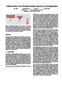
For haptic display using a point probe, we can specialize the algorithm based on OBBTrees by only testing a line segment (representing the path swept out by the probe between two successive steps) and an OBBTree. (The original algorithm [16] uses a overlap test between a pair of OBBs and can take more than 200 operations per test.) At run time, most of the computation is spent in nding collisions between a line segment and an OBB. To optimize this query, we have designed a very fast overlap test between a line segment and an OBB, that takes as few as 6 operations and only 36 arithmetic operations in the worst case, not including the cost of transformation. Here we describe this specialized overlap test between a line segment and an oriented bounding box for haptic rendering. Without loss of generality, we choose the coordinate system centered on and aligned with the box { so the problem is transformed to an overlap test between a segment and a centered axis-aligned bounding box. Our overlap test uses the Separating-Axis Theorem described in [16], specialized for a line segment against an OBB. Speci cally, the candidate axes are the three box face normals (which are aligned with the coordinate axes) and their cross-products with the line segment's direction vector. We project both the box and the segment onto each of these six candidate axes, and test whether the projection intervals overlap. If the projections are disjoint for any of the six candidate axes, then the segment and the box are disjoint. Otherwise, the segment and the box overlap. How are the projection intervals computed? First note that the center points of the segment and of the box project to the midpoints of their respective intervals as shown in Figure 1. We can also directly compute the lengths (actually the half-lengths) of the intervals. The intervals overlap if and only if the separation between their midpoints is less than the sum of their halflengths. Given a direction vector v of a line through the origin, and a point p, let the point p be the axial projection of p onto the line. The value dp = v � p=jvj is the signed distance of p from the origin along the line. Now consider the line segment with midpoint m and endpoints m + w and m ? w. The half-length of the line segment is jwj. The image of the segment under axial projection is the interval centered at ds = v � m=jvj and with half-length Ls = jw � vj=jvj 0
0
Given a box centered at the origin, the image of the box under axial projection is an interval with midpoint at the origin. Furthermore, if the box has thicknesses 2tx; 2ty ; and 2tz along the orthogonal 8
unit directions ux; uy ; and uz , the half-length of the interval is given by
Lb = jtxv � ux=jvjj + jty v � uy =jvjj + jtz v � uz =jvjj With the intervals so expressed, the axis v is a separating axis if and only if (see Figure 1) jds j > Lb + Ls m-w
m Ls Lb c
m+w
ds
Fig. 1. Overlap test between a line segment and an OBB
If we assume that the box is axis-aligned, then ux = [1; 0; 0]T ; uy = [0; 1; 0]T ; and uz = [0; 0; 1]T , and the dot products with these vectors become simple component selections. This simpli es the box interval length computation to
Lb = jtxvxj + jty vy j + jtz vz j Now, recall that the candidate axis v is either a box face normal, or a cross product of a face normal with the line segment direction vector. Consider the former case, when v is a box face normal, for example [1; 0; 0]T . In this case, the components vy and vz are zero, and the component vx is one, and we are left with Lb = tx The projection of the line segment onto the x?axis is also simple:
Ls = jwxj So, the test for the v = [1; 0; 0]T axis is
jmxj > tx + jwxj 9
The tests for the candidate axes v = [0; 1; 0]T and v = [0; 0; 1]T have similar structure. The three cases where v is a cross product of w with one of the box faces are a little more complex. Recall that in general,
Lb = jtxv � uxj + jty v � uy j + jtz v � uz j For the sake of concreteness, we will choose v = w � uy . Then this expression becomes
Lb = jtx(w � uy ) � uxj + jty (w � uy ) � uy j + jtz (w � uy ) � uz j Application of the triple product identity (a � b) � c = (c � a) � b yields
Lb = jtx(uy � ux) � wj + jty (uy � uy ) � wj + jtz (uy � uz ) � wj All of these cross products simplify, because the u vectors are mutually orthogonal, ux � uy = uz ; uy � uz = ux; and uz � ux = uy , so
Lb = jtx(?uz ) � wj + jty (0) � wj + jtz (ux) � wj And again, using the fact that ux = [1; 0; 0]T , and so forth,
Lb = txjwz j + tz jwxj The half-length of the segment interval is
Ls = jw � (w � uy )j = juy � (w � w)j = juy � 0j = 0 which is what we would expect, since we are projecting the segment onto a line orthogonal to it. Finally, the projection of the segments midpoint falls at
ds = (w � uy ) � m = (m � w) � uy = mz wx ? mxwz which is just the y?component of m � w. The nal test is
jmz wx ? mxwz j > txjwz j + tz jwxj Similar derivations are possible for the cases v = w � ux and v = w � uz . 10
Writing out the entire procedure, and precomputing a few common subexpressions, we have the following pseudo code:
let X = jwxj let Y = jwy j let Z = jwz j if jmxj > X + tx return disjoint if jmy j > Y + ty return disjoint if jmz j > Z + tz return disjoint if jmy wz ? mz wy j > ty Z + tz Y return disjoint if jmxwz ? mz wxj > txZ + tz X return disjoint if jmxwy ? my wxj > txY + ty X return disjoint otherwise return overlap When a segment and an OBB are disjoint, the routine often encounters an early exit and only one (or two) out of the six expressions is executed. Total operation count for the worst case is: 9 absolute values, 6 comparisons, 9 add and subtracts, 12 multiplies. This does not include the cost of transforming the segment (i.e. 36 operations) into a coordinate system centered and aligned with the box.
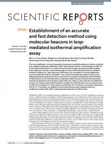
4 Implementation Issues H-COLLIDE, a framework for fast and accurate collision detection for haptic interaction, is designed based on the hybrid hierarchical representation and geometric algorithmic techniques described above. Figure 2 shows the system architecture of H-COLLIDE. H-COLLIDE has been successfully implemented in C++. We have interfaced H-COLLIDE with GHOST, a commercial software developer's toolkit for haptic rendering, and used it to nd surface contact points between the probe of a PHANToM arm and large geometric models (composed of tens of thousands of polygons). Here we describe some of the implementation issues. 11
Compute hybrid hierarchial representation
offline online
Input last position and current position / SCP Check contact witness false
true
Find segment’s bounding grid cell(s) Query cell’s OBBTree(s) Check potential triangles for intersection
return FALSE or intersection point / SCP
Fig. 2. The System Architecture of H-COLLIDE
4.1 Hashing Scheme
Clearly it is extremely ine�cient to allocate storage for all the cells, since a polygonal surface is most likely to occupy a very small fraction of them. We use a hash table to alleviate the storage problem. From each cell location at (x; y; z) and a grid that has len cells in each dimension, we can compute a unique key using
key = x + y � len + z � len2. In order to avoid hashing too many cells with the same pattern into the same table location we compute the actual location for a grid cell in the hash table with
TableLoc = random(key)%TableLength. Should the table have too many cells in one table location, we can simply grow the table. Hence, it is possible to determine which triangles we need to check in constant time and the amount of storage required is a constant factor (based on the grid grain) of the surface area of the object we want to \feel". Determining the optimal grid grain is a non-trivial problem in practice. We present a possible analytical solution to this issue and an accompanying anal12
ysis in the next section. Due to the practical di�culty of determining the optimal grid size, we simply set the grain of the grids to be the average length of all edges multiplied by a constant, which is chosen based on experimentation. If the model has a very irregular triangulation it is possible that there could be a large number of small triangles in a single grid cell. In this case, the triangles of each grid cell are stored in an OBBTree and checked for collision with the probe using the specialized overlap test described in Section 3.3. 4.2 User Options
Since the hybrid approach used in H-COLLIDE has a higher storage requirement than either individual technique alone, the system also allows the user to select a subset of the techniques, such as the algorithm purely based on OBBTrees, to allow for better performance on a machine with less memory.
5 Algorithm Analysis In this section, we examine the runtime performance of our hybrid collision detection algorithm for haptic interaction and analyze the issues involved in determining an optimal grid size. 5.1 Runtime Performance
Our algorithmic framework should be able to ensure that the running time of our approach is empirically constant, independent of the complexity of the model. Here we analyze the runtime performance of our hybrid approach, given a set of assumptions. Later in Section 6, we will see the results of relaxing some of our assumptions. Let P be a general polygonal model representing the environment in R3 . P may not have topological connectivity. Suppose that P is given as a collection of N triangles.
Assumption 1 The last probe location is close to the current probe location such that the path swept out by the probe goes through at most S grid cells, where S � 1. Assumption 2 P is uniformly tessellated, e.g. the number of triangles per unit surface area is constant across the surface of P .
13
Assumption 3 There is only one contact point with the surface of the object
and one triangle in contact with the probe, since it is only the tip of the probe that is touching the surface of the virtual object.
Assumption 4 The environment is stationary and rigid. Assumption 1, 3 and 4 are made based on conditions often encountered in haptic rendering. Assumption 1 is normally true due to the fast update rate required for haptic display. However, Assumption 2 is not always true, especially when P is a CAD model imported into a virtual environment. However, many scanned models have uniform triangle distribution over the surface of the model. In these cases, Assumption 2 is reasonable.
Lemma 5 Querying a preconstructed OBBTree of the model P for possible intersections with a line segment L takes O(KH ) time, where H is the height of a given precomputed OBBTree of P and K is the number of intersections between L and P .
An OBBTree is a binary search tree with an OBB stored at each node of the tree. If the height of the OBBTree for a model P of N triangles is H and each OBB-line overlap test described in Section 3.3 takes O(1). Therefore, querying an OBBTree takes O(H ) time for each intersection. If there are K intersection, then it takes O(KH ) time. Normally K = 1 given Assumption 3 in the case of haptic interaction using a three-degree-of-freedom force feedback device. And, the height of an OBBTree is O(logN ) in general, but it can be O(N ) in the worst case.
Theorem 6 Let N be the number of triangles in a given model P . With As-
sumptions 1 and 2, the expected collision query time using the hybrid data structures for possible intersections between P and a line segment L is O(1).
The basic dictionary operations using hash tables require only O(1) time on average [12] and this is extended for the point location problem [34]. There are typically less than two such queries, since S � 1 given Assumptions 1 and 4. So, we can query the hash table as to which OBBTrees need to be checked in expected O(1) time. According to Lemma 5, querying an OBBTree for intersection with L takes O(KH ) time, where H is the maximum height of the OBBTree per grid cell and K is the number of the intersections. H is O(logM ) for most cases and O(M ) in the worst case. During the o�-line computation, if the number of grid cells is G, we can bound the maximum number of triangles M per grid cell to be a small constant compared to the total number of triangles N in the model P , given Assumption 2. M can be computed by nding the maximum number of triangles per grid cell. We can also increase the number of grid cells G for larger models to obtain a constant bound on M . And, K � M . (With Assumption 3, K = 1.) Therefore, the 14
overall expected running time of our hybrid approach is O(1). 5.2 Determining the Optimal Grid Size
Even with the hashing scheme, a very small grid size can consume a huge amount of memory. Furthermore, if the granularity of the grid is extremely small compared with the size of a triangle, then it can take a long time to scan that triangle into all of the grid cells it covers. (However, this is a one-time precomputation when we load the model.) Similarly, a grid size that is too large can result in too many triangles to check for intersection in one force update iteration. Many models we encounter do not have polygons of uniform sizes. Many have long and skinny triangles. To analytically determine the optimal grid size is a rather di�cult problem, since there are numerous parameters that may a�ect the performance of any real-time haptic systems in addition to algorithmic issues. In order to simplify the model of computation to obtain a better intuition of the problem, we make Assumptions 1 { 4 in our analysis. With this set of assumptions, let N be the total number of triangles for the object to be \felt" by the probe, M be the average number of triangles per optimal grid cell, K = 1 and S = 1. We will analyze the bounds on the number of triangles that should be contained per optimal grid cell, and determine the optimal grid size based on these numbers. Let the cost of performing collision detection using only OBBtrees and specialized OBB-line overlap test be Cr, the cost of performing collision detection using hashing scheme alone be Cg , and the cost of using the hybrid algorithm be Ch . Let Cobb be the number of arithmetic operations required to perform an OBB-line overlap test, Ctri be the number of operations required to perform a line and a triangle intersection test, and Cl be the number of operations required to perform the hash function evaluation for table lookup. Since the total number of nodes in an OBBTree of height h is 2 � h + 1, we have
Cr = (2 log N + 1) � Cobb + Ctri Cg = M � Ctri + Cl Ch = (2 log M + 1) � Cobb + Ctri + Cl
(1) (2) (3)
For the hybrid method to outperform both the specialized algorithm with only OBBTrees or the uniform spatial partitioning using hash table look-up, (1) Ch < Cr and (2) Ch < Cg must be satis ed. Together (1) and (2) imply the following: 15
M < p N Cl ( 2) Cobb M > 2 � log M � CCobb + (1 + CCobb ) tri
tri
(4) (5)
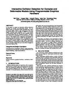
M is bounded above and below by these two inequalities. Inequality 4 is almost always true, when we assume that M is much smaller than N . Inequality 5 states that as M increases over some minimum threshold value the inequality is better satis ed. This implies that the hybrid algorithm will only be more ef cient than the specialized algorithm using the OBBTrees alone, if the average number of triangles per grid is greater than some constant. In our implementation, Ctri varies from 18 to 55 operations and Cobb varies from 42 to 72 (including the cost of transformation), since both tests have a sequence of conditional statements that may not be executed all the time depending the contact con guration. Cl depends on the number of operations taken by the random number generator. For the purpose of this analysis, we will assume Cl to be in the range of 10 ? 20 arithmetic operations. So, the ratios CCobbl and CCobb ranges from 0:9 ? 5:5 and 0:764 ? 4:0 respectively. This tri makes it rather di�cult to determine one unique value for the optimal grid cell for all scenarios { even under the given set of assumptions, though in theory we can compute a range of near-optimal grid sizes based on these assumptions. Let us now examine the impact of our assumptions on the computation of grid size. If Assumption 1 and 3 are not entirely true, e.g. the line segment swept out by the probe occupies multiple grid cells or there are multiple triangles intersecting the line segment, then small constants will be introduced to various terms in Eqns. (1), (2) or (3). If parts of the objects or the objects themselves start to move around, then we will also need to consider the cost of updating the data structures, which may vary depending on which part of models need to be checked for collision detection. Assumption 2 is not always true in many of the CAD/CAM models. Several real-world models we have observed and used in our benchmark (see Plates I-V) have uneven surface tessellations. In fact, their triangle shapes and sizes vary. Many long and skinny triangles each cover several grid cells; while grid cells of a di�erent part of the same model may have many small triangles. It is rather challenging to analytically compute one near-optimal grid size that actually works well in practice for all input models. 16
6 Performance and Comparison For comparison, we have implemented adaptive grids, our hybrid approach and an algorithm using only OBBTrees and the specialized overlap test described in Section 3.3. We have applied them to several models of varying complexity (see Color Plates at http://www.cs.unc.edu/~geom/HCollide/model.pdf or the images attached to the end of the paper). Their performance varies based on the models, the con guration of the probe relative to the model, machine con guration (e.g. cache and memory size), and the combination of techniques used by our system. Our hybrid approach results in a factor of 2-20 speed improvement as compared to a native GHOST method for the models we have tried. For a number of models composed of 5; 000 ? 80; 000 polygons, our system is able to compute all the contacts and response at rates higher than 1000 Hz on a 400MHz Pentium II. 6.1 Obtaining Test Data
We rst obtained the test data set by deriving a class from the triangle mesh primitive which comes with SensAble Technologies' GHOST library, version 2.0 beta. This records the start and the endpoint of each segment used for collision detection during a real force-feedback session with a 3-DOF PHANToM arm. We then implemented the three techniques mentioned above to interface with GHOST for comparison with a native GHOST method, and timed the collision detection routines for the di�erent libraries using the data from the test set. The test set for each of these models contains 30,000 readings. In order gain a better comparison between the di�erent techniques, the frameto-frame coherence method described in Section 3.2 was not used for these timings. The distinction between a collision and an intersection shown in the tables is particular to GHOST's haptic rendering. Each haptic update cycle contains a \collision" test to see if the line segment from the last position of the PHANToM probe to its current position has intersected any of the geometry in the haptic scene. If there has been a collision, then the intersected primitive suggests a surface contact point for the PHANToM probe to move towards. In this case it is now necessary to perform an \intersection" test to determine if the line segment from the last position of the PHANToM probe to the suggested surface contact point intersects any of the geometry in the scene (including the primitive with which there was a \collision"). The timings (in milliseconds) shown in Tables 1-5 were obtained by replaying the test data set on a four-processor 400 MHz PC, with 1 GB of physical memory. Each timing was obtained using only one processor. For comparison, 17
Table 1 Timings in milliseconds for Man Symbol, 5K triangles Method Adapt Grid Hybrid OBBTree GHOST Ave Col. Hit Worst Col. Hit Ave Col. Miss Worst Col. Miss Ave Int. Hit Worst Int. Hit Ave Int. Miss Worst Int. Miss
Ave. Query
0.0122 0.157 0.00964 0.0753 0.0434 0.108 0.0330 0.105 0.019
0.00883 0.171 0.00789 0.0583 0.0467 0.102 0.0226 0.141 0.014
0.0120 0.0800 0.00856 0.0683 0.0459 0.0793 0.0261 0.0890 0.017
0.0917 0.711 0.0217 0.663 0.0668 0.100 0.0245 0.364 0.048
Table 2 Timings in milliseconds for Man with Hat, 7K triangles Method Adapt Grid Hybrid OBBTree GHOST Ave Col. Hit 0.0115 0.0185 0.0109 0.131 Worst Col. Hit 0.142 0.213 0.138 0.622 Ave Col. Miss 0.0104 0.00846 0.0101 0.0176 Worst Col. Miss 0.0800 0.0603 0.0813 0.396 Ave Int. Hit 0.0583 0.0568 0.0652 0.0653 Worst Int. Hit 0.278 0.200 0.125 0.233 Ave Int. Miss 0.0446 0.0237 0.0349 0.0322 Worst Int. Miss 0.152 0.173 0.111 0.287 Ave. Query 0.030 0.025 0.028 0.070
we ran the same suite of tests on a single processor 300 MHz Pentium Pro with 128 MB memory. The hybrid approach appeared to be the most favorable on this system as well. 6.2 Comparison between Algorithms
Since the algorithms run on a real-time system, we are not only interested in the average performance, but also the worst case performance. Tables 1-5 show the timings in milliseconds obtained for both cases on each model and each contact con guration. 18
Table 3 Timing in milliseconds for NanoSurface, 12K triangles Method Adapt Grid Hybrid OBBTree GHOST Ave Col. Hit Worst Col. Hit Ave Col. Miss Worst Col. Miss Ave Int. Hit Worst Int. Hit Ave Int. Miss Worst Int. Miss
Ave. Query
0.0138 0.125 0.00739 0.0347 0.0428 0.0877 0.0268 0.0757 0.022
0.0101 0.168 0.00508 0.0377 0.0386 0.102 0.0197 0.0697 0.016
0.0134 0.0663 0.00422 0.0613 0.0447 0.0690 0.0213 0.0587 0.039
Table 4 Timings in milliseconds for Bronco, 18K triangles Method Adapt Grid Hybrid OBBTree Ave Col. Hit 0.0113 0.00995 0.0125 Worst Col. Hit 0.136 0.132 0.177 Ave Col. Miss 0.0133 0.00731 0.0189 Worst Col. Miss 0.128 0.0730 0.137 Ave Int. Hit 0.0566 0.0374 0.609 Worst Int. Hit 0.145 0.105 0.170 Ave Int. Miss 0.0523 0.0225 0.0452 Worst Int. Miss 0.132 0.133 0.167 Ave. Query 0.027 0.014 0.028
0.332 0.724 0.0109 0.210 0.0851 0.175 0.0545 0.284 0.18 GHOST 0.104 0.495 0.0280 0.641 0.0671 0.293 0.0423 0.556 0.048
First of all, we noticed that our analysis of expected constant time performance for our hybrid collision detection algorithm is validated empirically with the timings given in Tables 1-5. With an exception of average query time for Table 2 where Assumptions 1 and 2 do not hold, the average query time was consistently in the range of 0:014 to 0:016 milliseconds, independent of the complexity of the model. In comparison, the average query time for native GHOST collision detection ranged from 0:048 ? 0:32 milliseconds, as the model size increased from 5K polygons to 79K polygons. Note that even with incoherent motions and varied triangle distribution, the average query time in Table 2 (0.025 milliseconds) is still well within the operational range of 1 millisecond desired by haptic display. 19
Table 5 Timings in milliseconds for Butter y, 79K triangles Method Adapt Grid Hybrid OBBTree GHOST Ave Col. Hit Worst Col. Hit Ave Col. Miss Worst Col. Miss Ave Int. Hit Worst Int. Hit Ave Int. Miss Worst Int. Miss
Ave. Query
0.0232 0.545 0.00896 0.237 0.228 0.104 0.258 0.0544 0.030
0.0204 0.198 0.00405 0.139 0.0659 0.138 0.0279 0.131 0.016
0.0163 0.100 0.00683 0.121 0.0704 0.103 0.0256 0.0977 0.016
1.33 5.37 0.160 3.15 0.509 1.952 0.229 3.28 0.320
All of our algorithms are able to perform collision queries at rates faster than the required 1000 Hz force update rate for all the models we tested in the worst case. Although the hybrid approach often outperforms the algorithm based on OBBTrees, it is sometimes slightly slower than the algorithm based on OBBTrees. We conjecture that this behavior is due to the cache size of the CPU (independent of the memory size) and memory paging algorithm of the operating system. Among techniques that use hierarchical representations, cache access patterns can often have a dramatic impact on run time performance. The hybrid approach requires more memory and is likely to have a less cachefriendly memory access pattern than the algorithm purely based on OBBTrees, despite the fact that both were well within the realm of physical memory available to the machine. Furthermore, by partitioning polygons into groups using grids, the hybrid technique can enable real-time local surface modi cation. The adaptive grids-hashing scheme, a commonly used technique in ray-tracing, did not perform equally well in all cases. Once again, our hypothesis is that its inferior worst case behavior is due to its cache access patterns, in addition to its storage requirements. While the native GHOST method is competitive for the smaller model sizes, its performance does not scale as well for larger models. Our hybrid approach and our algorithm purely based on OBBTrees and the specialized overlap test appear to be relatively una�ected by the model complexity. 20
6.3 Dealing with Deformations
The algorithmic framework of our collision detection system can also handle local deformation. Based on our prototype system implementation of H-Collide [18], we developed an interactive multiresolution modeling and 3D painting system using a haptic interface, called inTouch [17]. The contact information output by H-Collide is used for both model editing and painting. The data structure of H-Collide allows local modi cation of data structures easily and enables fast model deformation at interactive rates. Although the environment (in this case the model being deformed and reshaped) of inTouch is no longer static and Assumption 4 does not hold, H-Collide is still able to keep up with the kHz haptic update rates.
7 Conclusion We have presented a fast and accurate collision detection algorithm for haptic interaction with polygonal models and a resulting system, H-COLLIDE, consisting of a suite of algorithms and a software implementation. The algorithmic design may be extended to support a future 6-DoF haptic devices to perform collision tests between a pair of 3D objects. In addition, it can be combined with the tracing algorithm [41] to handle complex sculptured models more e�ciently, using their control points. Our ultimate goal is to support haptic interaction with complex CAD models for virtual prototyping applications. We plan to continue studying the cache behavior of the hierarchical representations, to design new hierarchy construction methods to allow even faster local modi cation of surfaces, and to work on seamless integration of algorithmic techniques and data structures to support a wide range of haptic devices.
Acknowledgements: We are grateful to Army Research O�ce,
National Science Foundation, National Institute of Health National Center for Research Resources and Intel Corporation for their support and the reviewers for their comments.
References [1] J. Arvo and D. Kirk. A survey of ray tracing acceleration techniques. In An Introduction to Ray Tracing, pages 201{262, 1989.
21
[2] R. S. Avila and L. M. Sobierajski. A haptic interaction method for volume visualization. Proceedings of Visualization'96, pages 197{204, 1996. [3] D. Bara�. Curved surfaces and coherence for non-penetrating rigid body simulation. ACM Computer Graphics, 24(4):19{28, 1990. [4] G. Barequet, B. Chazelle, L. Guibas, J. Mitchell, and A. Tal. Boxtree: A hierarchical representation of surfaces in 3D. In Proc. of Eurographics'96, 1996. [5] N. Beckmann, H. Kriegel, R. Schneider, and B. Seeger. The r*-tree: An e�cient and robust access method for points and rectangles. Proc. SIGMOD Conf. on Management of Data, pages 322{331, 1990. [6] Frederick P. Brooks, Jr., Ming Ouh-Young, James J. Batter, and P. Jerome Kilpatrick. Project GROPE | Haptic displays for scienti c visualization. In Forest Baskett, editor, Computer Graphics (SIGGRAPH '90 Proceedings), volume 24, pages 177{185, August 1990. [7] S. Cameron. Approximation hierarchies and s-bounds. In Proceedings. Symposium on Solid Modeling Foundations and CAD/CAM Applications, pages 129{137, Austin, TX, 1991. [8] Stephen Cameron. A comparison of two fast algorithms for computing the distance between convex polyhedra. IEEE Transactions on Robotics and Automation, 13(6):915{920, December 1996. [9] J. Cohen, M. Lin, D. Manocha, and M. Ponamgi. I-Collide: An interactive and exact collision detection system for large-scale environments. In Proc. of ACM Interactive 3D Graphics Conference, pages 189{196, 1995. [10] J. E. Colgate and J. M. Brown. Factors a�ecting the Z-width of a haptic display. IEEE Conference on Robotics and Automation, pages 3205{3210, 1994. [11] J. E. Colgate and et al. Issues in the haptic display of tool use. Proceedings of the ASME Haptic Interfaces for Virtual Environment and Teleoperator Systems, pages 140{144, 1994. [12] T. H. Corman, C. E. Leiserson, and R. L. Rivest. Introduction to Algorithms. McGraw-Hill, 1992. [13] M. Finch, M. Falvo, V. L. Chi, S. Washburn, R. M. Taylor, and R. Super ne. Surface modi cation tools in a virtual environment interface to a scanning probe microscope. In Pat Hanrahan and Jim Winget, editors, 1995 Symposium on Interactive 3D Graphics, pages 13{18. ACM SIGGRAPH, April 1995. [14] S. Gibson. Beyond volume rendering: Visualization, haptic exploration, an d physical modeling of element-based objects. In Proc. Eurographics workshop on Visualization in Scienti c Computing, pages 10{24, 1995. [15] E. G. Gilbert, D. W. Johnson, and S. S. Keerthi. A fast procedure for computing the distance between objects in three-dimensional space. IEEE J. Robotics and Automation, vol RA-4:193{203, 1988.
22
[16] S. Gottschalk, M. Lin, and D. Manocha. ObbTree: A hierarchical structure for rapid interference detection. In Proc. of ACM Siggraph'96, pages 171{180, 1996. [17] A. Gregory, S. Ehmann, and M. C. Lin. inTouch: Interactive multiresolution modeling and 3D painting with a haptic interface. Technical report, Department of Computer Science, University of North Carolina, 1999. [18] A. Gregory, M. Lin, S. Gottschalk, and R. Taylor. H-Collide: A framework for fast and accurate collision detection for haptic interaction. In Proceedings of Virtual Reality Conference 1999, 1999. [19] M. Held, J.T. Klosowski, and J.S.B. Mitchell. Evaluation of collision detection methods for virtual reality y-throughs. In Canadian Conference on Computational Geometry, 1995. [20] P. M. Hubbard. Interactive collision detection. In Proceedings of IEEE Symposium on Research Frontiers in Virtual Reality, October 1993. [21] D. Johnson and E. Cohen. A framework for e�cient minimum distance computation. IEEE Conference on Robotics and Automation, pages 3678{3683, 1998. [22] J. Klosowski, M. Held, Joseph S. B. Mitchell, K. Zika n, and H. Sowizral. E�cient collision detection using bounding volume hierarchie s of k-DOPs. IEEE Trans. Visualizat. Comput. Graph., 4(1):21{36, 1998. [23] J. Klosowski, M. Held, J.S.B. Mitchell, H. Sowizral, and K. Zikan. E�cient collision detection using bounding volume hierarchies of k-dops. In Siggraph'96 Visual Proceedings, page 151, 1996. [24] S. Krishnan, A. Pattekar, M. Lin, and D. Manocha. Spherical shell: A higher order bounding volume for fast proximity queries. In Proc. of Third International Workshop on Algorithmic Foundations of Robotics, pages 122{ 136, 1998. [25] E. Larsen, S. Gottschalk, M. Lin, and D. Manocha. Fast proximity queries with swept sphere volumes. Technical Report TR99-018, Department of Computer Science, University of North Carolina, 1999. [26] M. Lin and S. Gottschalk. Collision detection between geometric models: A survey. In Proc. of IMA Conference on Mathematics of Surfaces, 1998. [27] M.C. Lin and John F. Canny. E�cient algorithms for incremental distance computation. In IEEE Conference on Robotics and Automation, pages 1008{ 1014, 1991. [28] William Mark, Scott Randolph, Mark Finch, James Van Verth, and Russell M. Taylor II. Adding force feedback to graphics systems: Issues and solutions. In Holly Rushmeier, editor, SIGGRAPH 96 Conference Proceedings, Annual Conference Series, pages 447{452, 1996.
23
[29] T. M. Massie and J. K. Salisbury. The phantom haptic interface: A device for probing virtual objects. Proc. of ASME Hpatic Interfaces for Virtual Environment and Teleoperator Systems, 1:295{301, 1994. [30] W. McNeely, K. Puterbaugh, and J. Troy. Six-degree-of-freedom haptic rendering using voxel sampling. Proceedings of ACM SIGGRAPH'99, pages 401{408, 1999. [31] A. Nahvi, D. Nelson, J. Hollerbach, and D. Johnson. Haptic manipulation of virtual mechanisms from mechanical cad designs. In Proc. of 1998 Conference on Robotics and Automation, pages 375{380, 1998. [32] B. Naylor, J. Amanatides, and W. Thibault. Merging BSP trees yield polyhedral modeling results. In Proc. of ACM Siggraph, pages 115{124, 1990. [33] M. Ouh-Young. Force Display in Molecular Docking. PhD thesis, University of North Carolina, Computer Science Department, 1990. [34] M. H. Overmars. Point location in fat subdivisions. Inform. Proc. Lett., 44:261{ 265, 1992. [35] S. Quinlan. E�cient distance computation between non-convex objects. In Proceedings of International Conference on Robotics and Automation, pages 3324{3329, 1994. [36] D.C. Ruspini, K. Kolarov, and O. Khatib. The haptic display of complex graphical environments. Proc. of ACM SIGGRAPH, pages 345{352, 1997. [37] K. Salisbury, D. Brock, T. Massie, N Swarup, and C. Zilles. Haptic rendering: Programming touch interaction with virtual objects. Proc. of 1995 ACM Symposium on Interactive 3D Graphics, pages 123{130, 1995. [38] H. Samet. Spatial Data Structures: Quadtree, Octrees and Other Hierarchical Methods. Addison Wesley, 1989. [39] Inc. SensAble Technologies. GHOST TM : Sofware developer's toolkit. Programmer's Guide, 1997. [40] R. M. Taylor, W. Robinett, V.L. Chii, F. Brooks, and W. Wright. The nanoManipulator: A virtual-reality interface for a scanning tunneling microscope. In Proc. of ACM Siggraph, pages 127{134, 1993. [41] T.V. Thompson, D. Johnson, and E. Cohen. Direct haptic rendering of sculptured models. Proc. of ACM Interactive 3D Graphics, pages 167{176, 1997.
24