architectures is modular and is based on simple cells, which leads to efficient .... arithmetic on large integers to residue arithmetic on smaller residue digits in.
226
IEEE TRANSACTIONS ON CIRCUITS AND SYSTEMS-11: ANALOG AND DIGITAL SIGNAL PROCESSING, VOL. 39, NO. 4, APRIL 1992
Fast and Flexible Architectures for RNS Arithmetic Decoding Khaled M. Elleithy, Member, IEEE, and Magdy A. Bayoumi, Senior Member, IEEE Abstract-An implementation of a fast and flexible residue decoder for residue number system (RNS)-based architectures is proposed. The decoder is based on the Chinese Remainder Theorem (CRT). It decodes a set of residues to its equivalent representation in weighted binary number system. This decoder is flexible since the decoded data can be selected to be either unsigned magnitude or 2's complement binary number. Two different architectures are analyzed; the first one is based on using carry-save adders (CSA's), while the other is based on utilizing modulo adders (MA). The implementation of both architectures is modular and is based on simple cells, which leads to efficient VLSI realization. The proposed decoder is fast; it has a time complexity of O(log N ) ( N is the number of moduli). Keywords-Residue number system, Chinese remainder theorem, modulo adder, carry-save adder, residue decoding, finite field algorithm.
number of bits and N is the number of moduli) is used to support only unsigned magnitude binary numbers. In [lo], the residue decoder is based on the base extension technique; it uses only modular look-up tables in its implementation. Since look-up tables are used, the choice of moduli must not be large for the implementation to be feasible. In addition, it does not support residue to 2's complement binary number system conversion. Although look-up tables are used in this scheme, its time complexity is O(N2).The implementation in [l 11 requires that one of the moduli must be a power of two; therefore, it may be limited in application. In [12], the proposed residue decoders are basically based on biased addition, and take advantage of the fast addition speed of CSA [16]. But the conversion output is not in 2's complement form. In [13] and [14], the scheme used has a time complexity of (?((log N ) 2 ) . In [15], the mixed-radix converI. INTRODUCTION sion algorithm is used with a time complexity of O(N). In this paper, a O(1og N ) residue decoder capable of ECENTLY, RNS has received increased attention due to its ability to support high-speed concurrent arithmetic decoding a set of residues to its equivalent representation in [11- [3]. Applications such as fast fourier transform, digital unsigned magnitude or 2's complement binary number sysfiltering, and image processing utilize the efficiencies of RNS tem is introduced. Two different architectures using CSA's arithmetics in addition and multiplication; they do not require based on [17] and modulo adders (MA's) [18] are implethe difficult RNS operations such as division and magnitude mented. In the following section, the RNS theory is recomparison. RNS has been employed efficiently in the imple- viewed. Section I11 discusses how this fast and flexible residue decoder can be implemented. Section IV evaluates mentation of digital signal processors [ 11, [4]. Since special purpose processors are associated with gen- the speed performance of this residue decoder. eral purpose computers, binary-to-residue and residue-to-biII. RESIDUENUMBER SYSTEM nary conversions become inherently important, and the conRNS, an integer, X , can be represented by an N-tuple In version process should not offset the speed gain in RNS of residue digits, operations. While the binary-to-residue conversion does not pose a serious threat to the high-speed RNS operations, the X = (r,,r2;.*,rN) residue-to-binary conversion can be a bottleneck. The Chiwith respect to a set of N moduli { m , , nese Remainder Theorem (CRT) [ 5 ] , [6] is considered the where ri = I X I mi, main algorithm for the conversion process. Several imple- m 2 , m N }. In order to have a unique residue representamentations of the residue decoder have been reported tion, the moduli must be pairwise relatively prime; that is, [7]-[15]. The residue decoders in [7] and [8] are based on fori # j . GCD(mi, m j ) = 1, using three moduli in the form (2" - 1, 2", 2" f 1); n is the number of bits. Due to the limitation imposed on the Then it is shown that there is a unique representation for each number of moduli and the choice of them, it is limited in number in the range of 0 5 X < IIE, mi = M where N is application. In [9], a scheme of O(1og N P ) (where P is the the number of moduli. The arithmetic operation on two integers A and B is Manuscript received October 15, 1990; revised December 17, 1991. This equivalent to the arithmetic operation on its residue represenwork was supported in part by NSF Grant MIP-8809811. This paper was tation, that is,
R
a ,
recommended by Associate Editor M. H. Etzel. K. M. Elleithy is with the Computer Engineering Department, King Fahd University, Dharan 31261, Saudi Arabia. M. A. Bayoumi is with the Center for Advanced Computer Studies, University of Southwestern Louisiana, Lafayette, LA 70504. IEEE Log Number 9 107521.
1057-7130/92$03.00 0 1992 IEEE
Authorized licensed use limited to: University of Bridgeport. Downloaded on February 24,2010 at 11:35:49 EST from IEEE Xplore. Restrictions apply.
ELLEITHY AND BAYOUMI: FAST AND FLEXIBLE ARCHITECTURES
221
complement binary number system, the following solutions where ” can be addition, subtraction, or multiplication. Therefore, it is desired to convert binary arithmetic on large are proposed. integers to residue arithmetic on smaller residue digits in 1) The number of modulo M adders or binary adders which the operations can be parallelly executed, and there is should be reduced to a minimum. no carry chain between residue digits. 2) CSA’s can be used wherever multi-operand addition is For applications in digital signal processing, it is helpful to required due to its high addition speed. define a dynamic range for the RNS with positive and 3) MA’s can be used for multi-operand addition due to negative integers. The dynamic range is defined as [ - ( M its constant speed in adding n-bit numbers in modulo 1)/2, (M - 1)/2] for M odd, and as [ - M / 2 , M / 2 - 11 M. for M even, or more specifically, for M odd, 4) Correction can be performed only at the last stage, and it supports conversion to both unsigned magnitude M- 1 and the 2’s complement binary number system. i f Z 5 7 ‘‘a
For ease of residue decoder design, it is partitioned into four stages as shown in Fig. 1. The input to the residue decoder are the residues and a control line, C which determines the output to be in unsigned magnitude or 2’s complement number system.
and for M even,
x=
[
M
ifZ 0, C,
N.
> 0 , and No 2 0, such
Authorized licensed use limited to: University of Bridgeport. Downloaded on February 24,2010 at 11:35:49 EST from IEEE Xplore. Restrictions apply.
ELLEITHY AND BAYOUMI: FAST AND FLEXIBLE ARCHITECTURES
229
2'-
M
2( 22n- M 0
''
-
2n- M
0 ''
means that output
is shifted l e f t with zero enterlna from the riaht
0 R c s u l t h l Rcsultlnl 5
5
Result11 5 1 Result11 c 1
(C) initial
As= 101111110111 Ac= 11001 1101 101 6,. 11I100010101 6,. 1010101 1001 1 f l - 2 0 5 0 , N - 12
Step 1
A.= 101 1 1 1 1 101 1 1 A.= 11001 1101 101 Bs. 111100010101 temp, = 10000000 1 1 1 1 temp2=Il 1 1 I I I I O ~ O I O
lOOOOOOOI I 1 1 1 1 1 I 1 1101010 8,; 1010101 1001 I
Step 2. temp,: temp,.
---________-_.
temp,= I101010101 IO t e m p 4 = I j 0 ~ 0 ~ o ~I o O~0~ Step 3. temp,= 1101010101 IO temp4= 0101010101 IO 2(2"-fl) = I 1 1 1 I I 1 1 1 100
----______----
temp,. 01 I I I I I I I100 temp,=[ 101010 101 100 Step 4. temp,. temp,.
01 1 1 1 I 1 1 1 100 101010101 100
Stage [log n l
Z " - f l = 011111I11110
Q, (Result
,
Result)c
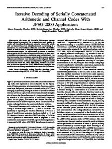
(e) Fig. 3.
(a) An example of partial sum adder for A06. @) A modulo sum adder. (c) Different stages of the modulo adder. (d) A detailed example for modulo addition. (e) Addition of partial products using modulo adders.
means that 1 = O(1og N ) .
that for all N 2 No the following is true: 1 C , log N I 7 *log N 1% 7
IC,
log N .
Case (2): O(l - 1) is odd, then
(7)
3*[?]
Then C , log N I I
IC,
log N V N 2 No.
= ?2O ( l -
1) - 1.5.
(8)
Possible values for C ,, C, , and No are 1, 2, 1. Equation (8)
O(l
- l ) m o d 2 = 1.
Authorized licensed use limited to: University of Bridgeport. Downloaded on February 24,2010 at 11:35:49 EST from IEEE Xplore. Restrictions apply.
230
IEEE TRANSACTIONS ON CIRCUITS AND SYSTEMS-11: ANALOG AND DIGITAL SIGNAL PROCESSING, VOL. 39, NO. 4, APRIL 1992
Algorithm Modulo-Add (A, B, Result)
Substituting in (3) using (9) and (lo), we get
;e([-
Input: Two variables A and B in modulo m , A is represented as A , and A,. B is represented as B, and B,. Since O(1) = 3, we can substitute in (11) to get successive ~ 1 variables 1 are bit numbers. values for O ( 1 ) as follows: Output: Variable Result represented as Result, and Result,. The relation between A , B , and Result is: Result O(2) = ; * 3 - 1. = IA+BIm. Procedure: ,9(3) = (512*3 - ( + ) ' * 3 -
e(,)
=
1) - ;.
(11)
;
begin Do in parallel begin Call Sum(temp,, A s , A,, B,) O ( 1 ) = ($)'-'*3 - (($)'-, + ($)'-, + + 1 ) *0.5 Call Carry(temp,, A,, A , , B,) end Do in parallel begin Call Sum(temp,, temp,, temp,, B,) = $($)' 1 . Call Carry(temp,, temp,, temp,, B,) end Suppose that the number of operands is N;then Case(temp2[ n 11 + temp, [ n + 11)of N = $(;)' + 1 . 0 : Do in parallel begin Using the same analytical method used for the case of even Result, := temp, e(,- 1) we can find constants C , , C2, and No e 0, such Result, := temp, that for all N 2 No the following is true: end exit 1 C , log N S -*log N IC, log N. I : Do in parallel 1% 2 begin Call Sum(temp,, temp,, temp,, (2" - m ) ) From the previous analysis in both cases 1 and 2, N numbers Call Carry(temp,, temp,, temp,, (2" - m ) ) can be added using CSA's in O(1og N ) . end 3.2.2 Implementation using Modulo Adder: The MA 2 : Do in parallel adder proposed in [ 181 is used to implement the partial sum begin adder. The idea of representing a number as a carry and a Cali Sum(temp,, temp,, temp,, 2*(2 - m)) sum borrowed from CSA can be used in the modulo addition to obtain a scheme that has a constant speed that does not Call carry( temp,, temp,, temp,, 2" (2 - m)) end depend on the number of bits. Basically, CSA depends not on end case the idea of completing the addition process at a certain stage, Case(temp, [ n + 13) of but postponing it to the final stage. In the intermediate stages, 0: Do in parallel numbers are represented as sum and carry to avoid the begin complete addition process. The MA is used to add two Result, := temp, numbers A and B in modulo m. Fig. 3(b) shows that A is Result, := temp, represented as a pair of numbers ( A , , A , ) , B is repreend sented as (B,, B,), and the output C is represented as (C,, exit C,). Each number is represented as a group of sum bits and I : Do in parallel carry bits. There is no unique representation for A , and begin A,. The condition that needs to be satisfied is Call Sum(temp,, temp,, temp,, (2" - m)) lAs+&Im= I A I m . Call Carry(temp,, temp,, temp,, (2" - m)) end One possible representation is end case A,= \ A I m ,A,=O. Case (temp, [ n + 11) of 0: Do in parallel We need to add four numbers ( A , , A , , B,, B,), which begin need two steps of CSA. After the addition process we need to Result, := temp, detect if - M or 2 * ( - M ) is required to adjust the result. Result, := temp, The adjusting process takes at most three steps. The proposed end algorithm for modulo m addition of two numbers can be I : Do in parallel described as follows. 8(4) = ( $ ) 3 * 3 - ( $ * 3
-
($*3
-
1
*
e
*
+
+
,
Authorized licensed use limited to: University of Bridgeport. Downloaded on February 24,2010 at 11:35:49 EST from IEEE Xplore. Restrictions apply.
23 1
ELLEITHY AND BAYOUMI: FAST AND FLEXIBLE ARCHITECTURES
U
begin Call Sum( temp,, temp,, temp,, (2" - M ) ) Call Carry(temp,,, temp,, temp,, (2" - M ) ) end Do in parallel begin Result, := temp, Result, := temp,, end end case end. Sum ( A , B, C , D ) begin Do in parallel (1 Ii In> A [ i ] := ( B [ i ]A C [ i ] V) ( B [ i ]A D [ i ] )V ( C [ i ]
Example: As an example, the modulo addition of A = 1272 and B = 450 for m = 2050 is shown in Fig. 3(d). There is no unique representation for A and B. One valid representation is shown in Fig. 3(d). Fig. 3(d) shows the detailed modulo addition operation for this example. In step 1 we get ternp2[13]= 1 , and in step 2 we get temp4[13]= 1 , which means that at step 3 we have to add 2(2" - M ) . At step 3 we get temp,[l3] = 1 , which means that at step 4 we have to add 2" - M . At step 4 we get temp,[l3] = 0, which means that the addition process stops at step 4. The result of step 4 is the final result. The proposed modulo adder has the following advantages. 1 ) It does not have any limitation on the size of the modulus. 2) It is quite modular; it is a 2-D array of one type cell (full-adder). 3) It is easy to pipeline. 4) It is very efficient architecture for the implementation of the CRT decoding and modulo multiplication [20].
AD[il>
end. Carry ( A , B , C , D ) begin A[1] := 0 Do in parallel (1 Ii In ) A [ i + 11 := B [ i ] @ C [ i ]@ D [ i ] end.
-
Theorem 3: Adding n numbers ( y l , y2, ulo M is equivalent to:
An implementation of the algorithm is shown in Fig. 3(c). Theorem 2: The modulo adder scheme for adding two n-bit numbers in modulo rn has an asymptotic time complexity 8 ( l ) . Proof: To prove that the number of steps is constant (five), we need to prove that the last carry is equal to zero in five or less steps. Induction is used to prove the correctness of the theorem on the number of bits n. Basis step: n = 0 means that we do not add any numbers and in this case the required number of steps is zero. Induction hypothesis: assume for a fixed arbitrary n 1 0 that the maximum number of steps is five. Induction step: for numbers with n 1 bits, let
+
7 = temp,[n
+ 11 + temp,[n + 21.
+
+
+
+
+
+
+ +
+
+ +
+
+
y,) in mod-
-
-
1 ) Adding ( y l , y2) modulo M , * , ( yi, yi+1), * , and (Yn-13 U,) gives Y 1 2 2 * * * 9Y ( n - 1 ) " . 2) Step 1 is repeated on ( y 1 2 , ~ ~ ~ - 1,( Y, ( ~. - ~ ) ( ~ - , ) , Y("- 1,"). 3 ) Step 2 is repeated for log lv] - 2 times to obtain one final output represented as a sum and carry.
1
Proof: To add two numbers a and b in modulo M we have the following cases: i)
ii)
a < M and b < M then a
I b 1 M , then:
=
l a l M and b
=
l a + b l , = Ia,+b,I,* (12) a>Mand b 2" then 2"+' - m < 2", which means that (2"" - m ) [ n ]= 0. The worst case is to have ternp,[n I ] and temp,[n 21 equal one. This means that temp,[n 11 = 0 and temp,[n 21 = 1, then temp,[ n 21 = 0. In this case the correction is done in two steps (step 3 and step 4). c) 7 = 2: then the correction is 2 * (2"+' - m ) in step 3. The worst case is temp,[n 11, temp4[n 21, and 2*(2"+' - m ) = 1 . Then temp,[n 13 = 1 , temp,[n 11 = 1 and 2"'l - M = 0. At step 4 temp,[n 11 = 0 and temp,[n 21 = 1. At step 5 temp,[n 11 = 1 and temp,,[n 21 = 0. In this case the correction is done in three steps (steps 3-5).
e ,
Since x (13):
IM+x+bl,=
M and b < M like case ii). > M and b > M then a = M
+ x and b = M
+ y , then:
l a + bJ,=
IM+x+M+yJ, = IX+YIM'
Ia,+b,l,.
(15)
From the previous four cases, Since addition is associative, then
I ~1 + ~2 + . *
*
+Yn
IM I._
Authorized licensed use limited to: University of Bridgeport. Downloaded on February 24,2010 at 11:35:49 EST from IEEE Xplore. Restrictions apply.
IEEE TRANSACTIONS ON CIRCUITS AND SYSTEMS-11: ANALOG AND DIGITAL SIGNAL PROCESSING, VOL. 39, NO. 4, APRIL 1992
232
Using (16) we have
We can further expand this expression using the same method to get the addition process in the right-hand side in terms of only two operands added in modulo M . Theorem 3 means that adding n numbers in modulo M can be performed using a binary tree consists of units that are capable of adding only two numbers in modulo M . MA’s are used as those building blocks to perform the addition process. Since MA requires that inputs be represented in the form of sum and carry, then this form should be enforced at all levels. The form will be enforced automatically for levels 2 2 , because the outputs of the previous levels are in the correct forin. For the first level we have the following:
Ti,= y,, Ti, = 0 v l
1 I
B’c
Fig. 4.
1
BC
’
Magnitude Compared
A
First set
1
M- 1
2
2M- 1
if M odd
Since each group if fed into a ROM module as an address input, the number of bits in each group should be small so that small ROM’s that are fast and occupy small silicon area are used to implement this level. However, the number of groups, g , should be kept to be as small as possible since the complexity of MC cells is a function of the number of ROM modules, g. Hence, there are trade-offs in choosing g and the number of bits in each group. The following discussion is divided into two parts: sign magnitude and 2’s complement. 3.3.1 Sign Magnitude: As shown in Fig. 4, the input to ith ROM module is G,, and the outputs are Bi’s and Ci’s. The function of this ROM module is depicted as follows:
1,
if G , > ( j M - 1);
0,
if G i + ( j M -
1,
ifG,= (jM- l),
for j = 1
A -1
for j
A -1
=
2
for i = 1 , 2 ; * - , g . The ROM modules compare the input pattern S to the first set of values in Table 11 and produce g * (2 A - 3) outputs that are fed to the MC level.
if M e v e n
-M_
M- 1
2 3M- 1
n-1
( n - l)M- 1
1
2 3M
--
1
2
L
(2n - 3 ) M - 1 2
The MC level consists of ( A - 1) MC cells. This level takes the input from ROM level and does further comparison. The function of the MC cells is determined by: ifS