Fast and robust pointing and tracking using a second generation star tracker John Leif Jørgensena and Andrew Picklesb a
Department of Automation, Technical University of Denmark and b Institute for Astronomy, University of Hawaiic ABSTRACT
Second generation star trackers work by taking wide-angle optical pictures of star fields, correlating the image against a star catalogue in ROM, centroiding many stars to derive an accurate position and orientation. This paper describes a miniature instrument (10cm cube), fast and lightweight (850g), including database and search engine. It can be attached to any telescope to deliver an accurate absolute attitude reference via a serial line. It is independent of encoders or control systems, and works whenever it can see the sky. Position update rates in the range of 1 to 5 Hz enable closed-loop operations. The paper describes the instrument operational principles, and its application as an attitude reference unit for a telescope. Actual data obtained at the University of Hawaii's 0.6-m telescope are presented, and their utility for correcting mechanical alignment discussed. The system has great potential as a positioner and guider for (i) remotely operated optical telescopes, (ii) infrared telescopes operating in dark clouds, and (iii) radio telescopes. Other application recommendations and the performance estimates are given. Keywords: Telescope pointing and guiding, optical, infrared, radio.
1. THE ADVANCED STELLAR COMPASS AND TELESCOPE GUIDING One problem common to Spacecraft and telescopes is the need for a rather precise attitude information during operation. For use on board spacecraft several attitude reference sources are available, e.g. the Earth horizon, direction towards the Sun, the Moon or other planets, and the stars. However, only the stars provide the necessary accuracy if an attitude estimate better than 30 arcseconds is required, and this has lead to the development of an instrument called a star tracker. Based on images of a part of the night sky, and the rotation from the star tracker camera coordinate system to the spacecraft reference system, the star tracker may provide attitude information for manoeuvres and stabilization of the spacecraft. The first generation of star trackers locked onto a few of the brighter stars in the Field Of View (FOV) and by continuously following these stars as they moved through the FOV, they were able to derive all three components of the rate of change of the attitude. The second generation star trackers, like the Advanced Stellar Compass which is described in this paper, detect all bright stars in the FOV, match the detections measured to a star catalogue and, based on the match found, derive the absolute attitude of the instrument. The operation of the first generation star tracker resembles the operation of guiders used on modern telescopes. In this case normally only the two components giving the pointing direction of the telescope are requested, as the telescope mount provides for a tight control of the motion about the boresight. Hence, a single accurately tracked star might suffice to provide the necessary attitude information to guide the telescope. Only for telescopes where the roll about the telescope barrel is requested more than one star have to be tracked. Star trackers offer accuracies comparable to what is achieved by star guiders and are
c
JLJ: Email
[email protected]; Tlf. +45 4525 3448 AP: Email
[email protected]; Tlf +1 808 969 7649
designed for use directly in closed control loops. Second generation star trackers provide such additional information as absolute pointing and roll status, and also guarantee attitude information at all directions as they are designed for full sky coverage. The latter feature is especially attractive in cases where no usable guide star is close to the object of interest in the FOV. As the star trackers are designed for use in space they often offer substantial autonomy, which may be advantageous if remote operation is called for. They can recover absolute pointing information even after normal servo systems have lost index calibration, as long as they can see the sky. The Advanced Stellar Compass described here, is a miniature second generation star tracker, and its operation and performance has been proven both by numerous tests at various telescopes as well as in space.
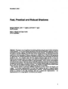
Figure 1, The dual camera head ASC.
2. THE ADVANCED STELLAR COMPASS INSTRUMENT DESCRIPTION The current version of the Advanced Stellar Compass (ASC) is an improved implementation of the instrument developed for the Danish Geomagnetic Research Satellite Ørsted. The Ørsted version was successfully tested in space onboard the NASA sounding rocket “Thunderstorm III”, that was launched September 2. 19951. The new version of the instrument was developed in order to further miniaturize the system, improve the update rate, the accuracy and the robustness. The functionality and performance of this version was first tested in space onboard the ESA test satellite TEAMSAT in September 1997. Two more instrumentswill accompany satellites to be launched in 1998: The Ørsted satellite and the Swedish micro-satellite ASTRID 2.
Figure 1, shows the version that is going to be integrated on the German CHAMP satellite in 1998. This instrument is equipped with two camera units, in order to increase the degree of freedom for attitude manoeuvres, especially on the day side of the Earth. As seen on the photo, the instrument consist of the camera heads units (CHU) and a control box dubbed the Data Processing Unit (DPU). The CHU’s are essentially low light CCD cameras, fitted with fast wide angle lenses. Long cables (up to 20m) between the CHU’s and the DPU carry the analogue video signal. One major benefit from splitting the instrument into two units is, that the impact from mounting the CHU close to the focal-plane of the main instrument is kept to a minimum. E.g. the power dissipation in each of the CHU’s is only 0.35W and its mass is less than 250g (including ionizing radiation shielding for space use). The low power dissipation in turn enables full performance without active cooling. The F/0.8 lens has a focal length of 20mm. This results in a FOV of approximately 18E x 12E, i.e., a relatively wide angle system. Each CHU measures only 50mm x 50mm x 45mm, including the lens. The DPU contains a stand alone computer, a power converter and a frame grabber. The computer consists of an AMD 486 processor, 4MB of RAM, 4MB of Flash Disk and support circuitry. The Flash Disk contains all necessary programs, data and star catalogues to perform the attitude determination. The DPU communicates with the user, e.g., the control loop computer, via an RS422 serial link. The use of a Flash memory for program storage enables remote updates to all of the software SW via the RS422 link. As the RS422 utilizes balanced drives, the cable between the DPU and the control computer may be several hundred metres. The power consumption of the DPU is 7.5W running on a 28V power supply, including secondary power generation for two CHU’s. In a spacecraft application the ASC is commanded via the control computer. On ground a program running on a PC may be used to interface to the instrument, a so-called Electronic Ground Support Equipment (EGSE). The EGSE contains the full set of commands and may be used to perform stand alone test, upload SW changes or settings and as a monitor during closed loop operations, e.g., on a telescope. The integration time of the CCDs is user selectable during operation, and may vary from 16sec to 1/16 of a second. The DPU is capable of processing up to 6 images per second enabling an update rate of 6Hz. Hence, one may get an attitude update rate of, either 3Hz driving two CHU’s, or 6Hz driving one CHU. The shorter integration times are intended to ensure operation during high speed attitude changes. The short integration time minimizes motion smear with some decrease in accuracy. The optimum attitude accuracy per update is achieved at 1Hz. But as some applications require a minimum update rate, the user may select to control the integration time via different schemes: A fixed integration time, autonomous switching whenever high attitude change rates are detected, or autonomous switching with a fixed minimum integration time. Normally the CCD gain and analog offset are controlled autonomously along with various system parameters, but in all cases the user may switch off the autonomy and take over the control via remote commands. The autonomous offset and gain control enables operation during non-optimal or anomalous conditions, e.g., as when stray light from dusk, dawn or the Moon enters the FOV. Several tests have been performed to verify the correct operation of the autonomy. E.g., nominal operation in situations with the Moon, clouds or artefacts in the FOV. Correct operation has been achieved even with the major part (70%) of the FOV obscured by a telescope roof. As shown below, the accuracy of a CHU is less for the attitude component giving the roll about the boresight than the accuracy for the pointing components of the boresight. An increased redundancy and a much higher degree of freedom for a spacecraft control system, are the reasons for using more than one camera head.
3. INSTRUMENT FUNCTIONALITY The ASC was developed for fully autonomous star tracker operations, tracking all brighter stars in the camera FOV. A brief description of the principle of operation of the ASC, the processes taking place from the image is read out of the CCD to the attitude data calculation and display, is described in sequence below.
The image is time stamped at the centre of integration. After integration, the image is read out of the CCD, passed through a correlated double sampler, line buffered, and transmitted to the DPU and digitized according to the current gain and offset values. When an entire image has been digitized, the image is passed to the CPU, that first performs centroiding of the stars in the image. During this operation, bright objects have to be detected, erased and removed from the list of centroids. Next step corrects for the distortions to the image introduced by the fast lens and large FOV, after which the image analysis function takes over. The image analysis functions performed on an image depend on several conditions. In normal operation, the attitude difference between two consecutive images is so small that the following procedure is adequate. Based on the previous attitude and the star catalogue, a star image is formed. The catalogue images and camera image are then matched, and a least squares fit is performed. The result of this process is the relativistic attitude. In a number of situations, for example after power cycling, after a Single Event Upset (SEU is the most frequent radiation impact on a computer), or following a series of invalid images (bright objects, etc.), the previous attitude is invalid or missing. In this case an extra image processing step, the initial attitude acquisition, is included. The centroid list is analysed for triplets of nearest and next nearest neighbours. The resulting set of triplets is then matched to a special version of the star catalogue also stored in the DPU, the star database. The entries in this star database consist of all conceivable triplets. Based on this match a crude attitude is obtained. This attitude is then used, in the consecutive processing, as a bias instead of the previous invalid attitude. In order to transform the relativistic attitude to heliocentric attitude, the velocity vector of the spacecraft or of the observatory relative to the heliocentric system is needed. In the instrument this vector is obtained, with the necessary precision, via the day of year and an orbit model. For space use, the orbit model needs to be updated at intervals from hours to days depending on the orbit-perturbing forces like air-drag. If the correction is required by a telescope user, the time has to be uploaded once after each power-cycle of the instrument. Typically, these updates are based on GPS data. The correction amounts to maximum 26 arcseconds for low Earth orbits. Apart from the attitude determination the software maintains a list of other functions, which may be divided into the following three categories: 1) Communication functions: An I/O queue for data to be sent (TM) and commands (TC). A dedicated debugging line for monitoring and closed-loop testing. System and housekeeping monitoring. 2) Supervisory functions: A SW-watchdog monitors the task switching and program execution. A hot-spot database that monitors the ageing and occasional radiation damages of the CCD-chip. A bit-washing function refreshing the Hamming-code protected memory at user-specified intervals. 3) Imaging functions: Automatic or user specified image acquisition, compression and TM. A Planetary feature-tracking module, and Non-stellar-object detection and tracking. Whereas the functions under 1 and 2 are related to the operating system of the instrument, the functions under 3 are meant to the ease the use and debugging of the instrument. The user may command the ASC to acquire, compress and transmit as many of the images processed for attitude determination as the data-link to the instrument allows. Also individual images may be acquired, compressed, stored and sent on command. The ASC may compress the images in the following ways: Uncompressed, Centroid list, Region Of Interest around bright objects or JPEG. The JPEG compression factor may be from lossless (1.5-2 times) to 100 times lossy compression. This feature may be used to give a remote user a fast overview of the current atmospheric condition. Because all brighter stars are identified, then objects which are detected but not matched to the star catalogue are sifted out by the program. At user request, a list of these objects may be attached to each attitude update. This list contains the pointing direction to the object and its magnitude. Objects hence tracked may be spacecraft, comets, galaxies, et cetera. Typical single frame accuracy of such an object is, say, 3 arcsecond at an approximate magnitude of mv 6. The user may choose to have the attitude measurement output in either right ascension, declination and roll, or in the form of a quaternion. The latter being the preferred format for Attitude and Orbit Control Systems (AOCS). The onboard star catalogue is corrected for proper motion, typically to the mid time of the mission, and the attitude is given in J2000.0 reference
coordinates. However, if the attitude is requested in Earth Centred Coordinates, the instrument may at user request correct for the Precession and Nutation too.
4. TELESCOPE MOUNTING AND GUIDING The relatively large FOV of the ASC imposes some constraints for the mounting on a telescope, if full performance is to be achieved. Firstly, obscuration by structures in the telescope building or on the telescopes must be avoided. This has to be ensured during any nominal motion or pose of the telescope. Secondly, reflected stray light from structures must be avoided. To suppress stray light a baffle is normally mounted. A baffle may, for telescope use, be a simple black painted cone of some 10cm’s length circumscribing the FOV. This is in contrast to the often complex and large multi-staged baffles used onboard spacecraft to enable operation on the day-side of the Earth. These constraints mean that the tracker either should be mounted on the telescope barrel or structure close to the upper end, or directly on the secondary mirror if possible as depicted in figure 2. A typical test mounting close to the end of the telescope barrel is seen in figure 3, where three CHU’s undergoing a joint test are mounted close together. As part of the test was to determine stray light impact none of the cameras were fitted with a baffle.
FOV
ASC
Figure 2, Mounting of the ASC on a telescope secondary mirror .
At nominal operation the attitude latency, i.e. the time from the centre of integration to the attitude is outputted to the user, is mainly governed by the integration time selected as the CCD’s are operated in free running mode to reduce readout noise. The data processing time consumption is 180ms per image on average, resulting in a total latency of 1.5 times the integration time plus 180ms. With an integration time of 0.25s, this results in a data latency of just 0.55s. Such a time lag introduces a time delay in a control loop, but as the time of centre of integration is output together with the attitude packet, the impact is limited to that of a pure time delay. Apart from the timing and attitude information, each attitude measurement contains the following status information. As the match is performed as a fit, the fit residual is a very powerful tool determining the quality of the current attitude estimate. If stray light, a passing aircraft or other noise sources have disturbed the image, the residual will increase, and at the point where the match is lost, the residual will rise abruptly. Hence the fit Figure 3, Three CHU’s mounted at the top end of the TMO 0.6m telescope. residual might both be used as a quality measure and as a detector for validity. Using the fit residual as a flag, the algorithm has been tuned to never indicate validity at a false attitude (i.e. false positive) and only rarely a false negative result which is especially important for closed loop operation. Also the number of stars used in the fit is listed, and on the occasion that an initial attitude acquisition (lost-in-space) is performed the number of triplets correctly
matched is output. To enable an accurate time stamp operation the instrument might be connected to a GPS, either via the control computer or via the EGSE. In case that GPS time and position are available, the ASC automatically synchronises the internal clock to GPS time with an accuracy better than 0.5ms. The GPS position and velocity data are linked with the time used to initialize the calculation of the current heliocentric velocity. In the case that no GPS information is available, the user might choose to upload the timing and position data directly.
5. TEST AND VERIFICATION In order to assess the performance of the ASC under the most realistic conditions, a series of tests were performed in July and August 19972. The tests were performed partly at the 0.6m telescope at Table Mountain Observatory (TMO) near Wrightwood in California, partly at the 0.6m and 2.2m telescope at Mauna Kea (MK) in Hawaii. TMO is a facility operated by the Jet Propulsion Laboratory, whereas the 0.6m and the 2.2m telescopes at Mauna Kea are operated by IFA, University of Hawaii. Because the main purpose of the tests were to assess the ASC performance, three CHU’s labelled A, B and FS respectively, were mounted simultaneously. The relative boresight orientations could be changed as indicated in Figure 4. By changing the angle between the boresight, operation at different parts of the night sky was achieved, whereas a co-boresighted operation is useful for extracting system noise etc.. Table 1 lists the various tests as well as the main objective for each test.
Series/Name TMO4-1 TMO4-2 TMO4-3 TMO4-4 TMO4-5 TMO4-6 TMO4-7 TMO4-8 TMO4-9 TMO4-10 MK24-A MK24-B MK24-C MK24-D MK24-E MK24-F MK24-G MK24-H MK24-I MK24-J MK24-K MK24-L MK88-A MK88-B MK88-C MK88-D MK88-E
Time (Date Local time) 19/7/1997 22.25-23.25 19/7/1997 23.55-0.30 20/7/1997 1.24-2.30 20/7/1997 21.33-22.33 20/7/1997 22.38-23.38 20/7/1997 23.46-23.52 20/7/1997 23.54-00.00 21/7/1997 00.01-00.06 21/7/1997 00.07-01.00 21/7/1997 01.01-02.00 1/8/1997 19.55-21.00 1/8/1997 21.00-23.00 1/8/1997 23.00-24.00 2/8/1997 20.18-22.53 2/8/1997 23.13-00.26 3/8/1997 00.36-00.46 3/8/1997 00.46-00.56 3/8/1997 00.56-02.45 3/8/1997 21.00-22.10 3/8/1997 22.12-23.25 3/8/1997 23.28-00.50 4/8/1997 00.50-02.30 4/8/1997 20.00-04.50 4/8/1997 00.16-00.45 4/8/1997 00.45-01.15 4/8/1997 01.15-01.45 4/8/1997 01.45-04.50
Table 1, Overview of test-series Telescope action Setup (Camera-grabber-pos. no.) Pointing A-A-1,B-B-4,FS-FS-2, no Baffle Tracking Do. 6-12x Sidereal rate Do. Pointing A-A-2,B-B-3,FS-FS-4, no Baffle Tracking Gain 400H Do. Tracking Gain 300H Do. Tracking Gain 200H Do. Tracking Gain 100H Do. Sweep near Moon A-A-2,B-B-3,FS-FS-4-Baffle Pointing Do. Pointing A-A-1,B-B-4,FS-FS-2, no Baffle Pnt. Galactic low –hi Do. Track. Galactic hi Do. Zenith Pointing Do. Tracking galactic hi A-A-3,B-B-2,FS-FS-4, no Baffle Pointing int-time test Do. Pointing int-time test Do. Pointing Jupiter Do. Pointing Galactic low A-A-3,B-B-1,FS-FS-4, no Baffle Pointing Galactic hi Do. FS-cam rotated 120° Tracking Galactic hi Do. Jupiter in-out of FOV A-A-3-Baffle,FS-FS-4 Tracking around 66N A-A-1,B-B-4,FS-FS-2, no Baffle Tracking around 68N A-A-2,B-B-4,FS-FS-1, no Baffle Tracking 0.5Hz Do. Tracking 0.25Hz Do. Tracking all sky Do.
Table 1, Overview of test-series Times in the table is given as local daylight saving (i.e. GMT – 10), which for, say, the MK24-I series gives a Julian date of approximately 2450664. The Moon was in its last quarter during the TMO tests and just new during the MK. As an example of the result of a typical test (MK24-K), some of the attitude data output from the three units is shown below. During this test the telescope was tracking., the FS camera was coboresighted with the telescope, and the camera A and B boresights 20E north and south of the telescope boresight respectively. In figure 5, the declination, right ascension and roll of the FS camera are shown. As the FS camera is almost co-boresighted with the telescope itself, the attitude essentially measures the actual attitude motion of the telescope itself.
Figure 4, The possible relative camera poses. 18.98 18.97 18.96 18.95
36"
18.94
The 0.6m telescope at Mauna Kea is a rather old telescope without inertial reference inputs to the control of the tracking mode. Furthermore, the equatorial mount had not been realigned after major changes to the telescope.
18.93 18.92 18.91 18.9 Time 1600 frames/1815sec.
As the attitude measurements shown in figure 5 through 7, all have been corrected for relativistic aberration and rotated to the true mean of day, all three components should have stayed constant assuming correct operation of the tracking function. Clearly, the declination exhibit a slope of some 0.12"/sec. Also, the right ascension and roll components exhibit trends. The most likely cause of this is a misalignment of the equatorial mount of some fraction of a degree. The trend in the roll component could also be caused by wear or unbalanced loading of the bearings. We tested the stability of the telescope barrel in order to get an estimate of the effect of wind loads. This test showed that the attitude changed some 4-5” for a 1kg transverse load at the bottom end of the telescope, and 30” for a load of 20kg . The right ascension component also displays another interesting feature. At a certain point in time, the tracking operation seems to drop in rate for 2-300 seconds, after which it picks up the rate Figure 5, Declination, Right Ascension and Roll measured by the FS again. The amplitude of the error thus induced in camera.
17.75
35.15
17.7125
35.1125
135"
135" 35.075
17.675
35.0375
17.6375
17.6
35
Time 669 frames/3600sec.
Time 669 frames/3600sec.
Figure 6, Declination measured by the Aand B cameras respectively. 304.14
288.66
304.13
288.65
304.12
288.64
36"
36" 304.11
288.63
304.1
288.62
304.09
288.61
304.08
288.6
Time 669 frames/3600sec.
Time 669 frames/3600sec.
Figure 7, Right ascension measured by the Aand B cameras respectively. the pointing is of the order of 30". This phenomenon is most likely due to sticktion in the horizontal drive. Figure 6, shows the declination components measured by the A and B cameras during the same test. These graphs confirm the slope found in the FS measurements. Please note, that these measurements were started simultaneous with the FS, but they proceed for 3600s. Figure 7, shows the right ascension components. The feature where the horizontal drive speed drops is clearly visible in both series. The trend is, however, quite different as measured by the two cameras. This is consistent with the size of measured roll about the boresight, and the fact that most of the trends found in the right ascension are due to a roll about the axis of the telescope barrel.
6. FIELD OF VIEW AND THE ATMOSPHERE The large field of view of the ASC creates a set of disadvantages as well as advantages compared to the moderate FOV of most telescopes. Obviously, the ASC will have a much greater chance to end up with a bright non-stellar object in its FOV during operation than what is the case for the telescope. However, as the ASC does not need more that a fraction of its FOV having high quality to provide high quality measurements, not even Venus or a passing aircraft are able to offset the measured attitude. The only luminous objects in the night sky, as seen from a telescope, bright enough to affect the accuracy are the Moon and moonlit clouds, e.g. high cirrus. In order to minimize the effect of such stray light, a baffle must be fitted in front of the camera. Figure 8 shows a camera head together with a baffle large enough
Figure 8, A camera unit next to a stray light suppression baffle.
to ensure full operation of the ASC, even with the Moon just next to the FOV (assuming an otherwise clear night sky). The effect generated by the Moon entering the FOV, is that the uneven background hence induced, will offset the centroiding for some of the stars. Because the ASC is equipped with an outlier rejecting filter skipping centroids that are too far off, the effect is limited. The fit residual will increase far above the average level, thus flagging the anomaly to the user or control loop. The averaging effectively performed by the least squares fit over all brighter stars in the FOV, has other attractive features than the one of increasing the accuracy. Typically, the single measurement noise is well below the seeing as measured by the telescope, as the light from each individual star in the ASC image arrives via rather different paths and, hence, has been subjected to different distortions. The net effect of this phenomenon is that even at moderate to poor seeing, a highly accurate tracking of the telescope may be achieved. For telescopes operating in the visual part of the spectrum, this may not be of much importance, but for other wavelengths the benefit may be substantial.
53.36 53.359 53.358
3.6" 53.357 53.356
As an example of this, a measurement 53.355 obtained at TMO (series 4-2) is shown in 53.354 Figure 9. The telescope was tracking, and Time 3487 frames/3954sec. according to the site astronomer the accuracy of the tracking operation had Figure 9, Attitude measurements obtained with telescope tracking, 1Hz data. just been verified to be less than 1arcsecond. The seeing was estimated to 53.36 be 2-3arcseconds throughout the measurement lasting about an hour. 53.359
The standard deviation of the data 53.358 shown in Figure 9 is 1.13arcseconds. This value includes the instrument Noise 53.357 Equivalent Angle (NEA), the telescope tracking noise and the 1.2arcsecond bias 53.356 that most likely is due to the 53.355 misalignment between the telescope and ASC boresight.This is a rather large 53.354 value compared to the NEA of Time 1009 frames/291sec. 0.7arcsecond measured with the same instrument another night at the same Figure 10, 4Hz data under the same conditions as figure 9. observatory.
3.6"
Figure 10, shows the attitude measurement achieved by using a 4Hz update rate instead of the 1Hz of the measurements shown in Figure 9. Clearly the standard deviation has gone up but only to 1.56 arcseconds instead of the expected factor of 2. This clearly demonstrates that the noise is of a non-Poisson nature, most likely the ASC is over-sampling the variations introduced by the atmospheric instability causing the seeing. This is not in contradiction to the standard seeing model3, where seeing is ascribed to rapidly varying air cells close to the telescope. The larger FOV of the ASC, however, means that only the cell very close to the instrument will affect more than just a few stars. These close-by cells may then, as they move, stay in the FOV for quite some time distorting the rays of different stars as they pass through the FOV.
7. INTER-CALIBRATION AND ACCURACY In order to take advantage of the absolute attitude information from the ASC, an alignment or calibration procedure must be performed. In principle the ASC could be pointed at any relative angle to the telescope as long as these angles are known. However, even a small difference in the actual alignment between the boresights will create a deviation between the attitude motions of the two instruments, either due to a poorly implemented Boresight of the ASC atmospheric model, or, as previously mentioned, if the roll about the boresight is poorly determined. Boresight of the Hence, if the deviation is not corrected for then Telescope systematic deviations may arise from direct mapping of other error sources to the attitude. A simple yet accurate method to establish the relative orientation of the ASC to the telescope axes, i.e., to determine the rotation matrix between the two instrument coordinate systems is given below.
N’th pose First pose
Figure 11, Inter-calibration of the ASC and the telescope.
As illustrated in Figure 11, a series of simultaneous measurements of the inertial attitude is obtained. Assuming an approximate co-alignment of the two instruments, no corrections need to be done to the measurements. The data from the first pose of the instruments consist of a boresight vector from the telescope, t1, and a full rotation matrix for the ASC, M1. Assuming, for simplicity, that only the pointing direction is required, the ASC rotation matrix reduces to a boresight vector, a1. As the angle difference between the instruments boresights may be construed as a rotation, the following equation links the two vectors: a1 = M·t1, where M is the fixed rotation between the instrument coordinate systems. Assuming that the different poses selected for the inter-calibration do not constitute a linear combination of data, three poses will determine all elements of the rotation matrix. By taking measurement in more than 3 poses, redundant data is obtained which may be used to improve the calibration via fitting the parameters of the rotation matrix M. N poses will improve the calibration by a reduction of the noise by a factor of (N-3)1/2 per axis, and if the fit is performed for the matrix elements rather than the angles the fit could be a least squares fit. As soon as the inter-calibration is established, the telescope drive operation may be verified. I.e. the alignment of the telescope axes, the stability of the tracking and the roll of the telescope boresight, as functions of horizontal position, may be established through simple sweep manoeuvres of the telescope. A matter of concern for all calibrations is the stability if the mechanical setup over time. In the case of the ASC the use in spacecraft environment has put extreme requirements on the stability and accuracy of the mechanical interface. As the onground inter-calibration has to survive the vigours of the launch, and in order to minimize thermal stressing, then the camera is mounted to the reference plane via a kinematic mount. This mount has been designed to handle large accelerations, acoustic loading and shock without changing the calibration. As the 10 years of lifetime full temperature range-accuracy of this mount is estimated to be better than 1arcsecond, it is more likely that thermal changes in the telescope structure will turn out to determine how often an inter-calibration must to be re-performed.
8. CONCLUSION The Advanced Stellar Compass has been developed for autonomous inertial attitude determination onboard spacecraft. The design driver for an onboard instrument has led to a compact and robust design, that will keep providing attitude data even under extreme conditions.
The high degree of autonomy of the instrument, its robustness and ease of use, makes it ideally suited for several tasks related to the pointing and tracking operation of a modern telescope. Among the tasks that the ASC may perform when mounted on a telescope are accurate, fast and robust tracking and pointing, telescope alignment measurement, remote sky condition monitoring, tracking during poor seeing or partly clouded conditions, and in the case of a non-visual target it will provide an accurate connection to the inertial reference frame.
ACKNOWLEDGEMENT The authors whish to thank the staff at the Table Mountain Observatory and the University of Hawaii for their help on arranging all practicalities prior to and during the tests. A special thank to Allan Eisenman, the optical sensors and tracking group, JPL for his corporation and support in both preparation and execution of the tests.
9. REFERENCES 1. J. Jørgensen & C. Liebe, “The Advanced Stellar Compass, Development and Operations”, Acta Astronautica IAA International Symposium on Small Satellites for Earth observation 4-8 November, Vol. 39, Berlin. Pp 775-783, Pergamon, 1997. 2. J. Jørgensen, “Real sky test of the CHAMP lens/camera complex at Table Mountain, California, and Mauna Kea, Hawaii”,IAU/DTU technical-report, August 1997. 3. J. Kovalevsky, “Modern Astrometry”, pp 47-56, Springer-Verlag, Berlin Heidelberg New York, 1995.