449
Advances in Experimental Structural Engineering Itoh and Aoki (eds.) ISBN 4-901887-18-1
FAST HYBRID SIMULATION WITH GEOGRAPHICALLY DISTRIBUTED SUBSTRUCTURES GILBERTO MOSQUEDA1), BOZIDAR STOJADINOVIC2), JASON HANLEY1), METTUPALAYAM SIVASELVAN3) and ANDREI REINHORN1) 1)
Department of Civil, Structural and Environmental Engineering, University at Buffalo, Buffalo, NY 14260, USA Email:
[email protected],
[email protected],
[email protected] 2) Department of Civil and Environmental Engineering, University of California, Berkeley, CA 94720, USA Email:
[email protected] 3) Department of Civil, Environmental, and Architectural Engineering, University of Colorado, Boulder, CO 80309, USA Email:
[email protected] ABSTRACT A distributed control strategy is presented that supports the implementation of hybrid (pseudodynamic) testing with geographically distributed substructures. The objectives of the distributed controller are: (1) to provide a scalable framework for multiple substructure testing at distributed sites and (2) to improve the reliability of the test results by minimizing strain-rate and force relaxation errors in the remote experimental substructures. The control strategy is based on a multi-threaded simulation coordinator combined with an event-driven controller at the remote experimental sites. The multi-threaded coordinator is applied to simultaneously load multiple remote substructures at different sites. The event-driven remote site controller allows for the implementation of continuous hybrid simulation algorithms on distributed models where computation, network communication and other tasks may have random completion times. The advantage of this approach is that the hold phase in conventional ramp-hold pseudodynamic testing is minimized, if not eliminated. The effectiveness of this procedure is demonstrated by computing the earthquake response of a six-span bridge model with five remote experimental and numerical column substructures distributed within NEES facilities. Further, the distributed control strategy was implemented on NEESGrid to provide a secure network link between the distributed NEES equipment sites. Results from these simulations are presented, including a summary of the tasks times. INTRODUCTION Hybrid simulation is a combined numerical and experimental method to evaluate the seismic performance of structures. The principles of the hybrid simulation test method are rooted in the pseudodynamic testing method developed over the past 30 years (Takanashi et al. 1975, Takanashi and Nakashima 1987, Mahin et al. 1989). In a hybrid simulation, the dynamic equation of motion is solved for the hybrid numerical and experimental model. Typically, the experimental substructures are portions of the structure that are difficult to model numerically, thus, their response is measured in a laboratory. Numerical substructures represent structural components with predictable behavior: they are modeled using a computer. Hybrid simulation procedures have advanced considerably since the method was first developed. Early tests utilized a ramp-hold loading procedure on the experimental elements. Recently developed techniques together with advancements in computers and testing hardware have improved this test method through continuous tests at slow (Magonette 2001) and fast rates (Nakashima et al. 1992, Nakashima 2001). The potential of the hybrid simulation test method has been further extended by proposing to geographically distribute experimental substructures within a network of laboratories, then link them through numerical simulations using the internet (Campbell and Stojadinovic 1998). The infrastructure of the George E. Brown Jr. Network for Earthquake Engineering Simulation (NEES) provides the experimental equipment, the analytical modeling tools and the network interface to enable simultaneous testing of multiple large-scale experimental and numerical substructures using the distributed hybrid simulation approach. Geographically distributed hybrid simulation has already been carried out jointly between Japan and Korea (Watanabe et al. 2001), in Taiwan (Tsai et al. 2003) and in the U.S. as part of the NEES efforts (Mosqueda 2003, Spencer et al. 2004A). The purpose of this paper is to present recent advances in geographically distributed testing resulting from developments during the construction phase of NEES facilities, particularly, the work done at the University of California at Berkeley and the University at Buffalo. These developments in geographically distributed testing
450
were implemented into NEESGrid, the cyber infrastructure linking the NEES Sites, through and Experiment-Based Deployment activity of the NEES System Integration involving also the University of Colorado at Boulder, the University of Illinois at Urbana-Champaign and Lehigh University. This combined effort known as Fast-MOST (Fast Multi-Site On-line Simulation Test), was targeted at introducing features into NEESGrid (Spencer et al. 2004B) that allow for faster rates of testing and improved reliability of the simulation results. Building on the original MOST (Spencer et al 2004A), distributed control strategies were implemented into the NEES Tele-Control Protocol (NTCP) (Pearlman et al. 2003) in order to increase the speed of testing and allow for the implementation of continuous algorithms. PERFORMANCE ENHANCEMENTS The purpose of Fast-MOST was to combine the state of the art in hybrid testing with the state of the art in secure network communications. Use of the NTCP network protocol in hybrid simulation was first demonstrated in the July 2004 MOST. In order to increase the rates of testing for Fast-MOST, three key enhancements were incorporated into NTCP: (1) modification of NTCP to minimize network transactions in each simulation step; (2) implementation of a Java-based multi-threaded simulation coordinator to carry out transactions in parallel with multiple remote sites; and (3) implementation of an event-driven controller at remote experimental sites that generate a continuous load history for the experimental substructures. These improvements are discussed next. NTCP Improvements The original NTCP protocol was designed for security and reliability (Pearlman et al. 2003). Its goals were to provide a mechanism for conducting multi-site distributed testing using a standard, well defined protocol. The resulting protocol did exactly this but was not very efficient in terms of network utilization and the rate of testing. Typical step times for the MOST experiment were on the order of 13 seconds. The majority of this time was dedicated to network communication and overhead in the software interface. For each step in the MOST simulation, several round-trip network communications were done per remote site. First, the Simulation Coordinator received the target displacements from the master simulation. Next, the Simulation Coordinator executed a propose request with the target encapsulated in a control point parameter for each remote site. Each remote replied back to the Simulation Coordinator indicating whether it accepted its proposal. If the propose request was accepted for all sites, the Simulation Coordinator sent an execute request to each site. Upon receiving an execute request, the experimental sites commanded the actuator to the target displacement and return the measured displacement and forces to the Simulation Coordinator. Finally, the Simulation Coordinator sent the feedback to the master simulation and repeated the process in the next step. For the Fast-MOST experiment, a new NTCP command proposeAndExecute, was created that combined propose and execute into a single command. For each step, the proposeAndExecute command is called with the control point parameter containing the target displacement. The remote site responds by commanding the actuator to the target then returning the force and displacement feedbacks to the master simulation. This addition to the protocol reduces the number of round trip communications to one per site in each simulation step. As a result, network communication time is reduced by half for the entire test. The proposeAndExecute command required changes to both the NTCP server and client interfaces but remained backward compatible with existing client and control plugins (Pearlman et al. 2004). Control systems interfaced with NTCP can take advantage of this new command since it was implemented on the server and requires no changes to the control plugin interface. Multi-threaded communication with multiple sites The Simulation Coordinator plays a central role in a distributed experiment and acts as an interface to transfer data between the master simulation and the remote sites. As an NTCP client, the Simulation Coordinator communicates with the remote sites running NTCP servers over the network. These NTCP servers are then interfaced with local actuator controller and data acquisition systems. The reference Simulation Coordinator used in the MOST experiment was implemented in Matlab and communicates with the master simulation via NTCP. The Matlab version of the Simulation Coordinator imposes a number of performance limitations that add significant overhead to the execution of the software. The NTCP client interface is written in Java and accesses Matlab through a wrapper interface that induces delays and overhead into each call to NTCP. Also, Matlab allows for only single threaded applications, requiring the communication to each site to be done serially. To overcome these limitations, a multi-thread Simulation Coordinator, shown in Fig. 1 was developed in Java and is named the Java Simulation Coordinator. For improved efficiency, the Java Simulation Coordinator and master simulation were combined into the same program as different software modules. This approach eliminated the network communication between the Simulation Coordinator and the master simulation required in the original MOST experiment. The elimination of the separate master simulation reduces the number of round-trip network communications by one. To maintain versatility, the master simulation module was designed to be easily replaced by other simulation packages through a simple interface. Also, in the new simulation coordinator, communications with the remote sites is parallelized using separate, concurrent threads to send
451
commands to each site. This allows the time for each step to be equal to the time taken by the slowest remote site, instead of the sum of the time taken by all sites. This implementation also uses the proposeAndExecute command to further reduce the number of network communications with each site.
Fig. 1 Simulation coordinator Event-driven distributed controller The challenge in applying continuous methods for multi-site tests is that they are based on real-time algorithms. In a distributed testing environment involving the internet, network communication time is random and the integration task time may be random. A fault-tolerant mechanism is needed to deal with these uncertainties, particularly for the internet where network delays will occur occasionally. Additionally, the simulation should be protected against rare events that can occur, such as the integrator crashing or loss of communication with remote sites. In such events, the simulation results can be salvaged and, the tests continued after recovery. In cases where task execution times are random, a clock-based control scheme could fail if the required processes are not completed within the allotted time. As an alternative to the clock-based scheme used for real-time applications, an event-driven reactive system, based on the concept of finite state machines (Harel 1987) can respond to events based on the state of the hybrid simulation. The event-driven system can be programmed to account for the complexity and randomness of real systems in ways that minimize the random effects on experimental substructures (Mosqueda 2003). The programming procedure is based on defining a number of states in which the program can exist and the transitions between these states as events occur. The state transition diagram in Fig. 2 shows the implementation of an event-driven version of Nakashima and Masaoka’s (1999) polynomial approximation method. This algorithm continuously updates the actuator commands using polynomial extrapolations of known displacement values to predict the actuator commands and interpolates once the target displacement is known to approach the correct target displacement. The state diagram consists of five states: extrapolate, interpolate, slow, hold and free_vibration. The default state is extrapolate, during which the controller commands are predicted based on previously computed displacements. The state changes from extrapolate to interpolate after the controller receives the next target displacement and generates the event D_update. The event D_target is generated once the physical substructure has realized this target displacement. The model then subsequently transitions back to the extrapolate state and sends updated measurements to the integrator. The smooth execution of this procedure is dependent on selecting the run time of each integration step sufficiently large for all of the required tasks to finish. Small variations in completion times for these tasks will only affect the total number of extrapolation steps versus interpolation steps. D_target extrapolate
D_update
interpolate free_vibration
TimeOut
D_update
D_update TimeOut
slow
TimeOut
hold
Legend State: State Transition Path: Event causing State Transition: Event/functionCall()
Fig. 2. Event-driven controller running modified version of Nakashima and Masoaka’s algorithm
452
NETWORK ARCHITECTURE Fig. 3 shows the typical setup between the master site, running the simulation coordinator, and a remote site conducting an experiment. The connection between the two sites is through Internet2, an advanced research and education network (Internet2 2005). The master computer connects to the NTCP server running on the NEESpop located at the remote NEES site. The NTCP server is customized for each site with a control plugin that interface with the local actuator control and data acquisition system. This control plugin communicates with the controller and relays all commands and feedback to the NTCP server.
Fig. 3. Network link between master simulation and remote substructure site Theoretical Expectations With the Java implementation of the simulation coordinator and master simulation, coupled with the improvements to NTCP, the number of total round-trip communications is reduced to one per step, per remote site. This is in contrast to the six network communications executed per step for the MOST experiment, which had a total run time of 5.5 hours and an average step time of 13.2 seconds. Attributing the majority of this time to network communications, the average step time for the Fast MOST was expected to be 2 seconds. Further reductions in the time required to move the actuators to the target displacements were also expected based on the predictors used in the event-driven controller. MULTI-SITE TEST A multi-site hybrid simulation was carried out to demonstrate the newly developed tele-operation capabilities of NEESGrid. For this purpose, a simple bridge model was selected and substructures consisting of the bridge columns were distributed as experimental substructures to participating NEES sites. A description of the structural model, including the experimental substructures and the numerical algorithms used to evaluate the earthquake response, is provided below. In the sections that follow, the preparation steps and resulting data from an actual simulation are presented. Structural Model A six span bridge with five columns, as shown in Fig. 4, was selected as the structural model for the Fast-MOST experiment. The dimensions and element properties of the structural system are loosely based the Figueroa Street Undercrossing Connector (Tseng and Penzien, 1973). Several assumptions were made to simplify the structural model for applications to the Fast-MOST experiment. First, only the longitudinal response of the bridge structure was considered. Second, axial deformations of the column members were assumed negligible. Third, hinge connections were assumed between the column-deck interfaces. Considering rotations and horizontal translations at each node, together with internal moment releases, the structural model has 14 degrees of freedom. The selected bridge model provides for the extraction of five substructures representing the columns, which can be physically modeled in the laboratory as cantilever test specimens. Further, the column pin-connections simplify the experimental substructures of the column to single degree of freedom, that is, a cantilever subjected to a lateral force by a single pin-connected actuator. Fig. 4 contains the name assigned to each column (COL01, COL02, COL03, COL04, and COL05) and location of the remote substructure (Berkeley, Boulder, UIUC, Buffalo, and Lehigh). More details on the physical specimens at remote sites are given in the next section. 2
1
4 E1
3
6 E2
5
8 E3
7
10 9
E4
12 11
E5
N1 N2
COL01 Berkeley
N3
COL02 Boulder
N4
COL03 UIUC
N5
COL04 Buffalo
N6
COL05 Lehigh
Fig. 4. Six-span bridge model used in Fast-MOST with five substructures
E6
14 13
453
For the earthquake simulation, the bridge model was subjected to 15 seconds of ground shaking. The numerical response of the structure was computed using the operator-splitting integration algorithm (Nakashima et al. 1990) with an integration time step of 0.01 seconds for a total of 1500 simulation steps. The numerical simulation was implemented as a module to the Java Simulation Coordinator. Remote Substructures The purpose of Fast-MOST was to demonstrate NEESGrid capabilities for geographically distributed testing. To this end, the six-span bridge model was divided into numerical and physical substructures and these substructures were distributed within the participating NEES Equipment Sites. Fig. 5 illustrates the distribution of the bridge column substructures to remote laboratories across the US. The simulation coordinator and the master numerical simulation including the deck model where located mainly at Buffalo, although all sites tested the simulation coordinator locally with the hardware. It should be noted that all NEES equipment sites involved in Fast-MOST participated as remote sites. However, not all sites were always available during the time simulations where scheduled, largely due to scheduling conflicts in the laboratory. The results presented here correspond to a particular simulation in which only Berkeley and Buffalo participated as experimental sites. Berkeley The experimental substructure at Berkeley was located in the micro-NEES laboratory of the nees@berkeley Equipment Site. The model consists of a cantilever column with an idealized plastic hinge connection at the base to perform tests in the non-linear range. Fig. 6a shows a picture of two identical experimental setups; only one was used for the Fast-MOST. Based on preliminary testing of the cantilever, the initial stiffness of the test specimen was 0.49 kN/mm. with a peak resisting force of 8 kN. The yield displacement was approximately 16 mm with maximum allowable displacements of 100 mm. The forces and displacements were scaled to be representative of the full scale column substructure, where the scale factors were selected to match the initial stiffness of the specimen and the computed elastic stiffness of the full-scale numerical column model. The displacement scale factor was also selected to ensure that the expected peak displacements remained within the capacity of the testing system. These scale factors were selected so that for a low-level linear simulation, the same result would be expected from both a simulation with all computation substructures and the hybrid with combined numerical and experimental substructures.
Fig. 5. Illustration of distributed experimental substructures using NEES facilities
a. column substructure at Berkeley b. column substructure at Buffalo Fig. 6 Photograph of experimental substructures representing the bridge column behavior
454
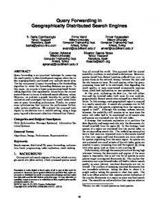
Buffalo Fig. 6b shows a similar cantilever-type specimen at nees@buffalo that was used to simulate the restoring forces corresponding to the Buffalo column substructure. The Buffalo reduced scale substructure had an initial stiffness of 0.32 kN/mm, yield displacement of 8 mm and a displacement capacity of 25 mm. The displacement and forces were also scaled to match the initial stiffness of the numerical full-scale column. Testing Procedure An incremental and modular testing procedure was employed to test operation of all the computer and control systems utilized in the test. Each remote site initially ran a local simulation of all the sites to ensure their software environment was properly configured to run the NTCP server and Simulation Coordinator. This local simulation was repeated with the local experiment enabled as a substructure with the simulation to test the NEESGrid interface to the control system. Then, the network connectivity and performance were verified by running a distributed test with all sites simulating a numerical substructure. A final end-to-end test was performed to ensure the integrated system performed to specification. After verifying all components, the actual hybrid simulation with experimental substructures was carried out. EVALUATION OF RESULTS The results from the Fast-MOST carried out on September 9, 2004 are presented below. During this particular run, the master numerical simulation including the simulation coordinator was located at Buffalo. There were two physical substructures: one at Berkeley and the other at Buffalo. Lehigh participated in this experiment as a remote numerical substructure, while the column substructures for Boulder and UIUC were simulated local to the master simulation in Buffalo. Simulation Results The computed displacement response of the bridge model subjected to the selected ground acceleration record is presented in Fig. 7. The figure shows the computed displacement at the five degrees of freedom that connect to the remote substructures. These displacement histories can also be interpreted as the command displacements generated for the five column substructures. Due to the axial rigidity of the bridge deck, the horizontal deformations of all the bridge columns along the longitudinal direction of the bridge are approximately the same. The small difference is due to axial deformations of the bridge deck. Fig. 8 presents the force deformation behavior of the two experimental column substructures during the Fast-MOST simulation. Note that the non-linear behavior demonstrated by the substructures from Berkeley and Buffalo are due to the actual measured behavior of the physical specimens. The hysteresis curves are mainly the result of yielding of the experimental substructures, although they can also include stiction and other sources of actuator displacement control errors. This measured restoring force was considered in the numerical simulation of the bridge model. The remaining three column substructures were simulated numerically. Step Timing and Network Delays The Fast-MOST simulation lasted 1074 seconds (0.3 hours) for 1500 numerical integration steps. Fig. 9 presents detailed information on the time duration per step. On average, the total step time duration was approximately 0.66 seconds. As shown in Fig. 9a, there were four steps with substantial delays of approximately 23 seconds and one with 3 seconds. These excessive delays were observed often during other trial runs with a similar frequency of occurrence. The source of these delays is likely in the network communication, resulting from the loss of data packets that need to be resent after a timeout. In total, these network delays increased to total test time by 90 seconds. More importantly, these long delays had a significant impact on the experimental substructure behavior. Fig. 9 shows the measured force-displacement data of the Berkeley experimental substructure between steps 1050 and 1100, which contains the third delayed step. The drop in force as the displacement passes the 0 mm
Displacement (mm)
100 50 0 Ŧ50 Ŧ100
0
5
10
15
Time (s)
Fig. 7. Computed displacement response of bride model and command signal for servo-hydraulic actuators
455
4000
4000
ubuf
Restoring force (kN)
Restoring force (kN)
ucal
2000 0 Ŧ2000 Ŧ4000
Ŧ50
2000 0 Ŧ2000 Ŧ4000
0 50 Displacement (mm)
Ŧ50
0 50 Displacement (mm)
a. Berkeley substructure response b. Buffalo substructure response Fig. 8 Experimentally measured force-displacement response of remote bridge column substructures 800
20
600
No. of steps
Total step time (s)
25
15 10
200
5 0
400
0
500 1000 Step number
0
1500
0
1 2 Total step time (s)
3
a. step duration b. histogram Fig. 9. Total step duration of 1500 steps during distributed test and corresponding histogram of data mark is caused by force relaxation during the actuator hold. Based on this observation, it is important to minimize the occurrence of delays and achieve a continuous load trajectory on the experimental substructures. Recovery from Network Failure During the four steps with delays of over 20 seconds, the Simulation Coordinator timed-out and re-issued the command for the current step, which resulted in the simulation continuing, as opposed to ending prematurely. This feature compensates for the unreliable nature of the internet and increases the reliability of the distributed system and its ability to complete the simulation. During these periods of delay, the test was on hold with no movement of the actuators, until network communications could be reestablished with all remote sites In other trial simulations, a more serious problem was encountered that required one remote site to restart their simulation in the middle of the experiment. To overcome this limitation, the simulation coordinator was configured to replay the experiment and bring the restarted site up to the current step by replaying the command for each step only to the failed site. Once the simulation coordinator reached the step in which the problem occurred, the simulation resumed normally with all the remote sites until successfully completed the experiment. This approach did not require the complete simulation to restart from the beginning. CONCLUSIONS A distributed control strategy was implemented into NEESGrid to support relatively fast and continuous hybrid simulation testing methods with geographically distributed substructures. The controller consists of a Restoring force (kN)
1000
500
0
Ŧ500 Ŧ100
Fig. 10.
Ŧ50 0 50 Displacement (mm)
100
Effects of time delays on yielded experimental substructure at Berkeley
456
multi-threaded simulation coordinator to communicate with all the remote sites in parallel and an event-driven controller to generate continuous load histories for the experimental substructures. These techniques were implemented in Fast-MOST, which showed considerable improvements compared to MOST. In particular, the duration of a 1500 step simulation was reduced from over five hours to under one-third of an hour. In additions to the time savings, the reliability of the results was improved by the minimization of force-relaxation and other strain-rate related errors in the experimental substructures. ACKNOWLEDGMENTS This work was supported in part by the NEES Program of the National Science Foundation under award number CMS-0086621 and CMS-0086611. Their support is gratefully acknowledged. Any opinions, findings, and conclusions or recommendations expressed in this material are those of the authors and do not necessarily reflect those of the National Science Foundation. The authors worked closely with the NEES System Integration team (Bill Spencer, Sridhar, Ghallapalli, and Laura Pearlman), University of Colorado at Boulder (Benson Shing and Eric Stauffer), Lehigh University (Jim Ricles and Peter Bryant) University of Illinois at Urbana Champaign (Narutoshi Nakata, Juan Carrion), University of California at Berkeley (Andreas Shellenberg, Tony Yang), and University at Buffalo (Xiaoyun Shao, Scot Weinreber ). REFERENCES Campbell, S. and Stojadinovic, B. (1998). “A system for simultaneous pseudodynamic testing of multiple substructures.” Proc., Sixth U.S. National Conf. on Earthquake Eng. Harel. D. (1987). “Statecharts: A visual formalism for complex systems.” Science of Computer Programming, 8, 231-274. Internet2 (2005) “About Abilene”, Abilene Backbone Network, http://abilene.internet2.edu/about Magonette, G. (2001). “Development and application of large-scale continuous pseudo-dynamic testing techniques.” Phil. Trans. R. Soc. Lond., 359, 1771-1799. Mahin S.A., Shing, P.B., Thewalt, C.R. and Hanson, R.D. (1989). “Pseudodynamic test method - Current status and future direction.” J. Struct. Eng., 115(8), 2113-2128. Mosqueda, G. (2003). “Continuous hybrid simulation with geographically distributed substructures.” Ph.D. Dissertation, Dept. of Civil an Environmental Eng., Univ. of California at Berkeley. Nakashima M., Kaminosono, T., Ishida, I. and Ando, K. (1990). “Integration techniques for substructure pseudo dynamic test. , Proc., Fourth U.S. National Conf. on Earthquake Eng. Nakashima M., Kato, M. and Takaoka, E. (1992). “Development of real-time pseudo dynamic testing.” Earthquake Eng. Struct. Dyn., 21(1):79-92. Nakashima M. and Masaoka, N. (1999). “Real-time on-line test for MDOF systems.” Earthquake Eng. Struct. Dyn., 28(4), 393-420. Nakashima, M. (2001). “Development, potential, and limitations of real-time online (pseudo-dynamic) testing.” Phil. Trans. R. Soc. Lond., 359, 1851-1867. Pearlman, L., D’Arcy, M., Johnson, E., Kesselman, C. and Plaszczak, P. (2003). “NEESgrid Teleoperation Control Protocol.” Technical Rep. NEESgrid-2003-07, NEESgrid. Pearlman, L., D’Arcy, M., Plaszczak, P. and Kesselman, C. (2004). “The NTCP Control Plugin” Technical Rep. NEESgrid-2004-26, NEESgrid. Spencer et al. (2004A). “The MOST experiment: earthquake engineering on the grid.” Technical Report NEESgrid-2004-26, NEESgrid. Spencer et al. (2004B). “NEESGRID: A distributed collaboratory for advanced earthquake engineering experiment and simulation.” Proc.s, Thirteenth World Conf. on Earthquake Eng., Paper No. 1674. Takanashi, K., Udagawa,K., Seki, M., Okada, T. and Tanaka, H. (1975). “Non-linear earthquake response analysis of structures by a computer-actuator on-line system (details of the system).” Trans. of the Architectural Institute of Japan, 229, 77-83. Takanashi, K. and Nakashima, M. (1987). “Japanese activities on on-line testing.” J. Eng. Mech., 113(7), 1014-1032. Tseng, W.S. and Penzien, J. (1973). “Analytical investigation of the seismic response of long multiple span highway bridges.” Rep. UCB/EERC-73/12. Earthquake Eng. Res. Center, Univ. of California, Berkeley. Tsai, K.-C., Yeh, C.-C., Yang, Y.-S. Wang, K.-J., Wang, S.-J. and Chen, P.-C. (2003). “Seismic Hazard Mitigation: Internet-based hybrid testing framework and examples.” International Colloquium on Natural Hazard Mitigation: Methods and Applications. Watanabe, E., Kitada, T., Kunitomo, S. and Nagata, K. (2001). “Parallel pseudo-dynamic seismic loading test on elevated bridge system through the Internet.” Eight East Asia-Pacific Conf. on Struct. Eng. and Const.