2004 IEEE 11th Digital Signal Processing Workshop. & IEEE Signal Processing Education Workshop. FAST IMAGE PROCESSING APPLICATION ...
2004 IEEE 11th Digital Signal Processing Workshop &
IEEE Signal Processing Education Workshop
FAST IMAGE PROCESSING APPLICATION DEVELOPMENT SCHEME FOR THE DSK C6711 USING MATLAB AND SIMULINK
Mario 1. Chacon M, Ivan Valenzuela 0. DSP& Vision Lab., Chihuahua Institute of Technology, Mexico ABSTRACT
This paper presents a methodology to incorporate cutting edge technologies, Matlab/Simulink, Code Composer Study and DSK. The purpose of this methodology is to provide the instructors and students in DSP related courses an efficient method to develop and test DSP applications. The methodology involves the current and very important professional vision used in many companies, design-simulation-implementation. Therefore, the methodology will also incorporate an added profit to the formation of our students. Another important benefit of this method is that it avoids low level hardware work that can be tedious and time consuming. This benefit will improve the learning process because the students can concentrate on important aspects of the concepts teaching in the course and not on implementation issues. The two applications presented in this paper prove the feasibility of this methodology.
1. INTRODUCTION
Digital signal processing, DSP, has proved to be an area of high impact in different areas of our real word. Therefore, a course or a series of courses have been incorporated into the electrical engineering curriculum at bachelor and graduate levels in most educational institutions. Theses courses include mainly theoretical aspects, concepts, and some practical exercises. Some of the possible challeng es faced for the instructors of these courses are, how to use new technologies to help the students to understand the concepts and how to teach these new technologies so they can apply them later in the laboratory. A new challenge that should be considered is how to incorporate edge DSP technolo gies so that students besides understanding DSP concept. and be able to apply them in laboratory environments, can manage edge DSP technologies so they can succeed in their future jobs. Some efforts have been done to deal with these cases [1 ][2J. However, due to the continuous development of new DSP technologies, it is also required new contributions to the integration of these technologies into the courses. This kind of contribution is the purpose of the work reported in this paper. The paper presents a scheme
0-7803-8434-2/04/$20.0002004 IEEE
to develop image processing applications for the DSK C671l using Matiab/Simulink, Code Composer Studio, CCS, cutting edge technologies, in an easy, understandable, and fast form. The application of this scheme in our laboratory has shown to be efficient even in complex applications, like image analysis including Gabor filters and artificial neural networks.
2. PRINCIPAL TECHNOLOGIES OF THE DEVELOPMENT SCHEME
The principal components of our scheme are, DSK TMS320C6711, MatIab/Simulink, and Code Composer Studio, CCS. The next section describes the main characteristics of these technologies. 2.1 DSK TMS320C6711
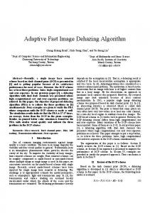
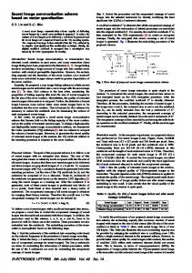
The DSK TMS320C6711 is a development board from Texas Instruments, Tl that includes the TMS320C6711 digital signal processor, DSP, plus an ADC/DAC. The board is connected to a PC host to development applications. The started kit is limited in memory and sampling speed 8k, but it can be improved through daughter boards to process even video. The kit can also improve its communication performance by using a ITAG communication emulator. Fig.!. shows the principal elements of the board. The DSK is the target hardware where the application is executed and tested in real time.
Fig. I
79
TMS320C6711 board.
Une In
l.ine
C6?'11 DSK
ADC
DAC
ADC
1
DSKC6711
�
Ou1
ce711 DSK
:!
�I
DAC
C0711 DSK '-ED LED
AeS:'lilt
i�
C0711 DSK DIP Switch
i
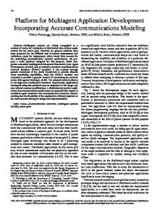
Fig. 2 Component interconnection.
I
Switch
:
L
,.=��= MC- C�_-�'"·�
,.•,,�
i
��
" ··''''·.-·-=''''·_�=·h==''''
-._,�j
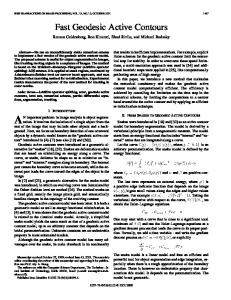
Fig.3 Simulink DSK block resources. 2.2
MatlabfSimulink
2.3 Code Composer Studio
Matlab is a high performance scientific environment [3]. Matlab has been used in our laboratory and in many other institutions [4][5] as an excellent tool to teach DSP concepts. The Matlab Link for CCS tool is used to establish communication and control between Matlab and CCS or Matlab and the DSK. This tool can open, compile and load a project into the CCS. With this tool we can also run or stop a program loaded into the DSK. Data transmission between Matlab and the DSK is performed through Real-Time Data Exchange,
RTDX, channels .
The CCS is used as an interface between Simulink and the DSK to test new algorithms in the DSK. The CCS is a development environment for the Texas Instrument DSP family. The CCS is used to build the project from the model generated by Simulink and for real time debugging. The projects generated by the CCS need to be modified sometimes
in
order
parameters in the
to
DSK. Fig.
adjust
some
configuration
5 shows the main window of
the CCS running an application.
Fig.2 illustrates this relationship.
language code through the Real Time Workshop, RTW. Real-Time Workshop is an extension of capabilities found
in Simulink and MATLAB
to enable rapid prototyping of
I
real-time software applications on a variety of systems [3]. The model also uses the Embedded Target for Texas Instruments C6000 DSPs to enable the communication
CCN liMn Ho
I.
Clert
JTI/) IrIertI:e
-
R1DX Has.
I
Urer
RTDnr¢UWj
I
� T&'g!I rqicm
tJ
DSK. In this work Simulink is used to generate models
in the DSK.
Ojlil
Simulink also provide us with a set of blocks, libraries
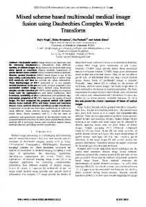
FigA PC host DSK communication.
called, Embedded Target for Texas Instruments C6000 DSPs,
CldoC,.�"
UIrrfy ---rr-
channels between the personal computer, the host, and the that can be loaded and tested
Trgo:l
H(I!J
Simulink is another Matlab tool able to generate C
ETT!. The ETTI blocks simplify the design task
3. GENERAL DEVELOPMENT SCHEME
since they represent DSK resources like the ADC, DA,
Leds, etc. These blocks can be used directly in the construction
of
an
application
in
the
Simulink
environment. Fig.3 presents some of these blocks. Another blocks included
in Simulink that is part of the
ETTI is RTDX Instrumentation. This block gives us
support to send and receive data to/from the DSK. FigA illustrates the link between the PC host and the
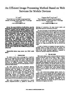
The general development scheme is shown in Fig.6. The scheme
includes
the
three
main
technologies,
Matlab/Simulink, CCS, and the DSK. The arrows indicate the communication among theses modules. The process starts with a model, algorithm, in Simulink. The Target Language Compiler from the Real -Time Workshop is
employed to generate the C code.
DSK using
This C code is
integrated into a CCS project with the Matlab Link for
the RTDX block.
CCS. ccs compiles, links, and loads the project into the
DSK.
80
At
this
time
Real-Time
Workshop
stops
its
Fig. 6 General scheme
we incorporate new resources to the DSK. For exam�[e . if we add the Audio Daughter card to the DSI.(, Slmuhnk does not provide a model for this resource.
Fig. 5 CCS environment. operation, and the algorithm is ready to be tested in the DSK. Information can be sent, or received between Matlab through the RTDX channels. Fig.7 Simulation parameters modified to discrete steps.
3.1 Simulink Configuration Since the DSK is a digital board, it works with fixed
3.3 RTDX Channels
discrete steps. Therefore it is necessary to change some simulation parameters in the Solver option. The Solver
The amount of data that it is possible to transmit to the
option is modified as shown in Fig. 7. Another form to make this change is by means of the function
DSK using the parallel port of the host without a
dspstarup
included in MatIab. The Real-time Workshop also needs
order
to be changed as illustrated in Fig.8.
to
increase
the
transmission
speed
it
is
recommended to include a JTAG emulator.
3.2 DSK Model Design Considerations
3. DEVELOPMENT OF APPLICATIONS
It is important to be aware that not all the blocks included
ITAG
emulator is 64K. The transmission speed is also low. In
In this section we describe the development of two
with Simulink can be used to generate code for
applications for image processing using the scheme
the DSK. The document Creating Your Simulink Model
described in this paper. The first one is the negative of
for Targeting provides information about this issue.
Another situation about model representation is when
81
open(rx, 'ichanl', 'w') ;%Open a WR channel open (rx, 'ochanl', 'r'),%Open a RD channel ee.rtdx.enable:%Enable RTDX cc.rtdx.isenabled;%Confirm RTDX enable pause(4);% wait enable(rx, 'ichanl');%Enable WR channel ee.rtdx.isenabled('ichanl');%Enable? if cc.rtdx.iswritable('ichanl');%WR? disp('writing to target ... '%Read indata
=
imread('C:\Doeuments and
Settings\ivano3\Mis documentos ... imagenes\pc.jpg');
Fig. 8 Select target Tl_C6000. an
Image
tic;
writemsg(rx, 'ichanl',
\Mis
%send image
uint8(indata) ,60)
toe; imshow(indata);
image and the second corresponds to an edge
detector.
end pause(3);%Wait for processing
The definition of the negative of an image in the range
ce.rtdx.isenabled('ochanl');
[O,L -1] is
enable (rx, 'oehanl');%Enable RD
s=L-l-r
(1)
ee.rtdx.isenabled('ochanl');%Enable? pause (5) ;
The Simulink model is shown in Fig.9.
num_of_msgs
=
msgeount(rx, 'oehanl')
if cc.rtdx.isreadable('ochanl');%RD? disp('reading from DSK... ' ) tic:
%Rd result
Qutdata
=
'uinta', [60
readmsg(rx, 'oehanl',
60),l,So);toc;
end pause(3); figure,imshow(outdata) ;%Show result flush(rx, 'ochanl', 'all') ;%Erase data disable(rx, 'ALL') ;%Disable channels close(rx, 'all');%Close channels
Fig. 9 Negative of an image Simulink model.
elear cc;%clear register ee
The next step is to build the project in CCS by using the
Fig 10 illustrates and example of this image processing
keys "ctrl+b". Once the project has been generated in
application.
CCS, open the file that corresponds to the project located in the folder
"Input/Output" and
DSP/BIOS config. Now open
select "RTDX Real-Time Data
Exchange Settings". Select "Properties" and change the value of "RTDX Buffer Size
(MAUs)"
from 1032 to
4096. Then save the project in CCS and compile and generate the file that will be loaded in the DSK. Now,
Fig. 10 a) original, b) negative.
load and run the program using File-Load. Fi nally send an image from Matlab using the following program. cc
=
ccsdsp;rx
=
A more complex application is described next. In this
ee.rtdx;
case
configure(rx,8192,4);%Configure 4 RTDX
an
edge detector based
on the
Laplacian
developed. One definition of the Laplacian is
82
is
V
2
f(x,y)
=
[- f(X + l,y -1)
-
f(x + l,y)
- f(x + l,y + 1) - fex -l,y -1) - f(x - 1, Y + 8f(x,y)
+
1)
-
f(x, Y -1)
-
-
4.
f(x -1,y) (2)
f(x, y + 1]
RESULTS AND CONCLUSIONS
We have presented in this paper a methodology to incorporate cutting edge technologies like Matlab/Simulink, CCS, and DSK. The purpose of this methodology is to provide the instructors and students in DSP related courses an efficient method to develop and test DSP applications. The paper described and illustrated the most important point to consider during the application of this methodology. The methodology presented involves the current and very important professional paradigm used in many companies, design simulation-implementation. Therefore, the methodology will also incorporate an added profit to the formation of our students. Another important benefit of this method is that it avoids low level hardware work that can be tedious and time consuming. This benefit will improve the learning process because the students can concentrate on important aspects of the concepts teaching in the course and not on implementation issues. Some restrictions and problems found in the incorporation of the technologies aforesaid were documented and solved when possible. Finally we can say that the applications presented in this paper have proved the feasibility of this methodology.
·
The Laplacian function is implemented with the S Function Builder that is employed to incorporate the C code for the Laplacian. Assuming that in our C code the input image is imin and the output image imout, these variables are declared in the S-Function Builder as shown in Fig 11. The C code is incorporated in the S-Function Builder and the block name is assigned. At this point we can compile the new function. The process generates several files, the file with extension tic has the information required for Simulink so we can use the new block with the DSK. The last step is to substitute the block S Function Builder for the block S-Function so it can be used by the RTW. The edge detector model is shown in Fig.l2. The result of this process is illustrated in Fig.13 .
5. ACKNOWLEDGEMENT
The authors greatly appreciate the support from CONACYT under grant PFPN-03-29-05 to develop this research.
6. REFERENCES [J]D. Orofino, "Rapid Prototyping of a Surveillance Video
Compression System," Matlab Digest, vol. 11, no. 5, Sep.
Fig. 11 Variable definitions in the S-Function Builder.
2003. [2]W. Gan, Y. Chong, W. Gong and W. Tan, "Rapid Prototyping for Teaching Real-Time Digital Signal Processing", IEEE Transactions on Education, vol. 43, no. 1, Feb. 2000.
[3]The MathWorks, Inc., Natick, MA, MATLAB: The
Language of Technical Computing, 2002.
[4]C. H. G. Wright, T. B. Welch and W. J. Gomes, "Teaching DSP Concepts Using Matlab and the TMS320C3J DSK", Proceedings of the IEEE
Fig. 12 Simulink edge detector model.
International Conference on Acoustics, Speech and Signal Processing, Mar. 1999.
[5]W. S. Gao, "Teaching and Learning the Hows and
Whys of Real-Time Digital Signal Processing", IEEE
Transactions on Education,
vol. 45, no. 4, Nov. 2002.
[6]R. C. Gonzalez, R. E. Woods, "Digital Image Prentice Hall, 2nd. Ed., 2002.
Fig. 13 Results of the Laplacian. a) Original, b) edges.
Processing",
83