92
CSEE JOURNAL OF POWER AND ENERGY SYSTEMS, VOL. 1, NO. 4, DECEMBER 2015
Application of Morphological Max-Lifting Scheme for Identification of Induction Motor Stator Inter-turn Short Circuit Y. Zhang, T. Y. Ji, Member IEEE, M. S. Li, Member IEEE, and Q. H. Wu, Fellow IEEE
Abstract—The harmonic components of stator winding current in induction motor will change under the condition of stator inter-turn short circuit. According to these characteristics, in this paper, a novel technique based on morphological maxlifting scheme is proposed for identification of induction motor stator inter-turn short circuit. A max-lifting scheme is applied to process stator winding currents to extract these characteristics. An indicator, r, is computed to identify the short circuit. The transient model of induction motor is employed to simulate oneturn to six-turn stator inter-turn short circuits in an induction motor. Extensive simulation work has been conducted under normal conditions, abnormal conditions (voltage imbalance and varying load), stator inter-turn short circuit conditions, and conditions of any combinations of the above. The results have shown that the scheme proposed in this paper has a high identification rate for induction motor stator inter-turn short circuit. Index Terms—Identification, induction motor, inter-turn short circuit, mathematical morphology, max-lifting scheme, varying load, voltage imbalance.
I. I NTRODUCTION
I
NDUCTION motors are widely used in many industrial applications thanks to their robustness, wide-ranging usability as well as low maintenance cost [1]. However, unscheduled component downtime of induction motors may cause significant financial loss. A general study conducted by IEEE [2] on the reliability of motors indicates that stator winding breakdowns account for nearly 37% of the failures of induction motor. Inter-turn short circuit, if undetected in early stage, may lead to major failures [3]. Therefore, there is a great need to detect the high-profile fault at the earliest stage [4]. The impact of inter-turn short circuit can be minimized with the help of accurate, effective and fast detection and diagnosis of any transient disturbances caused by stator interturn short circuit [5]. Intensive researches have been conducted to develop and implement reliable techniques for inter-turn short circuit diagnosis in induction motor. Modern approaches mainly involve extracting information from stator winding current [6], electromagnetic torque [7] or instantaneous input Manuscript received June 25, 2015; revised October 19, 2015; accepted October 20, 2015. Date of publication December 30, 2015; date of current version December 10, 2015. This work was supported by the Fundamental Research Funds for the Central Universities (2015ZZ019), and Guangdong Innovative Research Team Program (No. 201001N0104744201). Y. Zhang, T. Y. Ji (corresponding author), M. S. Li and Q. H. Wu are with the School of Electric Power Engineering, South China University of Technology, Guangzhou 510641, China (e-mail:
[email protected]). Digital Object Identifier 10.17775/CSEEJPES.2015.00052
power [8]. The majority of the developed diagnosis techniques are based on the negative-sequence components of stator winding current or electromagnetic torque. A number of fault diagnosis techniques have been used for induction motor stator inter-turn short circuit identification, such as short time Fourier transform (STFT), fast Fourier transform (FFT), bi-spectrum, high resolution spectral analysis, expert systems, fuzzy inference systems, neural networks, support vector machines, genetic algorithm and adaptive neutral fuzzy inference systems [9]–[13]. The research work mentioned above has adopted many advanced techniques to identify faults of induction motor, however, none of them has considered the influence of voltage imbalance on the induction motor. Moreover, some methods apply motor starting currents for the detection of inter-turn short circuit, as it is rarely polluted by noise; however, in practice motor starting currents are not always available to the diagnostic devices [14]. Wavelet functions, traditionally taking the Fourier transform as a construction tool, are defined as the dyadic translates and dilates of one particular mother wavelet function. This kind of wavelet is referred to as the first generation wavelet. Wavelet transform (WT) is excellent in extracting harmonic faulty components from source signals [15]. During the last decade, due to the advances in wavelet theory and the optimization of its different modes (continuous wavelet transform (CWT), discrete wavelet transform (DWT), wavelet packets, etc.), new wavelet-based diagnosis methods that are focused on the analysis of the start-up current have been proposed. Some recent examples regarding the application of WT to diagnosis can be found in [15]–[21]. To avoid obtaining wavelets by translating and dilating of one particular mother wavelet function but still enjoy the useful properties of the first generation wavelet, the second generation wavelet was introduced in [22]. The lifting scheme or simply lifting is a simple but powerful tool for constructing the second generation wavelet [23]. As a popular lifting scheme, the max-lifting scheme can preserve local maximum values of signals being processed with high calculation speed [24]. On the other hand, mathematical morphology (MM), as a nonlinear analysis method in time domain, has the advantages of high calculation speed and excellent de-noising performance [23]. To engage the advantages of the max-lifting scheme and MM, in this paper, a morphological max-lifting scheme is proposed for the identification of stator inter-turn short circuit under various conditions.
93
ZHANG et al.: APPLICATION OF MORPHOLOGICAL MAX-LIFTING SCHEME FOR IDENTIFICATION OF INDUCTION MOTOR STATOR INTER-TURN SHORT CIRCUIT
[µ]abcr
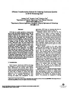
II. BACKGROUND K NOWLEDGE A. Transient Model of Stator Inter-turn-Faulted Induction Motor An illustration of an induction motor with a stator interturn short circuit fault on phase A is shown in Fig. 1 [25]. A short circuit of turns in the stator winding effectively introduces an extra winding in the motor winding structure. The rotor circuit is shown by a three-phase balanced winding. For the development of a simplified transient model, the basic assumptions are as follows: 1) The stator and rotor windings are balanced and sinusoidally distributed in healthy condition; 2) the machine has uniform air gap, the space harmonics due to stator and rotor slots are neglected, and there is no eccentricity in the machine air gap; and 3) there is no magnetic circuit saturation in the machine.
=
[µar µbr µcr ]>
=
[L]> sr [i]abcs + [L]rr [i]abcr .
The quantities in brackets indicate matrices of vectors. The notations of v, i, R, µ, L, Nf and Ns indicate the voltage, current, resistance, flux linkage, inductance, the number of faulted turns of phase A, and the total the number of turns of phase A, respectively. Subscripts s, r, and f denote quantities related to the stator, the rotor, and the fault circuit, respectively. Symbol [ ]> represents the transpose of the matrix. The inductance matrices of (1) are given by [L]ss = Lls diag{1 − λ λ 0 0} + Lms G (1 − µ)cosθr (1 − µ)cosE (1 − µ)cosF µcosθr µcosE µcosF [L]sr = Lms cosF cosθr cosE cosE cosF cosθr Llr + Lms −Lms /2 −Lms /2 [L]rr = −Lms /2 Llr + Lms −Lms /2 −Lms /2 −Lms /2 Llr + Lms where
(1 − µ)2 µ(1 − µ) G= −(1 − µ)/2 −(1 − µ)/2
µ(1 − µ) −(1 − µ)/2 µ2 −µ/2 −µ/2 1 −µ/2 −1/2
−(1 − µ)/2 −µ/2 −1/2 1
E = θr + 2π/3
Fig. 1. Electrical representation of induction motor with SIT fault [25].
F = θr − 2π/3. The fault is assumed to be present on one phase as a few turns shorted. The number of faulted turns is Nf out of the total number of turns Ns of the phase winding. The ratio of Nf to Ns is indicated by β in Fig. 1, which is the fault severity. The resistance of faulted turns is βRs . The leakage inductance of the faulted turns is assumed to be directly proportional to the square of the number of faulted turns [25]. 1) Motor Equations in ABC Phase Variables: The stator and rotor equations for a symmetrical induction machine with inter-turn short circuit faults can be expressed as [26]: d([µ]abcs ) dt d([µ]abcr ) 0 = [R]r [i]abcr + dt
[v]abcs = [R]s [i]abcs +
where [v]abcs = [vas1 vas2 vbs vcs ]> [i]abcs = [ias (ias − if ) ibs ics ]> [i]abcr = [iar ibr icr ]> [R]s
= Rs diag{1 − λ λ 0 0} = Rs diag{1 − Nf /Ns Nf /Ns 0 0}
(1) (2)
For the shorted turns (as2 ), the voltage and the flux linkage equations are vas2 = λRs (ias − if ) + p(µas2 ) µas2 = −λ[A1 ]> [i]s − λ[A2 ]> [i]r − λ(Lls + λLms )if
=
[µas1 µas2 µbs µcs ]>
=
[L]ss [i]abcs + [L]sr [i]abcr
(4)
where [A1 ] = [−(Lls + Lms ) Lms /2 Lms /2]> [A2 ] = −Lms [cosθr cosE cosF ]> . 2) Motor Equations in DQ0 Variables: The following matrix [K] is used to transform abc phase variables of stator and rotor into stationary reference frame dq0 variables. cos θ cos(θ − 2π ) cos(θ − 2π ) 3 3 2 sin(θ − 2π [K] = sin θ sin(θ − 2π 3 ) 3 ) 3 1 1 1 2
2
2
where θ is the instantaneous angular position of the dq0 frame [25]. Fig. 2 shows the graphical representation of this transformation. The dynamic equations of induction motor in dq0 variables are 1) voltage equations of stator:
[R]r = Rr diag{1 1 1} [µ]abcs
(3)
d 2 λqs − β[R]s if dt 3 d = Rs ids + λqs dt
vqs = Rs iqs +
(5)
vds
(6)
94
CSEE JOURNAL OF POWER AND ENERGY SYSTEMS, VOL. 1, NO. 4, DECEMBER 2015
B. Induction Motor Stator Inter-Turn Short Circuit Faulty Frequency Components
Fig. 2. Graphical representation of transformation of abc phase variables into arbitrary rotating reference frame dq0 variables.
d 1 λ0s − βRs if ; dt 3
(7)
0 = Rr iqr +
d λqr − ωr λdr dt
(8)
0 = Rr idr +
d λdr + ωr λqr dt
(9)
d λ0r dt
(10)
v0s = Rs i0s + 2) voltage equations of rotor:
0 = Rr i0r +
r where ωr = dθ dt . The flux linkage equations of induction motor in dq0 variables are 1) flux linkage equations of stator:
According to the space vector analysis, a three-phase symmetrical stator winding fed from a three-phase symmetrical supply with fundamental frequency f1 will produce a resultant forward rotating magnetic field at the synchronous frequency f1 in the air-gap [14]. When the magnetic field is applied to the rotor that rotates at frequency fr = (1 − s)f1 (s is slip), a current of slip frequency (i.e., f2 = sf1 ) will be induced in the rotor cage. A magnetic field, rotating at the slip frequency with respect to the rotating rotor and with the same number of poles as the stator magnetic field, will be produced by the rotor current. With symmetrical rotor conductors, only a forward rotating magnetic field exists in the air-gap. Any asymmetry of stator winding impedances caused by stator inter-turn short circuit will cause faulty rotating magnetic field. A range of papers have been published on the detection of induction motor stator inter-turn short circuit by analyzing rotating magnetic field existing in the air-gap. Previous studies have proved that the following equation gives the faulty frequency components in the rotating magnetic field [27]: n (20) fst = f1 ( (1 − s) ± k) p where n = 0, 1, 2, 3, . . ., k = 0, 1, 3, 5, . . . and f1 is the supply frequency. When these faulty frequency components act upon the stator winding, currents at the same frequency with the faulty frequency components in the rotating magnetic field will be induced in the stator winding.
2 λqs = Ls [i]qs + Lm [i]qr − βLs if 3
(11)
λds = Ls [i]ds + Lm [i]dr
(12)
C. MM and the Lifting Scheme
1 λ0s = − βLs if ; 3
(13)
1) Dilation and Erosion: Let f denote a signal and g denote a structuring element (SE), and the length of g be considerably shorter than that of f . Dilation and erosion are defined as [12]:
2 λqr = Lr iqr + Lm iqs − βLm if 3
(14)
f ⊕ g(x) = max{f (x + t) + g(t)|x + t ∈ D(f ), t ∈ D(g)} t (21) and
λdr = Lr idr + Lm ids
(15)
2) flux linkage equations of rotor:
f g(x) = min{f (x+t)−g(t)|x+t ∈ D(f ), t ∈ D(g)} (22) where
t
3 Ls = Lss + Lm 2
(16)
3 Lr = Lrr + Lm 2
(17)
where Lss is the sum of the stator’s self- and mutual inductances, Lrr is the sum of the rotor’s self- and mutual inductances, and Lsr is the mutual inductances of stator and rotor phase windings. The voltage equations for the faulted turns can be expressed as follows: vas2 = Rf if = βRs (iqs + i0s − if ) +
d λas dt 2
(18)
2 λas2 = βLls (iqs + i0s − if ) + βLm (iqs + iqr − βif ). (19) 3
respectively, where D(f ) and D(g) are the definition domains of f and g, respectively. 2) Opening and Closing: Opening is an operator that performs dilation on a signal eroded by the same SE. The definition of opening is given as [28]: f ◦ g = (f g) ⊕ g
(23)
where ◦ denotes the opening operator. Opening can recover most structures lost by erosion, except for those completely erased. Closing, on the other hand, can be defined by the duality of opening as f • g = (f ⊕ g) g (24) where • represents the closing operator.
95
ZHANG et al.: APPLICATION OF MORPHOLOGICAL MAX-LIFTING SCHEME FOR IDENTIFICATION OF INDUCTION MOTOR STATOR INTER-TURN SHORT CIRCUIT
3) The Lifting Scheme: A very general and useful technique for constructing new wavelet decompositions from existing ones has been recently proposed by Sweldens [29] and is known as the lifting scheme. A typical case of the lifting scheme consists of three stages: split, prediction, and update. 1) Split stage. Let x represent a one-dimensional discrete signal. x can be split into two parts, the approximation signal part x1 and the detail signal part y1 [11]. The most simple case is the one that splits x into even signal part xe (n) = x(2n) and odd signal part xo (n) = x(2n + 1). 2) Prediction stage. The detail signal y1 is predicted using information contained in the approximation signal x1 and is replaced by the prediction error y10
= y1 − P (x1 )
(25)
4) Morphological Filter: From (23)∼(26), it can be found that the opening operation can inhibit the positive peak noise and the closing operation can eliminate the negative low noise in the signal [30]. In order to utilize the advantages of opening and closing operations at the same time, three filtering algorithms are constructed as - Alternative filter: (f )oc(g1 , g2 ) = f ◦ g1 • g2
(33)
(f )co(g1 , g2 ) = f • cg1 ◦ g2
(34)
- Hybrid filter: (f )hf(g) =
f ◦g+f •g 2
(35)
- Alternative hybrid filter: where P represents the prediction operator. The prediction error y10 is defined as the new detail signal. The same information of the source signal x is preserved in the new detail signal since the detail signal y1 can be recovered by noting that y1 = y10 + P (x1 ).
(26)
Actually, the prediction procedure is equivalent to applying a high pass filter to the source signal x [28]. 3) Update stage. The approximation signal x1 is updated using the information contained in the new detail signal y10 : x01 = x1 + U (y10 )
(27)
where U represents the update operator. x01 is defined as the new approximation signal. The same information of the source signal x is preserved in the new approximation signal since the approximation signal x1 can be recovered by noting that x1 = x01 − U (y10 ).
(28)
Like WT, the aforementioned three stages are carried out on x1 recursively [23]. If the prediction and update operators are given by P (x1 )(n) = x1 (n) ∨ x1 (n + 1)
(29)
U (y1 )(n) = −(0 ∨ y1 (n − 1) ∨ y1 (n))
(30)
and
respectively, then y10 (n) = y1 (n) − (x1 (n) ∨ x1 (n + 1)) x01 (n)
= x1 (n) + (0 ∨
y10 (n
− 1) ∨
y10 (n)).
(31) (32)
The lifting scheme described above is the so-called maxlifting scheme. In the above max-lifting scheme, as a prediction for y1 (n) we choose the maximum of its two neighbors in x1 , i.e., x1 (n) and x1 (n + 1). The update stage is chosen in such a way that local maxima of the input signal x1 are mapped to the new approximation signal x01 [28].
(f )oc(g1 , g2 ) + (f )co(g1 , g2 ) (36) 2 where g1 and g2 are two different SEs, oc and co represent the open-closing and close-opening operations, respectively, hf represents hybrid filter operation, and ah represents alternative hybrid filter operation. (f )ah(g1 , g2 ) =
III. T HE P ROPOSED S CHEME The following cases are considered in the simulation studies: 1) normal situation; 2) abnormal situation; 3) stator phase A inter-turn short circuit situation. In this paper, normal situation means that no inter-turn faults exist in induction motor and three-phase voltages of this motor are symmetrical. The rated voltage, current and power of the induction motor simulated in this paper are 380 V, 7 A and 3.7 kW, respectively. The abnormal situation, including voltage imbalance and varying load situations, means that no inter-turn faults exist in induction motor and the three-phase voltages are asymmetry with negative sequence voltages, which are caused by stator voltage imbalance or load asymmetry of the induction motor. Voltage imbalance in a three-phase system is defined as the ratio of the magnitude of the negative sequence voltage to the magnitude of the positive sequence voltage, expressed as a percentage [31]. Typically, the voltage imbalance of a threephase service is less than 3% [31]. Mathematically, the voltage imbalance is defined as |V2 | Vi = × 100% (37) |V1 | where V2 is magnitude of the negative sequence voltage and V1 is magnitude of the positive sequence voltage. To express the severity of the stator inter-turn short circuit, in this paper, the short circuit turn ratio is defined as t1 × 100% (38) SCTR = t where t1 is the number of the shorted turns in phase A and t is the total number of turns of the simulated motor in phase A.
96
CSEE JOURNAL OF POWER AND ENERGY SYSTEMS, VOL. 1, NO. 4, DECEMBER 2015
The source signal x is split into two data series: xe (n) (even signal part of x) and xo (n) (odd signal part of x). The new detail signal d is obtained from d(n) = xo (n) − P (xe )(n)
(39)
where the prediction operator P is defined as
where A=
P (xe )(n) = max{A + B}
(40)
( N40 − i) × ((xe )oc(g1 , g2 ))(n)
(41)
B=
N0 4
i × ((xe )co(g1 , g2 ))(n) N0 4
where Ti = 0.8895 sin( 4iπ N0 ) (i = 1, 2, 3, . . ., m, and m = b N40 c), is selected as the SE used to deal with the signal shown in Fig. 3(a), the max-lifting scheme can detect and locate the state transitions accurately wherever these state transitions occur, as shown in Fig. 3(b). After detecting and locating state transitions, two-cycle stator winding currents under smooth load conditions are sampled as source signals, as shown in Fig. 4.
(42)
where i = 1, 2, 3, . . . , b N40 c, with bxc returning the largest integer smaller than or equal to x and N0 being the number of samples of a fundamental cycle. The proposed scheme is presented as follows. Step 1: Detect and locate the state transitions of the simulated induction motor using max-lifting scheme and sample two-cycle stator winding currents under smooth load conditions as source signals. Fig. 3(a) presents the current of a condition where the state of the simulated induction motor changes firstly from the normal situation to an abnormal situation (Vi = 1%) at n = 280, then from the abnormal situation to a stator interturn short circuit situation (SCTR = 1.5%) at n = 528, and finally back to normal situation at n = 840. For these three situations, the loads of the induction motor are the rated load, and the voltages of phase B and phase C are the rated voltage. Voltages of phase A of the normal situation and the abnormal situation are the rated voltage, and voltage of phase A of the stator inter-turn short circuit situation is smaller than the rated voltage, which is the cause of voltage imbalance.
Fig. 3. Detection of fluctuation of load. (a) Current. (b) Absolute value of the new detail signal, |d(n)|.
To eliminate the undesired influence of state transitions on the detection of inter-turn short circuit, the max-lifting scheme is adopted to detect these state transitions. When a sinusoidal signal, g1 = g2 = g = [0 T1 T2 . . . Tm−1 Tm Tm−1 . . . T2 T1 0] (43)
Fig. 4. Source signals when s = 0.015. (a) Normal situation. (b) An abnormal situation (Vi = 1%). (c) A stator inter-turn short circuit situation (SCTR = 1.5%).
Step 2: Extract faulty frequency components from source signals. In this paper, considering the range of s (0.01 ≤ s ≤ 0.05) in the rated operation situation [32], faulty frequency −2sf1 (p = 2, n = 4, k = 2) varies from 1 Hz to 5 Hz. Negative value means the faulty frequency component rotates in the opposite direction with respect to the rotating magnetic field. A current at frequency 2sf1 will be induced in the stator winding when the faulty frequency component is applied to the stator winding. To extract the faulty frequency component, the two SEs are defined as g1 = [0 T1 T2 . . . Tm−1 Tm ]
(44)
g2 = [Tm Tm−1 . . . T2 T1 0]
(45)
2iπ respectively, where Ti = xp sin( 5N ), with xp being the 0 amplitude of the fundamental frequency component of x and m being a positive integer. 200 cases of signals were used for training to select the optimal value of m and the parameter is set at m = N60 . In this step, the proposed max-lifting scheme is adopted to extract faulty frequency components from source signals. Fig. 5 presents the curves of d(n) of the signals shown in Fig. 4 when s = 0.015. To analyze the low frequency faulty components of inter-turn short circuit, FFT is applied to deal with d(n). The low frequency spectrum of the signals shown in Fig. 5 is depicted in Fig. 6. Step 3: Calculate the values of the indicator, r, which is defined in the next section. In this step, the values of the indicator, r, defined in the next section are calculated. These values will be used to construct the criterion which is proposed later.
ZHANG et al.: APPLICATION OF MORPHOLOGICAL MAX-LIFTING SCHEME FOR IDENTIFICATION OF INDUCTION MOTOR STATOR INTER-TURN SHORT CIRCUIT
97
except that in Figs. 7 and 8, the value of s is 0.020 and 0.025, respectively.
Fig. 5. The plots of d(n) when s = 0.015. (a) Normal condition. (b) An abnormal condition (Vi = 1%). (c) A stator inter-turn short circuit condition (SCTR = 1.5%). Fig. 7. Low frequency spectrum of d(n) when s = 0.020. (a) Normal condition. (b) An abnormal condition (Vi = 1%). (c) A stator inter-turn short circuit condition (SCTR = 1.5%).
Fig. 6. Low frequency spectrum of d(n) when s = 0.015. (a) Normal condition. (b) An abnormal condition (Vi = 1%). (c) A stator inter-turn short circuit condition (SCTR = 1.5%).
Step 4: Construct the criterion used for the identification of stator inter-turn short circuit. Based on the values of r calculated in the previous step, a practical criterion used for the identification of stator interturn short circuit is proposed and massive tests have been conducted to validate the accuracy of the criterion. IV. S IMULATION S TUDIES AND D ISCUSSION The curves of low frequency spectrum distributions of d(n) under normal condition, an abnormal condition and a stator inter-turn short circuit condition when s = 0.020 and s = 0.025 are shown in Figs. 7 and 8, respectively. The parameters of the currents shown in these figures are the same as in Fig. 5,
Fig. 8. Low frequency spectrum of d(n) when s = 0.025. (a) Normal condition. (b) An abnormal condition (Vi = 1%). (c) A stator inter-turn short circuit condition (SCTR = 1.5%).
After extracting the low frequency components of the source signals, the characteristics of these components are analyzed for the detection of stator inter-turn short circuit. Let Fn (f ), Fa (f ) and Fs (f ) be the values of the low frequency spectrum of d(n) at frequency f under normal, abnormal and stator inter-turn short circuit conditions, respectively. In Fig. 7 (c), when an inter-turn short circuit occurs in induction motor stator when s = 0.020, low frequency spectrum of d(n) takes its maximum value, Fs−max (f ), at 2sf1 , which in this case is 4 Hz. As shown in Fig. 7, Fn (2sf1 ) and Fa (2sf1 ) are both remarkably smaller than Fs−max (f ).
98
CSEE JOURNAL OF POWER AND ENERGY SYSTEMS, VOL. 1, NO. 4, DECEMBER 2015
0
V. L ABORATORY E XPERIMENT A laboratory experiment platform, shown in Fig. 13, was established to test the proposed scheme. This platform is composed of four parts: a highly efficient programmable AC source, Chroma 61511, used to provide symmetric three phase voltages with low distortion sine waves; four types of typical
2
3
4
5
6
6 5 4 3 2 1 0
(46)
0
50
100
150
Conditions
Fig. 9. The values of r when Vi = 0%.
8 0
1
2
3
4
5
6
7 6 Indicator
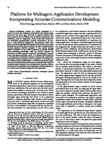
where Fr (f ) represents the real time monitoring value of low frequency spectrum of d(n) at frequency f . Fig. 10 shows the values of r under various conditions when Vi = 1%. In this figure, condition 50 of the horizontal axis represents the condition that the load of rotor phase A is 50% of the rated load, and 0, 1, 2, 3, 4, 5 and 6 in the legend represent no, single-turn, two-turn, three-turn, four-turn, five-turn and six-turn inter-turn short circuit fault conditions, respectively. In Fig. 10, all of the values of r under normal and abnormal conditions are less than 1.5, and all of the values of r under stator inter-turn short circuit conditions are greater than 1.5. Therefore, in this paper, r > 1.5 is selected as criterion used to identify various inter-turn short circuits. To verify the validity of the proposed criterion, a great number of tests were carried out by varying the value of Vi . Figs. 9, 11 and 12 give the values of r under varies conditions when Vi = 0%, Vi = 2% and Vi = 3%, respectively. As shown in these figures, only one out of 54 values of r under normal and abnormal conditions is greater than 1.5; only one out of 324 values of r under various stator inter-turn short circuit conditions is less than 1.5. Therefore, when r > 1.5 is selected as the criterion for the identification of induction motor stator inter-turn short circuits, 99.68% inter-turn short circuits can be identified accurately. A great number of tests have been conducted by varying the parameters and the models of the induction motor, and the test results have verified that the above criterion has a high identification rate of induction motor stator inter-turn short circuit. The voltage signals and power signals have been used as input signals to examine the feasibility of the proposed method, and the test results have proved that, the reliability of the scheme is not affected whether voltage signals or power signals are considered as the input signals. However, when power signals are considered as the input signals, the computational burden of the proposed scheme will be twice as high as that of the case when only voltage signals or current signals are in the input list.
1
7
5 4 3 2 1 0
0
50
100
150
Conditions
Fig. 10. The values of r when Vi = 1%. 8 0
1
2
3
4
5
6
7 6 Indicator
Fr (2sf1 ) r= Fn (2sf1 )
8
Indicator
A great number of tests have been conducted by changing the load, the stator voltage and the value of s of induction motor, and similar phenomena have been observed. Test results have demonstrated that low frequency spectrum of d(n) takes its maximum value, Fs−max (f ), under stator inter-turn short circuit conditions at 2sf1 , and Fn (2sf1 ) and Fa (2sf1 ) are both remarkably smaller than Fs−max (f ). Based on the above test results and analysis, an indicator, r, is computed to identify stator inter-turn short circuit:
5 4 3 2 1 0
0
50
100
150
Conditions
Fig. 11. The values of r when Vi = 2%.
loads: a three-phase motor, a single-phase motor, a singlephase transformer and several slide rheostats; an oscilloscope used to display and record real-time voltage signals; a DELL PC with a 2.3 GHz Intel(R) Core(TM) i3-2350M CPU and 4.00 GB of RAM used to process the signals using MATLAB. The above four loads were connected or disconnected to generate induction motor stator inter-turn short circuits. Fig. 14 shows the values of r under real time operating conditions. In this figure, all of the values of r under normal and abnormal conditions are less than 1.5, and all of the values of r under stator inter-turn short circuit conditions are greater than 1.5. Therefore, the criterion of r > 1.5 has a high identification rate for induction motor stator inter-turn short circuit.
ZHANG et al.: APPLICATION OF MORPHOLOGICAL MAX-LIFTING SCHEME FOR IDENTIFICATION OF INDUCTION MOTOR STATOR INTER-TURN SHORT CIRCUIT
8 0
1
2
3
4
5
99
R EFERENCES
6
7
Indicator
6 5 4 3 2 1 0 0
50
100
150
Conditions
Fig. 12. The values of r when Vi = 3%.
Fig. 13. Laboratory experiment platform. 8 0
1
2
3
4
5
6
7
Indicator
6 5 4 3 2 1 0 0
50
100
150
Conditions
Fig. 14. The values of r under real time operating conditions.
VI. C ONCLUSION A novel scheme based on morphological max-lifting scheme has been proposed for the identification of stator inter-turn short circuit under voltage imbalance and varying load conditions. A transient model of stator inter-turn-faulted induction motor has been constructed, and stator voltage signals under normal, abnormal and stator inter-turn short circuit conditions have been simulated using this model. Moreover, a laboratory experiment platform has been set up to further verify the proposed scheme under real operation conditions. Extensive simulation and experimental studies have been carried out, and the results have shown the superiority of the proposed scheme.
[1] V. Kuptsov, A. Sarvarov, and M. Petushkov, “A new approach to analysis of induction motors with rotor faults during startup based on the finite element method,” Progress in Electromagnetics Research B, vol. 45, no. 45, pp. 269–290, Oct 2012. [2] R. Bell, D. McWilliams, P. O’Donnell, C. Singh, and S. Wells, “Report of large motor reliability survey of industrial and commercial installations, part I and II,” IEEE Transactions on Industry Applications, vol. 21, no. 4, pp. 865–872, Jul 1985. [3] A. Stavrou, H. Sedding, and J. Penman, “Current monitoring for detecting inter-turn short circuits in induction motors,” IEEE Transactions on Energy Conversions, vol. 16, no. 1, pp. 32–37, Mar 2001. [4] J. Seshadrinath, B. Singh, and B. Panigrahi, “Single-turn fault detection in induction machine using complex-wavelet-based method,” IEEE Transactions on Industry Applications, vol. 48, no. 6, pp. 1846–1854, Nov 2012. [5] S. Saleh, M. Khan, and M. Rahman, “Application of a wavelet-based MRA for diagnosing disturbances in a three-phase induction motor,” in the Fifth IEEE International Symposium on Diagnostics for Electric Machines, Power Electronics and Drives, Vienna, Austria, 7-9 Sep 2005, pp. 1–6. [6] K. Kyusung and A. Parlos, “Induction motor fault diagnosis based on neuropredictors and wavelet signal processing,” IEEE/ASME Transactions on Mechatronics, vol. 7, no. 2, pp. 201–219, Jun 2002. [7] T. Liu and J. Huang, “A novel method for induction motors stator interturn short circuit fault diagnosis by wavelet packet analysis,” in the Eighth International Conference on Electrical Machines and Systems, Nanjing, China, 27-29 Sep 2005, pp. 2254–2258. [8] M. Drif and A. Cardoso, “Stator fault diagnostics in squirrel cage threephase induction motor drives using the instantaneous active and reactive power signature analyses,” IEEE Transactions on Industrial Informatics, vol. 10, no. 2, pp. 1348–1360, May 2014. [9] M. Sahraoui, A. Ghoggal, S. Guedidi, and S. Zouzou, “Detection of inter-turn short-circuit in induction motors using Park-Hilbert method,” International Journal of System Assurance Engineering and Management, vol. 5, no. 3, pp. 337–351, Jul 2014. [10] A. Jawadekar, S. Paraskar, S. Jadhav, and G. Dhole, “Artificial neural network-based induction motor fault classifier using continuous wavelet transform,” Systems Science & Control Engineering, vol. 2, no. 1, pp. 684–690, Nov 2014. [11] Y. Amara and G. Barakat, “Modeling and diagnostic of stator faults in induction machines using permeance network method,” in Progress in Electromagnetics Research Symposium, Morocco, 20-23 Mar 2011, pp. 1550–1559. [12] P. V. J. Rodriguez and A. Arkkio, “Detection of stator winding fault in induction motor using fuzzy logic,” Applied Soft Computing, vol. 8, no. 2, pp. 1112–1120, Sep 2007. [13] R. Abiyev and O. Kaynak, “Fuzzy wavelet neural networks for identification and control of dynamic plants-a novel structure and a comparative study,” IEEE Transactions on Industrial Electronics, vol. 55, no. 8, pp. 3133–3140, Aug 2008. [14] B. Lu and M. Paghda, “Induction motor rotor fault diagnosis using wavelet analysis of one-cycle average power,” in the Twenty-Third Annual IEEE Applied Power Electronics Conference and Exposition, Austin, USA, 24-28 Feb 2008, pp. 1113–1118. [15] H. Douglas, P. Pillay, and A. Ziarani, “Broken rotor bar detection in induction machines with transient operating speeds,” IEEE Transactions on Energy Conversion, vol. 20, no. 1, pp. 135–141, Mar 2005. [16] T. Chow and S. Hai, “Induction machine fault diagnostic analysis with wavelet technique,” IEEE Transactions on Industrial Electronics, vol. 51, no. 3, pp. 558–565, Jun 2004. [17] A. Mohanty and C. Kar, “Fault detection in a multistage gearbox by demodulation of motor current waveform,” IEEE Transactions on Inductrial Electronics, vol. 53, no. 4, pp. 1285–1297, Jun 2006. [18] F. Briz, M. Degner, P. Garcia, and D. Bragado, “Broken rotor bar detection in line-fed induction machines using complex wavelet analysis of startup transients,” IEEE Transactions on Industry Application, vol. 44, no. 3, pp. 760–768, May 2008. [19] S. Rajagopalan, J. Aller, J. Restrepo, T. Habetler, and R. Harley, “Analytic-wavelet-ridge-based detection of dynamic eccentricity in brushless direct current (BLDC) motors functioning under dynamic operating conditions,” IEEE Transactions on Industrial Electronics, vol. 54, no. 3, pp. 1410–1419, Jun 2007. [20] Z. Ye, B. Wu, and A. Sadeghian, “Current signature analysis of induction motor mechanical faults by wavelet packet decomposition,” IEEE
100
[21]
[22] [23] [24] [25] [26] [27] [28] [29]
[30] [31] [32]
CSEE JOURNAL OF POWER AND ENERGY SYSTEMS, VOL. 1, NO. 4, DECEMBER 2015
Transactions on Industrial Electronics, vol. 50, no. 6, pp. 1217–1228, Dec 2003. J. Cusido, L. Romeral, J. Ortega, J. Rosero, and A. Garcia Espinosa, “Fault detection in induction machines using power spectral density in wavelet decomposition,” IEEE Transactions on Industrial Electronics, vol. 55, no. 2, pp. 633–643, Feb 2008. H. Heijmans and J. Goutsias, “Nonlinear multiresolution signal decomposition schemes. II. morphological wavelets,” IEEE Transactions on Image Processing, vol. 9, no. 11, pp. 1897–1913, Nov 2000. H. Douglas, P. Pillay, and A. Ziarani, “A new algorithm for transient motor current signature analysis using wavelets,” IEEE Transactions on Industry Applications, vol. 40, no. 5, pp. 1361–1368, Sep 2004. F. Trutt, J. Sottile, and J. Kohler, “Online condition monitoring of induction motors,” IEEE Transactions on Industry Applications, vol. 38, no. 6, pp. 1627–1632, Nov 2002. D. Patel and M. Chandorkar, “Modeling and analysis of stator interturn fault location effects on induction machines,” IEEE Transactions on Industrial Electronics, vol. 61, no. 9, pp. 4552–4564, Sep 2014. R. Tallam, T. Habetler, and R. Harley, “Transient model for induction machines with stator winding turn faults,” IEEE Transactions on Industry Applications, vol. 38, no. 3, pp. 632–637, May 2002. W. Thomson and M. Fenger, “Current signature analysis to detect induction motor faults,” IEEE Industry Applications Magazine, vol. 7, no. 4, pp. 26–34, Jul 2001. M. Arkan, D. Kostic-Perovic, and P. Unsworth, “Modelling and simulation of induction motors with inter-turn faults for diagnostics,” Electric Power Systems Research, vol. 75, no. 1, pp. 57–66, May 2005. M. Benbouzid, M. Vieira, and C. Theys, “Induction motors’ faults detection and localization using stator current advanced signal processing techniques,” IEEE Transactions on Power Electronics, vol. 14, no. 1, pp. 14–22, Jan 1999. Y. Zhang and Y. Qu, “Design of morphological filter based on family of straight lines structure element,” in Power Engineering and Automation Conference, Wuhan, China, 18-20 Sep 2012, pp. 1–4. “IEEE Recommended Practice for Monitoring Electric Power Quality,” IEEE Std 1159-2009 (Revision of IEEE Std 1159-1995), pp. c1–81, Jun 2009. Y. Q. Cao, L. M. Yan, M. D. Li, and W. Z. Yan, “Slip of induction motor with frequency speed control,” Journal of Southwest Jiaotong University, vol. 41, no. 1, pp. 37–41, Feb 2006.
Yin Zhang received the B.Eng. degree in Electrical Engineering and Automation from Qufu Normal University, in 2011. In 2015, he obtained his M.Sc. degree in Electric Power Engineering from South China University of Technology, Guangzhou, China. He is now a Teaching Assistant at School of Electrical and Information Engineering, Guangxi University of Science and Technology. His research area includes mathematical morphology and signal processing, and their application in power systems.
Tianyao Ji received a B.Eng. degree in Information Engineering in 2003, a B.A. degree in English in 2003 and a M.Sc. degree in Signal and Information Processing in 2006 from Xi’an Jiaotong University, Xi’an, China. In 2009, she obtained the Ph.D. degree in Electrical Engineering and Electronics from University of Liverpool, Liverpool, U.K. From 2010 to 2011, she worked as a research associate in University of Liverpool for two years. She is now an Associate Professor at School of Electric Power Engineering, South China University of Technology. Her research interests include mathematical morphology, signal and information processing, power system protection and evolutionary computation.
Mengshi Li received an M.Sc.(Eng) degree with distinction in Information and Intelligence Engineering from the Department of Electrical Engineering and Electronics, the University of Liverpool, U.K., in 2005. He received the PhD degree in Electrical Engineering from University of Liverpool, U.K., in 2010. He is currently a Lecturer in School of Electric Power, South China University of Technology. His research interests include computational intelligence and their applications in power systems.
Q. H. Wu (M’91, SM’97, F’11) obtained a Ph.D. degree in Electrical Engineering from The Queen’s University of Belfast, Belfast, U.K. in 1987, and subsequently worked as a Research Fellow. He joined the Department of Mathematical Sciences, Loughborough University, Loughborough, U.K. in 1991, as a Lecturer and subsequently as a Senior Lecturer. In 1995, he joined University of Liverpool, Liverpool, U.K. as the Chair of Electrical Engineering. Now he is with the School of Electric Power Engineering, South China University of Technology, Guangzhou, China, as a Distinguished Professor and the Director of Energy Research Institute of the University. Professor Wu has authored and coauthored more than 450 technical publications. He is a Fellow of IEEE, Fellow of IET, Chartered Engineer and Fellow of InstMC. His current research interests include smart grid, mathematical morphology, smart energy automation chips, evolutionary computation, power system control and operation.