Department of Computer Science and Institute for Advanced Computer Studies,. University of Maryland, College Park, MD 20742. (Dated: 31 December 2007). Abstract. The development of a fast multipole method accelerated iterative solution of the ...... The Boundary Element Method in Acoustics (Available online at.
Fast Multipole Accelerated Boundary Element Methods for the 3D Helmholtz Equation Nail A. Gumerov and Ramani Duraiswami Perceptual Interfaces and Reality Laboratory, Department of Computer Science and Institute for Advanced Computer Studies, University of Maryland, College Park, MD 20742 (Dated: 31 December 2007)
Abstract The development of a fast multipole method accelerated iterative solution of the boundary element equations for large problems involving hundreds of thousands elements for the Helmholtz equations in 3D is described. The BEM requires several approximate computations (numerical quadrature, approximations of the boundary shapes using elements) and the convergence criterion for iterative computation. When accelerated using the FMM, these different errors must all be chosen in a way that on the one hand excess work is not done and on the other that the error achieved by the overall computation is acceptable. Details of translation operators used, choices of representations, and boundary element integration consistent with these approximations are described. A novel preconditioner for accelerating convergence, using a low accuracy FMM accelerated solver as a right preconditioner is also desceibed. Results of the developed and tested solvers for boundary value problems for the Helmholtz equations using the solver are presented for the number of unknowns N � 106 and product of wavenumber k times domain size D, kD � 200 and show good performance close to theoretical expectations. PACS numbers: 43.20.Rz, 43.55.Ka Keywords: Fast Multipole Method, Boundary Element Method, Preconditioning, Low Frequency, High Frequency, Scattering
1
I.
INTRODUCTION
Boundary element methods (BEM) have long been considered as a very promising technique for the solution of many problems in computational acoustics governed by the Helmholtz equation. They can handle complex shapes, lead to problems in boundary variables alone, and lead to simpler meshes where the boundary alone must be discretized rather than the entire domain. Despite these advantages, one issue that has impeded their widespread adoption is that the integral equation techniques lead to linear systems with dense and possibly non-symmetric matrices. For a problem � � with N unknowns, direct solution requires O(N 3 ) solution cost, and storage of O N 2 elements
of these matrices. The computation of the individual matrix elements is also expensive requiring quadrature of nonsingular, weakly singular, or hypersingular functions. To reduce the singularity order and achieve symmetric matrices, many investigators employ Galerkin techniques, which lead � � to further O N 2 integral computations. Direct solution of the linear systems has an O(N 3 ) cost. Use of iterative methods does not reduce the memory or integral computation costs, but can reduce the cost to O(Niter N 2 ) operations, where Niter is the number of iterations required, and the O(N 2 ) per iteration cost arises from the dense matrix-vector product. In practice this is still quite large. An iteration strategy that minimizes Niter is also needed. Because of these reasons the BEM was not used for very large problems. The development of the fast multipole method (FMM) [15] and use of preconditioned Krylov iterative methods presents a promising approach to improving the scalability of integral equation methods. The FMM for potential problems allows the matrix vector product to be performed to a given precision � in O(N ) operations, and further does not require the computation or storage of all N 2 elements of the matrices, reducing the storage costs to O(N ) as well. Incorporating this fast matrix vector product in a quickly convergent iterative scheme allows the system of equations to be rapidly solved with O(Niter N ) cost. The FMM was initially developed for gravity or electrostatic potential problems. Later this method was intensively studied and extended to solution of many other problems, including those arising from the Helmholtz, Maxwell, biharmonic and elasticity equations. While the literature and previous work on the FMM is extensive, reasons of space do not permit us to provide a complete discussion of the literature. We refer the reader to the comprehensive review [21]. Numerical solution of the Helmholtz equation is somewhat complicated since the equation con-
2
tains a length scale parameter (the wavenumber) at which order the solution must be resolved. The FMM for the Helmholtz equations also exploits factorized representations of the Green’s function. However, for the Helmholtz equation the size of the representations, and the cost of translations are all related to the wavenumber, and this makes the assessment of costs more complicated, and the development of FMM accelerated BEM more involved. We discuss these issues further below. Despite several publications related to the FMM accelerated BEM for scattering [13, 14, 26—30] there are several issues which must be resolved. These include • Choice of translation scheme which is stable and efficient over a range of wavenumbers • Choice of appropriate preconditioned Krylov iteration method, and associated preconditioner • Ability to resolve problems caused at wavenumbers at which the corresponding interior problem has resonances via the Burton-Miller technique • Efficient implementations that achieve predicted scalings in CPU time and memory We discuss these issues further in the context of the contributions of this paper, and distinguish it from previous published work.
A.
Error and fast multipole accelerated boundary elements
Since the FMM achieves an approximate matrix vector product, we should emphasize that in practice this accuracy can be made close to machine precision. In any case an accuracy criterion is employed to stop the iterative process, and the accuracy of the FMM should be considered together with accuracy of the BEM technique. The latter is quite approximate in practice, since significant errors are introduced via surface approximation via discretization and less significant ones via approximate computation of the boundary integrals. In practice (see e.g., [3, 14, 26]) error tolerances are quite high (from a high of a few percent to at most 10−4 ). Since these errors all influence the final solution error, it does not make sense to perform any particular part of the calculation, with an exceedingly high precision. In fact all errors must be balanced so that the specified error is achieved.
3
B.
Resolving calculations at all wavenumbers
To be accurate, any calculation must resolve the smallest wavelengths of interest, and to satisfy the Nyquist criterion, the discretization must involve at least two points per wavelength. The restriction imposed by this requirement manifests itself at large enough frequencies, since at lower frequencies the accuracy of shape representation is more restrictive. So two basic regimes are usually recognized: the low-frequency regime and the high-frequency regime. These regimes can be characterized by some threshold value (kD)∗ of parameter kD, where k is the wavenumber and D is the computational domain size. For each of these regimes the complexity of the FMM is different [18]. The goal of the FMM is to reduce this per iteration cost, while preconditioning attempts to reduce the number of iterations.
1.
Low frequency regime
In this regime kD < (kD)∗ and the per iteration step cost of the FMM can be expressed as Cost per step = O (N ) × CT, where CT is the cost of translations, where CT and N do not depend on kD and can be determined based on the required accuracy of computations. The choice of the translation scheme affects CT, and so the asymptotic constant, as the overall complexity will be in any case O(Niter N ). For the low frequency regime the most efficient translation schemes are based on the RCR (rotation-coaxial translation-back rotation) decompositions [17, 18], which have O(p3 ) complexity, where p2 is the number of terms in the multipole expansion (p in this regime can be constant), and based on the low-frequency exponential forms [10, 16], which have the same complexity, but with a different asymptotic constant. The method based on sampling of the far field signature function [23] are not stable in this region due to exponential growth of terms in the multipole-to-local translation kernel.
2.
High frequency regime
In this regime kD > (kD)∗ and kD heavily affects the complexity of the FMM. In practice 5 to 10 points per wavelength are required. Since the wavenumber k is inversely proportional to wavelength, if a numerical method is a surface based method (such as the boundary element method), then 4
� � problem size N scales as O (kD)2 , while for complex, space-filling surfaces (e.g. problem with � � many scatterers distributed in a volume) N scales as O (kD)3 . Direct solution procedures require O((kD)4 ) memory and O((kD)6 ) operations for simple shapes and O((kD)6 ) memory and O((kD)9 ) � � operations for space-filling surfaces, while iterative solution can be achieved for O (kD)4 memory � � � � and O (kD)4 computation per iteration cost for simple shapes and O (kD)6 complexities for space-filling surfaces.
The high-frequency FMM is designed in this case to increase the size of wavefunction representation, O(p2 ), as levels go up in the hierarchical space subdivision, with p proportional to the size of the boxes at given level [18]. Because of this the complexity of the FMM is heavily affected by the complexity of a single translation. It is shown that O(p3 ) schemes in this case provide the over� � � � all complexity of the FMM O (kD)3 for simple shapes and O (kD)3 log(kD) for space-filling surfaces. The use of translation schemes of O(p4 ) and O(p5 ) complexities in this case provides the � � � � overall complexity of the FMM O (kD)4 and O (kD)5 for simple shapes and, in fact the use
of such schemes has no complexity advantage compared to the direct matrix-vector multiplication. Despite this some authors used such high complexity translation schemes for the BEM (e.g. [28]), which therefore limits practical use of their software to the low-frequency regime.
In a sense of reaching the best scaling algorithm in this regime translation methods based on sampling of the far-field signature function [23] are appropriate. Translation cost in this case scales as O(p2 ), while at least O(p2 log p) additional operations are needed for the spherical filtering necessary for numerical stabilization of the procedure. In this case the overall FMM complexity will � � � � be O (kD)2 logα (kD) (α � 1) for simple shapes and O (kD)3 for space-filling shapes. However, it is noteworthy, that function representations via samples of the far-field signature function are at
least twice as large as those for the multipole expansions. Also the multipole-to-local translation kernel should be sampled with double frequency compared to the translated function size, which increases the size of the transforms and complexity of filtering. These costs means that the value of p at which the asymptotically efficient algorithm performs better than the O(p3 ) algorithm can be high.
5
3.
Switch in function representations
The use of the FMM for the BEM even at high kD requires use of different translation schemes for fine and coarse levels of space subdivision. Indeed at the fine levels parameter ka, where a is a representative box size is small enough and translations efficient for low-frequency regime should be used, while for coarse levels this parameter is large and the high-frequency regime should be treated efficiently. So a combined scheme in which the spherical wave function representation can be converted to signature function sample representation can be applied. Such a switch was suggested and tested recently in [5]. In the present paper we also use a switch, while our scheme is different � � and does not require interpolation/anterpolation. We use O p3 spherical transform, while this can be replaced by methods of lower asymptotic complexity (such as based on FFT or 1D-FMM, [5, 18]) for larger problems, though in our experience the costs for the range of kD considered in this paper, are comparable. The spherical wavefunction based representation is convenient for differentiation, and this allows easier implementation of the Burton-Miller method, as the differential operators there can be easily expressed in terms of the expansion coefficients, as is shown further below.
C.
Iterative methods and preconditioning
The second issue with fast multipole acceleration is the choice of preconditioning strategy. Preconditioning for boundary element matrices is in general a lesser studied issue than for finite element and finite difference based discretization. From that theory, it is known that for high wave numbers preconditioning is difficult, and an area of active research. Many conventional pre-conditioning strategies rely on sparsity in the matrix, and applying them to these dense matrices requires computations that have a formal time or memory complexity of O(N 2 ), which negates the advantage of the FMM. One strategy that has been applied with the FMBEM is the construction of approximate inverses for each row based on a local neighborhood of the row . If K neighboring elements are considered, then constructing this matrix has a cost of O(N K 3 ) and there is a similar cost to applying the preconditioner at each step [13, 14]. However such local preconditioning strategies work well only well for low wavenumbers. Instead we consider the use of a low accuracy FMM itself as a preconditioner by using a flexible GMRES procedure [24]. This novel preconditioner appears to work well at all wavenumbers considered, and stays within the required cost. 6
II.
FORMULATION AND PRELIMINARIES A.
Boundary value problem
We consider numerical solution of the Helmholtz equation for the possibly complex valued potential φ ∇2 φ + k2 φ = 0,
(1)
with real wavenumber k inside or outside finite three dimensional domain V bounded by closed surface S, subject to mixed boundary conditions α (x) φ (x) + β (x) q (x) = γ (x) ,
q (x) =
∂φ (x) , ∂n
|α| + |β| = � 0,
x ∈S.
(2)
Here and below all normal derivatives are taken assuming that the normal to the surface is directed outward to V . For external problems we also assume that the field satisfies the Sommerfeld radiation condition � � �� ∂φ lim r − ikφ = 0, r→∞ ∂r
r = |x| .
(3)
This means that for scattering problems φ is treated as the scattered potential. Note then that there should be some constraints on surface functions α (x) , β (x), and γ (x), for existence and uniqueness of the solution (e.g. α (x) and β (x) cannot be simultaneously zero), and we rely on the typical physically meaningful conditions, which make the problem of determination of φ (x) well-posed. Particularly, if α and β are constant we have the Robin problem, which degenerates to the Dirichlet or Neumann problem, if β = 0 (sound-soft boundary) and α = 0 (sound-hard boundary), respectively. Variation of α and β along the surface happens e.g., when we consider problems with variable impedance. Also this covers the case when on some part of the boundary φ (x) is known, while on another part of the boundary its normal derivative is provided. In this case α (x) , β (x), and γ (x) are piecewise smooth.
B.
Boundary integral equations
The boundary element method uses a formulation in terms of boundary integral equations whose solution with the boundary conditions provides the values of φ (x) and q (x) on the boundary. 7
Knowledge of these quantities enables determination of φ (y) for any domain point y. This can be done, e.g. using Greens identity ±φ (y) = L [q] − M [φ] ,
y ∈S. /
(4)
Here the upper sign in the left hand side should be taken for the internal domain while the lower the lower sign is for the external domain (this convention is used everywhere below), and L and M denote the following boundary operators: ∂G (x, y) L [q] = q (x) G (x, y) dS(x), M [φ] = φ (x) dS(x), ∂n (x) S S
(5)
where G is the free-space Green’s function for the Helmholtz equation G (x, y) =
eikr , 4πr
r = |x − y| .
(6)
In principle, Green’s identity can be also used to provide necessary equations for determination of the boundary values of φ (x) and q (x), as in this case we have for smooth S 1 ± φ (y) = L [q] − M [φ] , 2
y ∈S.
(7)
The well-known deficiency of this formulation is related to possible degeneration of operators L � � and M − 12 at certain frequencies depending on S, which correspond to resonances of the internal problem for sound-soft and sound-hard boundaries [2, 4]. Even though the solution of the external
problem is unique for these frequencies, Eq. (7) is deficient in these cases, since it provides a nonunique solution. Moreover, despite the spurious values of resonance frequencies, for frequencies in the vicinity of the resonances the system becomes poorly conditioned numerically. On the other hand, when solving internal problems (e.g. in room acoustics), the non-uniqueness of the solution for the internal problem, seems to have physical meaning, as there, in fact, can be resonances. In any case, boundary integral equation (7) can be modified to avoid the artifact of degeneracy of boundary operators when solving the correctly posed problem (1)-(3). This can be done using different techniques, including direct and indirect formulations, introduction of some additional field points, etc. We use direct formulation based on the integral equation combining Green’s and Maue’s identities, which is the same trick as proposed by Burton and Miller (1971) for sound-hard boundaries. The latter identity is 1 ± q (y) = L� [q] − M � [φ] , 2
y ∈S,
(8) 8
where
∂G (x, y) L [q] = q (x) dS(x), ∂n (y) S �
∂ M [φ] = ∂n (y) �
S
φ (x)
∂G (x, y) dS(x). ∂n (x)
(9)
Multiplying Eq. (8) by some complex constant λ and summing with Eq. (7), we obtain � � � � 1 ± [φ (y) + λq(y)] = L + λL� [q] − M + λM � [φ] . 2
(10)
Burton & Miller [2] proved that it is sufficient to have Im (λ) �= 0 to guarantee uniqueness of the solution for the external problem.
C.
Combined equation
The system of equations (2) and (10) can be reduced to a single linear system for some vector of unknowns [ψ] A [ψ] = c,
(11)
which is convenient for computations. Boundary operator A, and functions ψ and c can be constructed as follows (this is equivalent to elimination of one of the unknowns ψ or q on the part of the boundary, based on the magnitude of coefficients α (x) and β (x)). Let σ (x) be a logical function so that 1, |α (x)| � |β (x)| σ (x) = , 0, |α (x)| > |β (x)|
(12)
Then we define
ψ = σφ + (1 − σ) q.
(13)
Furthermore, we introduce new variables � � � � β α u = σ − (1 − σ) ψ, u� = −σ + (1 − σ) ψ, α β γ γ b = − (1 − σ) , b� = −σ , α β
(14)
with the remark that in case α = 0 we have logical σ = 1 and (1 − σ) /α should be set to zero. The same relates to β = 0 where we have σ/β = 0. Also u and u� are proportional to a single unknown 9
ψ and can be found easily if ψ is specified. From these definitions and boundary conditions (2) we have φ = σφ + (1 − σ) φ = σφ + (1 − σ) q = σq + (1 − σ) q = σ
γ − βq = u − b, α
(15)
γ − αφ + (1 − σ) q = u� − b� . β
Substituting these expressions into Eq. (10) we obtain Eq. (11), where � � � � � � 1� A [ψ] = L+λL� u� − M+λM � [u] ∓ u + λu� 2 � �
� � � � � 1 c = L+λL� b� − M+λM � [b] ∓ b + λb� . 2
(16)
As soon as equation (11) is solved and ψ is found, we can determine u and u� from Eq. (14) and φ and q from Eq. (15).
D.
Discretization
Boundary discretization leads to approximation of boundary functions via finite vectors of their surface samples and integral operators via matrices acting on that vectors. For example, if the surface is discretized by a mesh with M panels (elements), Sl� , and N vertices, xj , and integrals over the boundary elements can be computed, we obtain M � � � (c) L [q] xl =
l� =1 Sl�
M � � � (c) q (x) G x, xl dS(x) ≈ Lll� ql� ,
� � (c) ql� = q xl� ,
Lll� =
Sl�
l = 1, ..., M,
(17)
l� =1
� � (c) G x, xl dS(x),
(c)
where xl� is the center of the l� th element, and for computations of matrix entries Lll� one can use well-known quadratures, including those for singular integrals [4, 20]. Similar formulae can be used for other operators. Note that to accurately capture the solution variation at the relevant length scales, the discretization should satisfy krmax � 1,
(18)
where rmax is the maximum size of the element. In practice, discretizations which provide several elements per wavelength are usually provide an accuracy consistent with the other errors of the BEM. 10
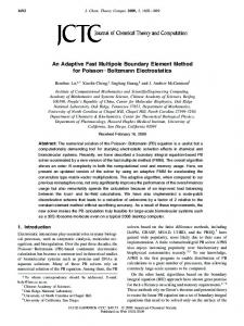
We have implemented and tested the above method of discretization with collocation at the panel centers. We also used another method while provides collocation at the vertices, which are located on the surface S, and sometimes more convenient as it leads to smaller systems. It can be shown that formally both have the same accuracy, despite the fact that vertex collocation has linear element functions. Formally, this is based on the following geometrical consideration. We note that in the case when a triangular surface mesh is available, each triangle of area Sl with vertices xl1 , xl2 , and xl3 is subdivided into six triangles Sl��� of equal areas by its medians (the fact which is easy to prove using elementary geometry), which intersect at the triangle center (c)
xl
= (xl1 + xl2 + xl3 ) /3. After that the smaller triangles having common vertex xj can be united
into a non-flat patch with center xj which area sj is 1/3 of the sum of the areas of original triangles which include vertex xj . This is schematically shown in Fig. 1. If not given, the normal to the surface at xj for smooth enough surfaces can be approximated by a sum of normals to those elements weighted by areas. So we have sj =
�
Sl�� =
Sl�� �xj
1 � Sl , 3 Sl �xj
nj =
1 � nl Sl . 3sj
(19)
Sl �xj
Discretization of surface operator with collocation at the vertices can be then written as
L [q] (xj ) = =
M �
l=1 Sl N �
q (x) G (x, xj ) dS(x) =
� l�� =1 Sl�� N �
q (x) G (x, xj ) dS(x) ≈
j � =1 sj �
Ljj � =
6M �
q (x) G (x, xj ) dS(x) =
sj �
q (x) G (x, xj ) dS(x)
(20)
Ljj � qj �
j=1
�
Sl�� �xj
G (x, xj ) dS(x),
qj = q (xj ) ,
j = 1, ..., N.
Sl��
In any case there exists a large literature and available subroutines for computation of the integrals over flat triangular elements including nearly singular, singular, weakly singular, and hypersingular cases [4]. Below we also propose a novel method for treatment of singular integrals. Discretization of the boundary operators reduces problem (11) to a system of linear equations which for small sized systems can be solved directly, while for larger problems iterative methods can be used to speed up computations.
11
E.
Iterative Methods
Different iterative methods can be tried to solve equation (11) with a non-symmetric dense matrix A. Any iterative method requires matrix-vector multiplication or computation of A [x], where [x] is some input vector. For large systems we use the FMM (Fast Multipole Method) to achieve reduction in the memory and operational complexity in the way described below. The method of our choice is fGMRES (Flexible Generalized Minimal Residual Method) [24], which has an advantage of use of approximate right preconditioner, which in its turn can be computed by executing of the internal iteration loop using unpreconditioned GMRES [25]. Different preconditioners can be tried as soon as they provide grouping of matrix eigenvalues about 1 or approximate the matrix inverse. Choice of the preconditioning method must be achieved for a cost that is O(N ) or smaller. Also in some cases we employed the FMM for system preconditioning.
III.
USE OF THE FAST MULTIPOLE METHOD
The basic idea of the use of the FMM for solution of the discretized boundary integral equation is based on decomposition of operator A: A = Asparse + Adense ,
(21)
where the sparse part of the matrix has only nonzero entries Alj corresponding to the vertices xl and xj , such that |xl − xj | < rc , where rc is some distance usually of the order of the distance between the vertices, which selection can be based on some estimates or error bounds, while the dense part has nonzero entries Alj for which |xl − xj | � rc . Storage and multiplication of the sparse matrix has memory and computational complexity O(N ) as soon as N × N matrices are considered, while the corresponding complexities for the dense part are both O(N 2 ), if direct methods are considered. The use of the FMM reduces the memory complexity to O(N ) and the computational complexity to o(N 2 ), which can be O(N), O(N logβ N ), β � 1, or O(N α ), α < 2, depending on the wavenumber, domain size, effective dimensionality of the boundary, and translation methods used [18]. The decomposition (21) is at the heart of the FMM, with summation of the near-field interactions performed directly, while for the far-field interactions multipole and local expansions are used. The acceleration achieved is via memory and time efficient computation of the matrix-vector products involving Adense . 12
A.
FMM strategy
The use of the FMM for solution of boundary integral equations brings a substantial shift in the computational strategy. In the traditional BEM, since the full system matrix should be computed to solve the resulting linear system either directly or iteratively. The memory needed to store this matrix is fixed and is not affected by the accuracy imposed on computation of the surface integrals. Even if one uses quadratures with relatively high number of abscissas and weights to compute integrals over the flat panels in a constant panel approximation the memory cost is the same, and the relative increase in the total cost is small, as that cost is dominated by the linear system solution. If one chooses, it is also possible to compute non-singular integrals very accurately in the FMM using expansions of Green’s function, such as ∞ � n � � � � � � � (c) (c) (c) (c) G x, xl = ik Rn−m x − xl� Snm xl −xl� ,
(22)
n=0 m=−n
where Rnm and Snm are the spherical basis functions for the Helmholtz equation, we obtain from Eq. (17) Lll� =
∞ � n �
n=0 m=−n
Cnm Snm
�
(c) (c) xl −xl�
�
,
Cnm
= ik
Sl�
� � (c) Rn−m x − xl� dS(x).
(23)
As the sum is truncated for maximum n = p − 1 then we have p2 complex expansion coefficients for each element. If this p is the same as the truncation number for the FMM, this requires substantial memory to store Mp2 complex values. All methods, based on high order quadratures, computations of the expansion coefficients or use of some analytical formulae with compositionally complex functions impose substantial limits on the use of the advantages of the FMM, which otherwise is capable to handle million size problems on usual desktop PCs. To reduce the memory consumption one should use schemes where the integrals are computed at the time of the matrix-vector product and only at the necessary accuracy. In the case of the use of higher order quadratures we face then with a well-known dilemma to compute integrals in the flat panel approximation with high number of nodes, or just increase the total number of nodes (discretization density) and use low order quadrature. In the case of use of the FMM with “on fly” integral computations the computational complexity will be almost the same for both of these ways, while the latter way seems preferable, as it allows the function vary from 13
point to point and employs better approximation for the boundary (as the vertices are located on the actual surface and variations of the normal are accounted better). Of course these variations in any case should be small enough, for the method to converge. We also note that based on our experience for the same problem (geometry and wavelength) the number of iterations to achieve convergence, after some N (once the system is resolved ) almost does not depend on N . Therefore, in the case of the use of the FMM we can try to use the following approximation, at least in the far-field, for the non-singular integrals (in case of vertex collocation): Llj = sj G (xj , xl ) , L�lj = sj
∂G (xj , xl ) , ∂nl
∂G (xj , xl ) , ∂nj ∂2G Mlj� = sj (xj , xl ) , ∂nl ∂nj
Mlj = sj
(24) l, j = 1, ..., N,
xl �= xj .
Collocation at the panel center uses the same formulae with respective values of areas, nodes and normals. For the treatment of the singular integrals (xl = xj ) we use a method described later. As we mentioned above we use these approximations for computations of the product involving the dense part of the matrix, or the far field. For near field computations these formulae could be used with a fine enough discretization for the non singular integrals, though one may prefer to use higher order quadrature. We performed several tests using for near field integral representation Gauss quadratures of varying order (in range 1-625 nodes per element) and found that approximation (24) used for near field provides fairly good results for good meshes (the element size and aspect ratios stay within some bounds), though some poor meshes provide not so good results, and we provide this choice as a switch in the code.
B.
FMM algorithm
The Helmholtz FMM algorithm which we employed for matrix vector products is described in [18, 19], with modifications that allows use of different translation schemes for low and high frequencies. Particulars of our algorithm are that we use level-dependent truncation number pl and rectangularly truncated translation operators for multipole-to-multipole and local-to-local translations, which are performed using rotation-coaxial translation-rotation (RCR) decomposition and result in O(p3 ) single translation complexity. The RCR-decomposition is also used for the multipole-to-local translations for levels with kal < ka∗ , where al is the radius of the smallest sphere surrounding a box on level l, and ka∗ is some critical value of the size parameter. For levels corresponding to 14
kal � ka∗ we convert the multipole expansions to samples of the signature function at a cost of O(p3 ), then employ diagonal forms of the translation operator O(p2 ), and in the downward pass at some appropriate level use conversion of the signature function to the local expansion of the required length at a cost of O(p3 ). This procedure automatically provides filtering. We also note that conversions from multipole and to local expansions are required only once per box, since consolidation of the translated functions is performed in terms of signature functions. This amortizes the O(p3 ) conversion cost and makes the scheme faster than the one based on the RCR-decomposition for the same accuracy. So our algorithm, in this part, is close to that described in [5]. The difference is that we do not need any interpolation/anterpolation procedures. Also for low-frequency translation we used RCR-decomposition for the multipole-to-local translation, which we found as efficient as the method based on conversion into exponential forms for moderate p. Particulars of our implementation include precomputation of all translation operators, particularly translation kernels, so during the run time of the procedure, which is performed many times for the iterative process only simple arithmetic operations (additions and multiplications) are executed. Below we briefly describe some details of the algorithm.
1.
Data structure
The present version of the FMM employs a traditional octree-based data structure, when the computational domain is enclosed into a cube of size D × D × D which is assigned to level 0 and further the space is subdivided by the octree to the level lmax . The algorithm works with cubes from level 2 to lmax . For generation of the data structure we use hierarchical box ordering based on the bit interleaving and precompute lists of neighbors and children, which are stored and used as needed. So the adaptivity of the FMM used is in skipping of “empty” boxes at all levels (such boxes simply do not enter the data structure). It is perhaps because of our use of these data structures that even on a modest PC the times we report for the FMM matrix vector product are superior to those of several authors.
2.
Level dependent truncation number
Each level is characterized by the size of the expansion domain, which is a sphere of radius al concentric with the box. Selection of the truncation number in the algorithm is automated based 15
on equation pl = p(kal , �, δ), where � is the prescribed accuracy of the FMM, and δ is the separation parameter (we used δ = 2 (see the justification in [18])). Detailed discussion and theoretical error bounds for such dependences can be found elsewhere (e.g. [9, 18]). Particularly, the following approximation combining low and high-frequency asymptotics for monopole expansions can be utilized [18]: 1 1 plow = ln � + 1, ln δ � 1 − δ−1 �3/2 � �1/4 p = p4low + p4high .
phigh
� � 1 1 2/3 = ka + (ka)1/3 , 3 ln 2 �
(25)
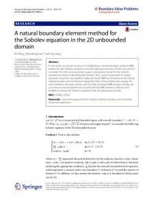
It is also shown in [18] that for the use of the rectangularly truncated translation operators the principal term of the error can be evaluated based on this dependence. The numerical experiments show that the theoretical bound frequently overestimates the actual errors, so some corrections can be also applied. In our automatic settings we computed plow and phigh and if it happened that p − phigh > p∗ (�), where p∗ is some number dictated by the overall accuracy requirements (for the errors acceptable for this paper constant p∗ = 5 was good enough for most cases tested; in fact, this function should be proportional to ln(1/�)) we used p = p0 + phigh , otherwise Eq. (25) was used. As mentioned above, in the algorithm we implemented an automatic switch from the RCRdecomposition to the diagonal forms of the translation operators based on criterion kal � ka∗ . Parameter ka∗ was based on the error bounds (25) and was selected for the level at which p−phigh � p∗∗ (we used p∗∗ = 2). This is dictated by the estimation of the threshold at which the magnitude of the smallest truncated term in the translation kernel (33) starts to grow exponentially (see [18]). Fig. 2 shows the dependences provided by Eq. (25). We note that FMM with very small accuracy like � = 10−2 can be used for efficient preconditioning. We also can remark that function representation via the multipole expansions and use of the matrix-based translations (such as RCR-decomposition) is not the only choice, and in [5, 10] a method based on diagonalization of the translation operators, different from [23] were developed. This method, however requires some complication in data structure (decomposition to the x, y, z-directional lists) and efficient for moderate to large truncation numbers. As we mentioned, the truncation numbers in the lowfrequency region can be reduced (plus the BEM itself has a limited accuracy due to flat panel discretization). In this case efficiency of the matrix-based methods, such as the RCR-decomposition is comparable, or even better. Indeed, function representations via the samples of the far field signature functions are at least two times larger, which results in larger memory consumption and 16
reduction of efficiency on operations on larger representing vectors.
3.
Multipole expansions
Expansions over the singular (radiating) spherical basis functions Snm (r) in the form (22)-(23) can be applied to represent the monopole source or respective integrals. In these formulae the singular and regular solutions of the Helmholtz equation are defined as Snm (r) = hn (kr)Ynm (θ, ϕ),
Rnm (r) = jn (kr)Ynm (θ, ϕ),
n = 0, 1, 2, ...;
m = −n, ..., n,
(26)
where in spherical coordinates r =r (sin θ cos ϕ, sin θ sin ϕ, cos θ) symbols hn (kr) and jn (kr) denote spherical Hankel (first kind) and Bessel functions, and Ynm (θ, ϕ) the spherical harmonics � 2n + 1 (n − |m|)! |m| P (cos θ)eimϕ , Ynm (θ, ϕ) = (−1)m 4π (n + |m|)! n n = 0, 1, 2, ...,
(27)
m = −n, ..., n,
|m|
and Pn (µ) are the associated Legendre functions consistent with that in [1], or Rodrigues’ formulae � �m/2 dm Pnm (µ) = (−1)m 1 − µ2 Pn (µ) , dµm �n 1 dn � 2 Pn (µ) = n µ − 1 , n � 0, n 2 n! dµ
n � 0,
m � 0,
(28)
where Pn (µ) are the Legendre polynomials.
In the boundary integral formulation also normal derivatives of Green’s function should be expanded (or integrals of these functions over the boundary elements). These expansions can be obtained from expansions of type (22)-(23) for the monopoles by applying appropriately truncated differential operators in the space of the expansion coefficients [18] , which are sparse matrices and so the cost of differentiation is O(p2 ). Indeed if {Cnm } are the expansion coefficients of some � � �nm are the expansion coefficients over the same basis of function F (r) over basis Snm (r), while C function n · ∇F (r) for unit normal n = (nx , ny , nz ), then
� � � −m m−1 �� m+1 −m−1 m+1 m−1 m−1 �nm = 1 (nx + iny ) bm C (29) n Cn−1 − bn+1 Cn+1 + (nx − iny ) bn Cn−1 − bn+1 Cn+1 2t � � m m m +nz am m = 0, ±1, ±2, ..., n = |m| , |m| + 1, ... n Cn+1 − an−1 Cn−1 , 17
m where am n and bn are the differentiation coefficients � (n + 1 + m)(n + 1 − m) −m am , for n � |m| , = n = an (2n + 1) (2n + 3)
(30)
m am for n < |m| , n = bn = 0, � (n − m − 1)(n − m) bm for 0 �m � n, n = (2n − 1) (2n + 1) � (n − m − 1)(n − m) bm for − n � m 30 which provided at least 6 elements per wavelength and increased the number of elements proportionally to (kD)2 (the maximum case plotted corresponds to kD = 173 where the mesh contains 135,002 vertices and 270,000 elements). The total CPU time required for solution of the problem is scaled approximately as O((kD)3 ) which is consistent with the theory if the number of iterations is constant. In fact, for the cases computed the number of iterations both in the inner and outer loops of the preconditioned fGMRES was growing with kD, however this growth was not very substantial (e.g. for the outer loop 8 iterations for kD = 10 , while 14 iterations for kD = 173 to converge to the value of the residual 10−4 ). The total number of iterations in the inner loop grow also, but substantially because of the growth of the number of iterations in the outer loop, while the average number of inner iterations per one outer iteration was varying in range (1-8) (in any case the inner loop was limited by maximum 10 iterations). The overall accuracy was controlled by comparison with the analytical solution (50) and in most cases the maximum absolute error (L∞ -norm) was in the range 1-2 % at kD > 3. In range 3 < kD < 30 the error increases a couple of times if we keep constant χ ≈ 0.94. We decreased this parameter to maintain the same error. For kD < 3, which we characterize as very low frequency regime, we used constant mesh with 866 vertices and 1728 elements. This mesh provided errors in range 10−4 −10−2 for all cases. Also for this range we used used λ = 0. This provided faster convergence, despite selection based on Eq. (53) with η = 0.03 also provided accurate results. In fact, at low frequencies the discretization can be reduced further to have consistent 1% accuracy, but since we tried to test the FMM, which works efficiently only for problem sizes N � 103 we fixed the discretization in this range. Another acceleration (several times) comes from precomputation and storage of the near-field integrals in the BEM (matrix Asparse , Eq. (21)). However, based on the RAM (we used 3.5 GB) this works only for N below 105 . So to show scaling we did not use such storage and recomputed the sparse matrix entries each time as the respective matrix-product was needed.
B.
More complex shapes
Many problems in acoustics require computations for substantially complex shapes, which includes bioacoustics, human hearing, sound propagation in dispersed media, engine acoustics, room acoustics, etc. We tested our algorithm by solving several problems like that and Fig. 8 provides an idea on the sizes and geometries we were working on. We note that modeling of complex shapes
28
requires surface discretizations which is determined not only by the wavelength based conditions χ � 2π, but also by the requirements that the topology and some shape features should be properly represented. Indeed even for solution of the Laplace equation (k = 0) the boundary element methods can use thousands and millions of elements just properly represent the geometry. Usually the same mesh is used for multifrequency analysis, in which case the number of elements is fixed and selected to satisfy criteria for the largest k required. In this case the number of elements per wavelength for small k can be large. Also, of course, discretization plays an important role in the accuracy of computations. So if some problem with complex geometry should be solved with high accuracy then the number of elements per wavelength can be again large enough. For the last geometry illustrated in Fig. 8 we conducted some study on the method performance and accuracy for the range of kD from 0.35 to 175 (ka = 0.01 − 5, where a is the largest axis of an ellipsoid). First, we should note that the surface of each ellipsoid was discretized with more than 1000 vertices and 2000 elements to provide an acceptable accuracy of the method even for low frequencies. Indeed, we checked that the convergence for the Neumann, Dirichlet, and Robin problems was very fast (just a few iterations) for small ka, where, as we discussed above the use of low-frequency FMM is important. For this problem both formulations, based on the Green’s identity and Burton-Miller equation are acceptable, while instead of scaled value (53) of the regularization parameter in the latter formulation, some small constant value is more appropriate at small ka (in fact at ka � 1 there is no any internal resonance modes, so Green’s identity works well). The convergence was not affected by the increase of the number of nodes, and, in principle, discretization with the number of elements of order 100 was in this sense acceptable. Nonetheless we should increase discretizations, since the accuracy of computations suffered from poor shape representation (as a test solution we used an analytical solution, when a source was placed inside one of the ellipsoids and surface values and normal derivatives were computed at each vertex location analytically). The quality of the mesh is also important (our mesh was obtained by simple mapping of a regular mesh on a cube surface to the ellipsoid surface). For larger discretizations as we used we were able achieve ~1% relative errors in strong norm (L∞ ) for the range of parameters we used. Fig. 9 shows an absolute relative error at each vertex � � � (BEM ) (an) � − φi � �φi � � �i = , i = 1, ..., Nvert , � (an) � φ � i � 29
(54)
(an)
(BEM)
where φi and φi are the analytical and BEM solutions, and the modulus of the � � � (an) � solution�φi �. The maximum error here was max (�i ) = 1.58%, which is usually acceptable for physics based problems and engineering computations.
VI.
CONCLUSION
We presented here a version of the FMM accelerated BEM, where a scalable FMM is used both for dense matrix-vector multiplication and preconditioning. The equations solved are based on the Burton-Miller formulation. The numerical results show scaling consistent with the theory, which far outperforms conventional BEM in terms of memory and computational speed. Realization of the FMM for efficient BEM requires different schemes for treatment of low and high frequency regions, and switching from multipole to signature function representation of solution of the Helmholtz equation is important for broadband BEM. The tests of the methods for simple and complex shapes show that it can be used for efficient solution of scattering and other acoustical problems encountered in practice for a wide range of frequencies.
VII.
ACKNOWLEDGEMENTS
This work was partially supported by a Maryland Technology Development Corporation grant to the authors.
[1] Abramowitz, M., and Stegun, I. A. (1964) Handbook of Mathematical Functions (National Bureau of Standards, Washington, D.C.). [2] Burton, A. J. and Miller, G. F. (1971). “The application of the integral equation methods to the numerical solution of some exterior boundary-value problems,” Proc. Roy. Soc. London, Series A, Math. Phys. Sci. 323, 201—210. [3] Chandrasekhar, B., and Rao, S. M. (2004). “Acoustic scattering from rigid bodies of arbitrary shape– double layer formulation,” J. Acoust. Soc. Am., 115,1926-1933. [4] Chen, L. H., and Zhou, J. (1992). Boundary Element Methods (Academic Press, New York). [5] Cheng, H., Crutchfield, W. Y., Gimbutas, Z. , Greengard, L. F. , Ethridge, J. F., Huang, J., Rokhlin, V., Yarvin, N., and Zhao, J. (2006). “A wideband fast multipole method for the Helmholtz equation in three dimensions,” J. Comput. Phys., 216, 300-325.
30
[6] Chew, W. C., Jin, J. M., Michelssen, E., and Song, J. (eds.) (2001). Fast and Efficient Algorithms in Computational Electromagnetics (Artech House, Boston). [7] Colton, D., and Kress, R. (1998). Inverse Acoustic and Electromagnetic Scattering Theory (SpringerVerlag, Berlin). [8] Darve, E. (2000). “The fast multipole method: numerical implementation, J. Comput. Phys., 160, 195—240. [9] Darve, E. (2000). “The fast multipole method (I): error analysis and asymptotic complexity,” SIAM J. Numer. Anal., 38, 98—128. [10] Darve, E., and Havé, P. (2004). “Efficient fast multipole method for low-frequency scattering,” J. Comput. Phys., 197(1), 341—363. [11] Driscoll, J. R., and Healy, D. M., Jr. (1994) “Computing Fourier transforms and convolutions on the 2-sphere,” Advances in Appl. Math., 15, 202-250. [12] Epton, M. A., and Dembart, B. (1995) “Multipole translation theory for the three-dimensional Laplace and Helmholtz equations,” SIAM J. Sci. Comput., 16, 865-897. [13] Fischer, M. (2004) The Fast Multipole Boundary Element Method and its Application to StructureAcoustic Field Interaction (Ph.D. dissertation: Institut A für Mechanik der Universität Stuttgart). (Available at http://elib.uni-stuttgart.de/opus/volltexte/2004/1959/pdf/diss.pdf; Accessed 12/30/07). [14] Fischer, M., Gauger, U., and Gaul, L. (2004) “A multipole Galerkin boundary element method for acoustics,” Engg. Anal. with Boundary Elements, 28, 155—162. [15] Greengard, L. (1988). The Rapid Evaluation of Potential Fields in Particle Sytems ( MIT Press, Cambridge, MA). [16] Greengrard, L., Huang, J., Rokhlin, V., and Wandzura, S. (1998). “Accelerating fast multipole methods for the Helmholtz equation at low frequencies,” IEEE Comput. Sci. Engrg., 5(3), 32-38. [17] Gumerov, N. A., and Duraiswami, R. (2003). “Recursions for the computation of multipole translation and rotation coefficients for the 3-D Helmholtz equation,” SIAM J. Sci. Stat. Comput., 25(4), 1344-1381. [18] Gumerov, N. A. and Duraiswami, R. (2004). Fast Multipole Methods for the Helmholtz Equation in Three Dimensions ( Elsevier, Oxford, UK). [19] Gumerov, N. A. and Duraiswami, R. (2005). “Computation of scattering from clusters of spheres using the fast multipole method,” J. Acoust. Soc. Am., 117(4), 1744-1761. [20] Kirkup,
S.
(2004).
The
Boundary
Element
Method
in
Acoustics
(Available
online
at
http://www.boundary-element-method.com/acoustics/index.htm; Accessed 12/30/07). [21] Nishimura, N. (2002). “Fast multipole accelerated boundary integral equation methods,” Appl Mech. 55, 299-324. [22] Lutz, E, Ingraffea, A. R., and Gray, L. J. (1992). “Use of ‘simple solutions’ for boundary integral equation methods in elasticity and fracture analysis,” Int. J. Num. Meth. Engg., 35, 1737-1751.
31
[23] Rokhlin, V. (1993). “Diagonal forms of translation operators for the Helmholtz equation in three dimensions,” Appl. and Comp. Harmonic Analysis, 1, 82-93. [24] Saad, Y. (1993). “A flexible inner-outer preconditioned GMRES algorithm,” SIAM J. Sci. Comput., 14(2), 461-469, 1993. [25] Saad, Y., and Schultz, M. H. (1986). “GMRES: A generalized minimal residual algorithm for solving nonsymmetric linear systems,” SIAM J. Sci. Comput., 7, 856-869. [26] Sakuma, T., and Yasuda, Y. (2002). “Fast multipole boundary element method for large—scale steady— state sound field analysis, part I: Setup and validation”, Acustica/Acta Acustica, 88, 513—525. [27] Schneider, S. (2003). “Application of fast methods for acoustic scattering and radiation problems,” J. Comput. Acoustics, 11(3), 387—401. [28] Shen, L. and Liu, Y. J. (2007). “An adaptive fast multipole boundary element method for threedimensional acoustic wave problems based on the Burton—Miller formulation,” Comput. Mech., 40, 461—472. [29] Yasuda, Y., and Sakuma, T. (2003). “Fast multipole boundary element method for large—scale steady— state sound field analysis, part II: Examination of numerical items”, Acustica/Acta Acustica, 89, 28—38. [30] Yasuda, Y., and Sakuma, T. (2005). “An effective setting of hierarchical cell structure for the fast multipole boundary element method,” J. Comput. Acoustics, 13(1), 47-70.
32
List of Figure Captions Figure 1. Two schemes of collocation based on a triangular mesh: collocation nodes at the panel centers and at the vertices. Figure 2. Dependences of the truncation number p on the dimensionless domain size ka for different prescribed accuracies of the FMM � according to Eq. (25) (δ = 2) (solid lines). The dashed lines show the high-frequency asymptotics phigh (ka). The circles mark the points of switch from function representation via multipole expansions to samples of the far field signature function, and, respectively the translation method used. The dash-dotted line separates the (ka, p) region into the domains where different function representations are used. Figure 3. Illustration comparing the wideband FMMs of Cheng et al (2006) and that presented in this paper for a problem in which the FMM octree has 4 levels, and in which the highlow frequency switch threshold occurs between levels 2 and 3. The left hand side for each algorithm shows the FMM upward pass, while the right hand side shows the FMM downward pass. The function in each box represented via multipole expansion (S), local expansion (R), far field signature function samples (F), or exponential form for each coordinate direction (E). The “glued” boxes mean that for a given box the two types of expansions are constructed. S|S, R|R, S|R, E|E, and F|F denote translation operators acting on the respective representations. Sp and Sp−1 denote forward and inverse spherical transform, S|E and E|R are respective conversion operators. F|F+i and F|F+f mean that the translation should be accompanied by use of an interpolation or filtering procedure. Figure 4. Typical BEM computations of the scattering problem. The graph shows comparison between the analytical solution (50) and BEM solution for the vicinity of the rear point of the sphere for ka = 30. Figure 5. Left: The absolute error in the residual in the unpreconditioned GMRES (triangles) and in the preconditioned fGMRES (circles) as a function of the number of iterations (outer loop for the fGMRES). Right: the relative computational cost to achieve the same error in the residual for these metehods (1 cost unit = 1 iteration using the unpreconditioned method). Computations for sphere, ka = 50 for mesh with 101,402 vertices and 202,808 elements, λ = 6 · 10−4 i. 33
Figure 6. Solutions of the plane wave scattering problem obtained using BEM with the BurtonMiller and Green’s identity formulations and fGMRES iterator for a sphere at resonance ka = 9.424778 (triangular mesh 15,002 vertices and 30,000 elements). Analytical solution is shown by the circles. Figure 7. The CPU time (Xeon 3.2 GHz) for the complete run of the BEM program (cicles), the number of iterations in the outer (triangles), and total number of iterations in the inner (squares) loops of the preconditioned fGMRES vs parameter kD. All cases for kD > 30 were computed with the same χ = kd ≈ 0.94, while for cases kD < 3 the mesh was fixed. The solid line shows dependence y = ax3 in log-log coordinates. Figure 8. Examples of test problems solved with the present version of the BEM: human headtorso, and bunny models (7.85 kHz and 25 kHz acoustic sources located inside the objects, kD = 110 and 96, respectively), and plane wave scattering by 512 randomly oriented ellipsoids (kD = 29). Figure 9. Error in the boundary condition at each vertex for the case of the ellipsoids in Fig. 8.
34
Triangular Mesh
Vertex Collocation
Panel Center Collocation
FIG. 1: Two schemes of collocation based on a triangular mesh: collocation nodes at the panel centers and at the vertices.
35
FIG. 2: Dependences of the truncation number p on the dimensionless domain size ka for different prescribed accuracies of the FMM � according to Eq. (25) (δ = 2) (solid lines). The dashed lines show the high-frequency asymptotics phigh (ka). The circles mark the points of switch from function representation via multipole expansions to samples of the far field signature function, and, respectively the translation method used. The dash-dotted line separates the (ka, p) region into the domains where different function representations are used.
36
F
F S
F|F+i F
F
F
S
F
F|F
F
R
F|F+f
F|F Sp-1
Sp
Sp-1
Sp
F|F
Sp
S|S
F
Sp-1
R|R
F|F S
R
S
F
F
R
R
high frequency S|S S
S|E S
E|E
S|E
S|S S
E
E|R
S
E
R|R
R|R S|R
E
R
E|R E|E
S|S
low frequency R
S
S
R
S|S
R|R
R R|R
S|R E
R
R
S
S
R Present
Cheng et al (2006)
FIG. 3: Illustration comparing the wideband FMMs of Cheng et al (2006) and that presented in this paper for a problem in which the FMM octree has 4 levels, and in which the high-low frequency switch threshold occurs between levels 2 and 3. The left hand side for each algorithm shows the FMM upward pass, while the right hand side shows the FMM downward pass. The function in each box represented via multipole expansion (S), local expansion (R), far field signature function samples (F), or exponential form for each coordinate direction (E). The “glued” boxes mean that for a given box the two types of expansions are constructed. S|S, R|R, S|R, E|E, and F|F denote translation operators acting on the respective representations. Sp and Sp−1 denote forward and inverse spherical transform, S|E and E|R are respective conversion operators. F|F+i and F|F+f mean that the translation should be accompanied by use of an interpolation or filtering procedure.
37
R
ka=30
Incident wave
FIG. 4: Typical BEM computations of the scattering problem. The graph shows comparison between the analytical solution (50) and BEM solution for the vicinity of the rear point of the sphere for ka = 30.
38
1.E+00
100
-4
Converged (10 )
80 Unpreconditioned
Computational Cost
Abs error
1.E-01
Unpreconditioned
1.E-02
60 -4
Converged (10 )
40
Preconditioned
1.E-03 Preconditioned
20
1.E-04
0 0
20
40 60 Iteration #
80
100
0
20
40
60
80
Iteration #
FIG. 5: Left: The absolute error in the residual in the unpreconditioned GMRES (triangles) and in the preconditioned fGMRES (circles) as a function of the number of iterations (outer loop for the fGMRES). Right: the relative computational cost to achieve the same error in the residual for these metehods (1 cost unit = 1 iteration using the unpreconditioned method). Computations for sphere, ka = 50 for mesh with 101,402 vertices and 202,808 elements, λ = 6 · 10−4 i.
39
100
FIG. 6: Solutions of the plane wave scattering problem obtained using BEM with the Burton-Miller and Green’s identity formulations and fGMRES iterator for a sphere at resonance ka = 9.424778 (triangular mesh 15,002 vertices and 30,000 elements). Analytical solution is shown by the circles.
40
FIG. 7: The CPU time (Xeon 3.2 GHz) for the complete run of the BEM program (cicles), the number of iterations in the outer (triangles), and total number of iterations in the inner (squares) loops of the preconditioned fGMRES vs parameter kD. All cases for kD > 30 were computed with the same χ = kd ≈ 0.94, while for cases kD < 3 the mesh was fixed. The solid line shows dependence y = ax3 in log-log coordinates.
41
N vert= 54,945 N elem=109,882
N vert= 65,539 N elem=132,072
Nvert = 520,192 Nelem= 1,038,336
FIG. 8: Examples of test problems solved with the present version of the BEM: human head-torso, and bunny models (7.85 kHz and 25 kHz acoustic sources located inside the objects, kD = 110 and 96, respectively), and plane wave scattering by 512 randomly oriented ellipsoids (kD = 29).
42
FIG. 9: Error in the boundary condition at each vertex for the case of the ellipsoids in Fig. 8.
43